
Related Manuals for SOLARMG 4K6HB-60


Summary of Contents for SOLARMG 4K6HB-60
- Page 1 REV.2 S.MG-UM:SG 4-6HBS S i n g l e P h a s e H y b r i d I n v e r t e r User Manual...
-
Page 2: About This Manual
REV.2 S.MG-UM:SG 4-6HBS Preface About This Manual This manual describes the installation, connection, the use of APP, commissioning and maintenance etc. of inverter. Please first read the manual and related documents carefully before using the product and store it in a place where installation, operation and maintenance personnel can access it at any time. -
Page 3: Table Of Contents
REV.2 S.MG-UM:SG 4-6HBS CONTENTS Preface 5. System Operation About This Manual 5.1 Inverter Working Mode Target Group 5.2 Startup/Shutdown the System Scope 6. Commissioning Conventions 6.1 Inspection 6.2 Commissioning Procedure 1. Satety 7. User Interface 1.1 Symbols Used 1.2 Safety Precaution 7.1 LED 7.2 App Setting Guide 2. -
Page 4: Symbols Used
REV.2 S.MG-UM:SG 4-6HBS Safety Safety 1. Safety 1.2 Safety Precaution Installation,maintenance and connection of inverters must be performed by qualified personnel, in Before using the inverter, please read all instructions and cautionary markings on the unit and manual. compliance with local electrical standards, wiring rules and requirements of local power authorities Put the instructions where you can take them easily. -
Page 5: Product Introduction
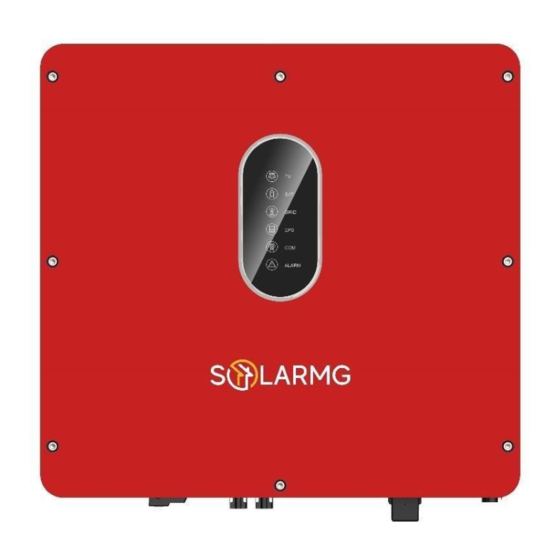
REV.2 S.MG-UM:SG 4-6HBS Product Introduction Product Introduction Product Introduction 2.2 Product Appearance 2.1 Overview 2.2.1 Hybrid Inverter Hybrid Inverter The hybrid inverters are high-quality inverter which can convert solar energy to AC energy and store energy into battery. The inverter can be used to optimize self consumption, store in the battery for future use or feed into public grid. -
Page 6: Model Definition
REV.2 S.MG-UM:SG 4-6HBS Product Introduction Product Introduction Battery Connect Terminals Battery Connect Terminals 2. DC Switch Communications Ports 3. PV Input Terminals (USB, PARAL, RS485, DRM, Communications Ports CT/METER, BMS, NTC/RMO/DRY) (USB, PARAL, RS485, DRM, GPRS/WiF Module Port CT/METER, BMS, NTC/RMO/DRY) GPRS/WiFi Module Port EPS Output Terminal EPS Output Terminal... -
Page 7: Installation
REV.2 S.MG-UM:SG 4-6HBS Installation Installation Installation 3.2 Selecting the Mounting Location 3.2.1 Installation Environment Requirements 3.1 Paking List After unpacking, please check the following packing list carefully for any damage or missing parts. If a. The storage inverter protection class is IP65 and can be mounted indoors or outdoors. any damage or missing parts occurs, contact the supplier for help. -
Page 8: Mounting
REV.2 S.MG-UM:SG 4-6HBS Installation Installation 3.3 Mounting 3.2.2 Mounting Requirements Before mounting the inverter, you have to prepare expansion bolts(specification: M12*80; with a wrong mode and the connection area must point downward. Quantity: 3). Step 1. Install the mounting bracket 1. -
Page 9: Electrical Connection
REV.2 S.MG-UM:SG 4-6HBS Electrical Connection Electrical Connection 4. Electrical Connection Single phase parallel connection mode-Scheme A This chapter shows the details connection of inverter. And PV connection is N/A for AC couple inverters. The following illustration only uses the hybrid inverters as an example. No.N In Inverter system connection diagram: PV Array... - Page 10 REV.2 S.MG-UM:SG 4-6HBS Electrical Connection Electrical Connection Single phase parallel connection mode-Scheme B Note: 1. BMS connection is only for lithium battery. 2. It is necessary to turn the matched resistance switch of No. 1 inverter and No. N inverter to “ON” in parallel connection mode.
-
Page 11: Grounding
REV.2 S.MG-UM:SG 4-6HBS Electrical Connection Electrical Connection 4.1 Grounding Note: 1. BMS connection is only for lithium battery. A protective earth (PE) terminal is equipped at the side of the inverter. Please be sure to connect this 2. It is necessary to additionally purchase suitable CT and meter according to the specific requirements PE terminal to the PE bar for reliable grounding. -
Page 12: Grid/Eps Connection
REV.2 S.MG-UM:SG 4-6HBS Electrical Connection Electrical Connection 4.2 Grid/EPS Connection 4.3 Battery Connection Grid/EPS connection please refer to below. This part in this manual only describe the battery connection on inverter side. If you need more detailed connection information about the battery side, please refer to the manual of the battery you using. Step 1: Assemble the AC connector. -
Page 13: Pv Connection
REV.2 S.MG-UM:SG 4-6HBS Electrical Connection Electrical Connection Meter/CT Connection PV connection please refer to below. You can monitor usage with a meter or a CT. 4.5.1 Meter Connection This section is applica le to non-parallel connection mode only. Click Inverter only supports the meter: CHNT-DDSU666 meter. The meter is optional. 4~6mm²... - Page 14 REV.2 S.MG-UM:SG 4-6HBS Electrical Connection Electrical Connection 4.5.2 CT Connection Communication Connection There are communication interfaces in the communication port on the bottom of the inverter Before connecting to Grid, please install a separate AC breaker ( 60A; not equipped) between CT and as show below:...
- Page 15 REV.2 S.MG-UM:SG 4-6HBS Electrical Connection Electrical Connection 4.6.1 4.6.2 DRMs Connection DRMs is a shortened form for “inverter demand response modes”. It is a compulsory requirements for inverters in Australia. Pin 12345678 RJ45 Terminal Configuration of DRMs Pin 12345678 Function RS485_ A RS485_B GND_S GND_S Description...
-
Page 16: Meter/Ct Connection
REV.2 S.MG-UM:SG 4-6HBS Electrical Connection Electrical Connection 4.6.3 Meter/CT Connection Connect meter. Refer to the following steps: RJ45 Terminal Configuration of Meter/CT Communication Pin 12345678 Insert RJ45 terminals into corresponding ports. Unscrew the waterproof cover Screw the waterproof cover back to inverter firmly and loosen the rubber nut on with 4 x M4 screws(1.2N.m). - Page 17 REV.2 S.MG-UM:SG 4-6HBS Electrical Connection Electrical Connection 4.6.3.2 CT Connection 4.6.4 RS485 Connection This section is applica le to non-parallel connection mode and parallel connection-scheme A only. 4-Pins Terminal Configuration of RS485 Communication CT cable connection overview Function RS485_A RS485_B Description Inverter Pin5(CT-)
-
Page 18: Communication Connection
REV.2 S.MG-UM:SG 4-6HBS Electrical Connection Electrical Connection 4.6.5 Parallel Communication Connection Refer to the following steps: 4-Pins Terminal Configuration of parallel Communication Function GND_S PARA_SYNC CAN_L CAN_H Description Parallel communication cable connection overview No. 1 Inverter No. 2 Inverter No. N Inverter PARAL RS485 PARAL RS485 PARAL RS485... - Page 19 REV.2 S.MG-UM:SG 4-6HBS Electrical Connection Electrical Connection 9-Pins Terminal Configuration of Auxiliary Communication Pin123456789 Function Description Function NO1 (Normal Open) NC1 (Normal Close) NC2 (Normal Close) NC2 (Normal Close) REMO OFF GND S (NTC BAT) NTC BAT+ Insert its 9-Pins terminal into the corresponding NTC/RMO/DRY port on the inverter. Refer to the following steps: Install the seal into the threaded sleeve, fasten the rubber nut and screw the waterproof cover back to inverter firmly with 4 x M4 screws;...
-
Page 20: System Operation
REV.2 S.MG-UM:SG 4-6HBS System Operation System Operation System Operation 5.1 Inverter Working Mode The inverter supports several different working modes. 5.1.1 Self Used Mode Go to the "Hybrid work mode" menu, and select the "Self used mode" working mode. Under Self Used mode, the priority of PV energy will be Load > Battery > Grid, that means the energy produced by PV gives priority to local loads, excess energy is used for charging the battery, and the remaining energy is fed into the grid. - Page 21 REV.2 S.MG-UM:SG 4-6HBS System Operattion System Operation a) Wealthy PV Energy c) No PV Input When PV energy is wealthy, the PV energy will be first consumed by loads, if there is The inverter will first discharge the battery energy for home load consuming when no PV excess PV power, then the excessive power will be fed into grid.
- Page 22 REV.2 S.MG-UM:SG 4-6HBS System Operattion System Operation 5.1.4 Back-up Charge Allow AC charging Go to the "Hybrid work mode" menu, and select the "Back-up Charge" working mode. In this situation, the battery can be charged both with PV and AC. Under this mode, the priority of PV energy will be Battery >...
- Page 23 REV.2 S.MG-UM:SG 4-6HBS System Operattion System Operation Allow AC charging 5.1.5 Back-up Load Go to the "Hybrid work mode" menu, and select the "Back-up Load" working mode. In this situation, the battery can be charged both with PV and AC. Under this mode, the priority of PV energy will be Load >...
- Page 24 REV.2 S.MG-UM:SG 4-6HBS System Operattion System Operation 5.1.6 Off Grid Mode b) Limited PV power When PV energy is limited, EPS loads are first powered by PV and then supplemented by When the power grid is cut off, the system automatically switches to Off Grid mode. battery.
-
Page 25: Startup/Shutdown The System
REV.2 S.MG-UM:SG 4-6HBS System Operattion Commissioning 6. Commissioning Startup/Shutdown the System 5.2.1 Startup the System It is necessary to make a complete commissioning of the inverter system. This will essentially protect the system from fire, electric shock or other damages or injuries. Check and confirm the installation is secure and strong enough and that the system grounding is OK. -
Page 26: User Interface
REV.2 S.MG-UM:SG 4-6HBS User Interface User Interface 7. User Interface ALARM Grid Details Code Details 7.1 LED PV normal PV normal This section describes the LED panel. LED indicator includes PV, BAT, No PV No PV GRID, EPS, COM, ALARM indicators. PV is N/A for AC couple. PV over voltage PV over voltage It includes the explanation of indicator states and summary of indicator... -
Page 27: App Setting Guide
REV.2 S.MG-UM:SG 4-6HBS User Interface User Interface ALARM Grid 7.2 App Setting Guide Details Code This section takes V6.4.5 as an example. WLAN/RS485/DB9/BLE/USB 7.2.1 Download App RS485/DB9/BLE/USB Scan the QR code on the inverter to download the APP. Inverter over temperature Inverter over temperature Download APP from the App Store or Google Play. - Page 28 REV.2 S.MG-UM:SG 4-6HBS User Interface User Interface 7.2.3 Local Setting Quick Setting Access Permission 1. Connect to the router. Step 1 Go to Quick Setting page. Before using the local setting, the APP should access some permissions. ( You can allow them when you install the APP or grant permissions in your own phone setting.
- Page 29 REV.2 S.MG-UM:SG 4-6HBS User Interface User Interface Chart 3. Set parameters of power limit XXXXXXXX Step 1 Click each item to enter the parameters Under this menu, you can you can check the relevant data curve of energy (including Daily, Monthly of power limit.
- Page 30 REV.2 S.MG-UM:SG 4-6HBS User Interface User Interface Different color curves represent energy data of different Local Setting Homepage the icon. This page shows the basic information of inverter. Click to display the warning message. Click the icon to show and hide the corresponding curve of the corresponding content.
- Page 31 REV.2 S.MG-UM:SG 4-6HBS User Interface User Interface You can burn software, switching device, do import and export functions in this page. Maintenance Go to Console page. And click Maintenance Then you need to enter password in a popup window (as shown below).
- Page 32 REV.2 S.MG-UM:SG 4-6HBS User Interface User Interface Console Communication Setting Go to Console > Communication Setting page. In this page, you can set or change the parameters of Access Management communication settings: Basic Setting, RS485 Setting and Ethernet Setting. Go to Console >...
- Page 33 REV.2 S.MG-UM:SG 4-6HBS User Interface User Interface Reactive Power Control Grid Parameters Go to Console > Grid Parameters page. In this page, you can Go to Console > Reactive Power Control page. In this page, you can set or change the Reactive Power set or change the parameters of Grid side, as shown in the figure.
-
Page 34: Maintenance
REV.2 S.MG-UM:SG 4-6HBS User Interface Maintenance 8. Maintenance Hybrid Setting Go to Console > Hybrid Setting page. In this page, you can set Hybrid Setting parameters. Before maintaining and commissioning inverter and its peripheral distribution CAUTION unit, switch off all the charged terminals of the inverter and wait at least 10 minutes after the inverter is powered off. -
Page 35: Inverter Troubleshooting
REV.2 S.MG-UM:SG 4-6HBS Maintenance Maintenance 8.2 Inverter Troubleshooting When the inverter has an exception, its basic common warning and exception handing methods are Code Alarm Information shown below. Inverter abnormal Code Alarm Information Suggestions and measures Boost abnormal 1. If the alarm occurs occasionally, possibly the power grid Grid over voltage voltage is abnormal for a short time, and no action is required. -
Page 36: Removing The Inverter
REV.2 S.MG-UM:SG 4-6HBS Maintenance Maintenance 8.3 Removing the Inverter Code Alarm Information Before removing DC input connector, double check DC input switch is turned WARNING to OFF to avoid inverter damage and personal injury. Battery over abnormal Perform the following procedures to remove the inverter: Battery under voltage Step 1. -
Page 37: Technical Specifications
REV.2 S.MG-UM:SG 4-6HBS Technical Specification Technical Specification 9. Technical Specifications Model 4K6HB-60 4K6HB-120 5KH B-60 5KHB-120 6KHB-60 6KHB-120 4K6AC 5KAC 6KAC Efficiency Max.efficiency (PV to AC) 97.3% Max.efficiency (BAT to AC) 94.0% 94.0% Input (PV) Max. PV power (W) 9000 Max. - Page 38 REV.2 S.MG-UM:SG 4-6HBS Technical Specification Technical Specification Model Model 4K6HB-60 4K6HB-120 5KH B-60 5KHB-120 6KHB-60 6KHB-120 4K6AC 5KAC 6KAC Output (Grid) Nominal AC output power (W) 4600 4600 5000 5000 6000 6000 4600 5000 6000 Max.AC output apparent power (VA)
- Page 39 REV.2 S.MG-UM:SG 4-6HBS Technical Specification Technical Specification Model 4K6HB-60 4K6HB-120 5KH B-60 5KHB-120 6KHB-60 6KHB-120 4K6AC 5KAC 6KAC Model 4K6HB-60 4K6HB-120 5KHB-60 5KHB-120 6KHB-60 6KHB-120 4K6AC 5KAC 6KAC Protection Protection Protection category Protection category Class I Class I Class I...
- Page 40 REV.2 S.MG-UM:SG 4-6HBS Technical Specification Technical Specification Model 4K6HB-60 4K6HB-120 5KHB-60 5KHB-120 6KHB-60 6KHB-120 4K6AC 5KAC 6KAC Relative humidity (%) 0~100 0~100 Cooling concept Natural Natural Mounting Wall bracket Wall bracket Dimensions (W*H*D) (515*487*175)mm (515*487*175)mm PV connection way MC4/H4 Battery connection way...
Need help?
Do you have a question about the 4K6HB-60 and is the answer not in the manual?
Questions and answers