Table of Contents
Advertisement
Quick Links
Installation and
Service Instructions
for use by heating contractor
Vitorond 100, VR1
Models 40 to 63, 161 to 245
Oil-Fired Boiler
Heating input 161 to 245 MBH
47 to 72 kW
VITOROND
H
5583 572 - 07
01/2024
100
r
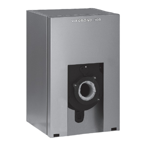
Product may not be exactly as shown
IMPORTANT
Read and save these instructions
for future reference.
Please file in Service Binder
Advertisement
Table of Contents

Related Manuals for Viessmann VITOROND 100 VR1 40


Summary of Contents for Viessmann VITOROND 100 VR1 40
- Page 1 Installation and Service Instructions for use by heating contractor Vitorond 100, VR1 Models 40 to 63, 161 to 245 Oil-Fired Boiler Heating input 161 to 245 MBH 47 to 72 kW VITOROND Product may not be exactly as shown IMPORTANT Read and save these instructions for future reference.
-
Page 2: Important Safety, Installation, Regulatory And Warranty Requirements
Installers must follow local regulations with respect to installation of carbon monoxide detectors. Follow the Viessmann maintenance schedule of the Warranty boiler in the “Service Instructions” manual. Information contained in this and related product documentation must be read and followed. - Page 3 Safety Vitorond 100, VR1 40 to 63, 161 to 245 Installation and Service Important Safety, Installation, Regulatory and Warranty Requirements (continued) H Fiberglass wool and ceramic fiber materials Suppliers of fiberglass wool products recommend the WARNING following precautions be taken when handling these materials: Inhaling of fiberglass wool and/or ceramic fiber Precautionary measures...
- Page 4 Safety Vitorond 100, VR1 40 to 63, 161 to 245 Installation and Service Important Safety, Installation, Regulatory and Warranty Requirements (continued) For installations on the Commonwealth of Massachusetts, the following modifications to NFPA-54 chapter 10 apply: Excerpt from 248 CMR 5-08: 2(a) For all side-wall horizontally vented gas fueled equipment installed in every dwelling, building or structure used in whole or in part for residential purposes, including those owned or operated by the Commonwealth...
- Page 5 Please - Operating Instructions and User’s Information Manual inquire. - Instructions of other Viessmann products utilized with All electrical wiring is to be done in accordance with the this installation latest edition of CSA C22.1 Part 1 and/or local codes. In - Hydrostat 3250-Plus instructions the U.S.
-
Page 6: Table Of Contents
Table of Contents Vitorond 100, VR1-40 to -63 Installation and Service Page Safety Important Safety, Installation, Regulatory and Warranty Requirements..........2 General Information About these Instructions..........7 Product Information.............8 Mechanical Room............9 Combustion Air Supply..........9 Set-up Product Delivery............11 Unpacking Instructions..........11 Minimum Clearances to Combustibles......12 Recommended Minimum Clearances for Service...12 Boiler Set-up and Location ........13 Insulation Installation..........13... -
Page 7: About These Instructions
General Information Vitorond 100, VR1 40 to 63, 161 to 245 Installation and Service About these Instructions Take note of all symbols and notations intended to draw attention to potential hazards or important product information. These include “WARNING”, “CAUTION”, and “IMPORTANT”. See below. uWarnings draw your attention to the presence of WARNING potential hazards or important product information. -
Page 8: Product Information
A bypass can be installed on any system as a preventative measure. Viessmann strongly recommends installing a bypass pipe on all cast iron boilers. Hydrostat thermal targeting... -
Page 9: Mechanical Room
18 in. room. (457 mm) above the floor to avoid contact with flammable vapors and fumes). Viessmann strongly recommends installing the boiler on a concrete foundation. Combustion Air Supply General WARNING... - Page 10 General Information Vitorond 100, VR1 40 to 63, 161 to 245 Installation and Service Combustion Air Supply (continued) Codes Installation Provisions for combustion and ventilation air must be Install a combustion air opening. Round duct diameters made in accordance with applicable local codes. are as follows: In the absence of local codes, use: Boiler Model No.
-
Page 11: Product Delivery
CAUTION To avoid injury and to facilitate boiler maneuvering, Do not lift or position boiler alone. it is strongly recommended that Viessmann carrying Do not lift by or push against panels. handles (Part No. 7189 602) be used. The carrying Do not bump boiler panels against floor. -
Page 12: Minimum Clearances To Combustibles
Set-up Vitorond 100, VR1 40 to 63, 161 to 245 Installation and Service Minimum Clearances to Combustibles For typical installations, Viessmann recommends installing the boiler with clearances under Recommended Minimum Clearances for Service. The following are clearances to combustibles: Standard installation... -
Page 13: Boiler Set-Up And Location
Set-up Vitorond 100, VR1 40 to 63, 161 to 245 Installation and Service Boiler Set-up and Location IMPORTANT For important information concerning boiler placement and set-up, refer to the section entitled “Mechanical Room” on page 9. The boiler should be located as close to the chimney as possible. - Page 14 Set-up Vitorond 100, VR1 40 to 63, 161 to 245 Installation and Service Insulation Installation (continued) If installing Vitotronic control: Run the fA plug-in connector cable of the Vitotronic control down behind the front panel of the boiler and out through the bottom. Install support brackets A.
- Page 15 Set-up Vitorond 100, VR1 40 to 63, 161 to 245 Installation and Service Insulation Installation (continued) 10. Install right side panel on support brackets. Ensure top of side panel fits over top of rear panel. 11. Line up bottom tab of side panel with notch in casting leg.
-
Page 16: Combustion Chamber Insert
Set-up/Connections Vitorond 100, VR1 40 to 63, 161 to 245 Installation and Service Combustion Chamber Insert For optimum, environmentally sound operation, Vitorond boilers are equipped with a high-grade, corrosion resistant, stainless steel combustion chamber insert. Ensure the bolts of the combustion chamber door are tightened before installing the burner. - Page 17 Connections Vitorond 100, VR1 40 to 63, 161 to 245 Installation and Service Venting Connection (continued) General The chimney shall be capable of exhausting the The heating contractor shall ensure all of the following products of combustion and of producing a draft requirements are met: not less than that recommended by the manufacturer The vent system shall ensure that no hazard is created...
- Page 18 6. Seal all flue pipe joints. 7. Viessmann recommends that any non-insulated vent pipe is insulated to reduce cooling of flue gas and velocity noises. Legend...
-
Page 19: Water Side Connections (With Hydrostat 3250-Plus Control)
Connections Vitorond 100, VR1 40 to 63, 161 to 245 Installation and Service Water Side Connections (with Hydrostat 3250-Plus Control) IMPORTANT This boiler is designed for closed loop, forced circulation heating systems only. 1. Flush heating system thoroughly (particularly with existing systems which have been in operation for years). -
Page 20: Safety Connections (With Hydrostat 3250-Plus Control)
Connections Vitorond 100, VR1 40 to 63, 161 to 245 Installation and Service Safety Connections (with Hydrostat 3250-Plus Control) Pressure relief valve 1. Install pressure relief valve. Pipe pressure relief valve as illustrated and connect to boiler water supply connection. Refer to instructions supplied with the pressure relief valve. - Page 21 Connections Vitorond 100, VR1 40 to 63, 161 to 245 Installation and Service Safety Connections (with Hydrostat 3250-Plus Control) (continued) 1. To avoid problems with removing the top panel, we recommend moving the top panel screw approximately 3” to the left or right. To do so, pre-drill the panel with an 1/8”...
-
Page 22: Water Side Connections (With Vitotronic Control)
Connections Vitorond 100, VR1 40 to 63, 161 to 245 Installation and Service Water Side Connections (with Vitotronic Control) IMPORTANT This boiler is designed for closed loop, forced circulation heating systems only. 1. Flush heating system thoroughly (particularly with existing systems which have been in operation for years). -
Page 23: Safety Connections (With Vitotronic Control)
Connections Vitorond 100, VR1 40 to 63, 161 to 245 Installation and Service Safety Connections (with Vitotronic Control) Pressure relief valve 1. Install pressure relief valve. Pipe pressure relief valve as illustrated and connect to boiler water supply connection. Refer to instructions supplied with the pressure relief valve. - Page 24 Connections Vitorond 100, VR1 40 to 63, 161 to 245 Installation and Service Safety Connections (with Vitotronic Control) (continued) 1. To avoid problems with removing the top panel, we recommend moving the top panel screw approximately 3” to the left or right. To do so, pre-drill the panel with an ”...
-
Page 25: Pressure Testing
Connections Vitorond 100, VR1 40 to 63, 161 to 245 Installation and Service Pressure Testing Perform pressure test on boiler The boiler must be leak tested before being placed in operation. Before boiler is connected to piping or electrical power supply, it must be hydrostatically pressure tested with a maximum of 1½... -
Page 26: Burner Installation
Observe all instructions supplied with the burner. Burner Information Fuel This boiler is for use with the #2 fuel oil burner supplied by Viessmann only. Use only the fuel stated on the rating plate of the burner. WARNING DO NOT USE GASOLINE, CRANKCASE DRAININGS OR ANY OIL CONTAINING GASOLINE. -
Page 27: Burner Mounting
Burner Set-up Vitorond 100, VR1 40 to 63, 161 to 245 Installation and Service Burner Mounting Refer to manufacturers instructions supplied with the burner. 1. Remove burner from carton. The mounting flange has been installed at the factory. 2. Mount four M8 spacer bolts A in threaded holes of combustion chamber door. -
Page 28: Oil Piping Connection
Burner Set-up Vitorond 100, VR1 40 to 63, 161 to 245 Installation and Service Oil Piping Connection General Oil piping requirements Location and installation of oil tanks, oil piping and burners must follow: - Local codes and regulations. - Information provided with burner and fuel pump. - In Canada, CSA B139, Installation of Oil-Burning Equipment. -
Page 29: Electrical Connections (With Hydrostat 3250-Plus Control)
Burner Set-up Vitorond 100, VR1 40 to 63, 161 to 245 Installation and Service Electrical Connections (with Hydrostat 3250-Plus Control) Installations must follow these codes and requirements: WARNING - National Electrical Code, ANSI/NFPA 70, latest edition and any additional national, state or local codes. Electric shock hazard. - Page 30 Burner Set-up Vitorond 100, VR1 40 to 63, 161 to 245 Installation and Service Electrical Connections (with Hydrostat 3250-Plus Control) (continued) WARNING Electric shock hazard. Can cause severe personal injury or loss of life if power source, including service switch on boiler, is not disconnected before installing or servicing.
- Page 31 Burner Set-up Vitorond 100, VR1 40 to 63, 161 to 245 Installation and Service Electrical Connections (with Hydrostat 3250-Plus Control) (continued) Installations must follow these codes and requirements: WARNING National Electrical Code, ANSI/NFPA 70, latest edition and any additional national, state or local codes. Ensure that the burner cycles ON and OFF on proper In Canada, CSA C22.1 Canadian Electrical Code call for heat before leaving the job site.
- Page 32 Burner Set-up Vitorond 100, VR1 40 to 63, 161 to 245 Installation and Service Electrical Connections (with Hydrostat 3250-Plus Control) (continued) Riello burner Legend IMPORTANT A Power supply, provide disconnect means and overload protection as required. B Control case must be connected to earth ground. Red wire not used in this application.
-
Page 33: Electrical Connections (With Vitotronic Control)
Burner Set-up Vitorond 100, VR1 40 to 63, 161 to 245 Installation and Service Electrical Connections (with Vitotronic Control) Installations must follow these codes WARNING and requirements: - National Electrical Code, ANSI/NFPA 70, latest edition Electric shock hazard. Can cause severe personal injury and any additional national, state or local codes. - Page 34 Burner Set-up Vitorond 100, VR1 40 to 63, 161 to 245 Installation and Service Electrical Connections (with Vitotronic Control) (continued) Refer to Installation Instructions Boiler Control (for all connections to control base) IMPORTANT The power supply cable is shipped with the boiler control. 1.
- Page 35 Burner Set-up Vitorond 100, VR1 40 to 63, 161 to 245 Installation and Service Electrical Connections (with Vitotronic Control) (continued) Removing and installing top panel 1. To avoid problems with removing the top panel, we recommend moving the top panel screw approximately 3”...
- Page 36 Burner Set-up Vitorond 100, VR1 40 to 63, 161 to 245 Installation and Service Electrical Connections (with Vitotronic Control) (continued) WARNING Electric shock hazard. Can cause severe personal injury or loss of life if power source, including service switch on boiler, is not disconnected before installing or servicing. Installations must follow these codes and requirements: - National Electrical Code, ANSI/NFPA 70, latest edition and any additional national, state or local codes.
- Page 37 Burner Set-up Vitorond 100, VR1 40 to 63, 161 to 245 Installation and Service Electrical Connections (with Vitotronic Control) (continued) WARNING WARNING Electric shock hazard. Can cause severe personal injury Ensure that the burner cycles ON and OFF on proper call or loss of life if power source, including service switch for heat before leaving the job site.
- Page 38 Burner Set-up Vitorond 100, VR1 40 to 63, 161 to 245 Installation and Service Electrical Connections (with Vitotronic Control) (continued) Riello burner Legend BL Blue OG Orange BK Black W White Green/Ground Yellow Violet BR Brown GY Gray Carlin burner...
-
Page 39: Initial Start-Up
Start-up Vitorond 100, VR1 40 to 63, 161 to 245 Installation and Service Initial Start-up 1. Ensure fresh air intake of boiler room is open and that chimney and all flue pipes are connected, sealed and WARNING unobstructed inside. Verify completeness of all discussion points on the 2. -
Page 40: Burner Calibration
Start-up Vitorond 100, VR1 40 to 63, 161 to 245 Installation and Service Burner Calibration WARNING Refer to the Instructions supplied with the burner. DO NOT USE GASOLINE, CRANKCASE DRAININGS OR ANY OIL CONTAINING GASOLINE. Combustion analysis This oil burner requires combustion measurements performed at the final installation site, using calibrated WARNING combustion equipment, to verify factory settings, or to... - Page 41 Start-up Vitorond 100, VR1 40 to 63, 161 to 245 Installation and Service Burner Calibration (continued) Boiler Model No. VR1 40, 161 VR1 50, 196 VR1 63, 245 Burner model Beckett NX-VI 704 AFG-VI 801*1 AFG-VI 801*1 No. 2 fuel oil No.
- Page 42 Start-up Vitorond 100, VR1 40 to 63, 161 to 245 Installation and Service Burner Calibration (continued) Boiler Model No. VR1 40, 161 VR1 50, 196 VR1 63, 245 Burner model Carlin EZ-1-HP EZ-66 EZ-66 No. 2 fuel oil No. 2 fuel oil No.
-
Page 43: Barometric Draft Regulator
They further do not display all system varieties, safety devices, or concepts possible. Specific system layouts may be further discussed with the local Viessmann sales representative office. Clearances A minimum of 2” circumferential clearance from non- insulated hot water pipes to combustible construction must be maintained. -
Page 44: Installation Examples - Hydrostat 3250-Plus
Connections Vitorond 100, VR1 40 to 63, 161 to 245 Installation and Service Installation Examples - Hydrostat 3250-Plus Boiler in a heating/cooling application Cooling season starts: close valve v1 and open valve v2 Heating season starts: close valve v2 and open valve v1 Legend IMPORTANT A Heating/Cooling unit... -
Page 45: Installation Examples - Vitotronic
Connections Vitorond 100, VR1 40 to 63, 161 to 245 Installation and Service Installation Examples - Vitotronic Without mixing valve e.g. with Vitotronic 100, Model KW10B Legend A Heating circuit B Spring-loaded flow check valve C Circulation pump D Automatic air vent, (field supplied), pressure relief valve, and temperature pressure guage E Expansion tank F Low water cut-off (if required) - Page 46 Connections Vitorond 100, VR1 40 to 63, 161 to 245 Installation and Service Installation Examples - Vitotronic (continued) With one low-temperature circuit with 4-way mixing valve, and with domestic hot water production e.g. with Vitotronic 200, Model KW2 combined with one mixing valve actuator accessory kit Legend A Heating circuit...
- Page 47 Connections Vitorond 100, VR1 40 to 63, 161 to 245 Installation and Service Installation Examples - Vitotronic (continued) With one low-temperature circuit with 4-way mixing valve, one high temperature circuit, and with domestic hot water production e.g. with Vitotronic 200, Model KW2 combined with one mixing valve actuator accessory kit Legend A Heating circuit...
-
Page 48: Necessary Tools
Service Vitorond 100, VR1 40 to 63, 161 to 245 Installation and Service Necessary Tools IMPORTANT WARNING Use only calibrated equipment. Ensure that warning concerning fiberglass wool and ceramic fiber materials on page 3 has been read and understood before handling insulation. Testing/analysis equipment H Calibrated flue gas analyzer WARNING... -
Page 49: Clean Heat Exchanger And Flue Pipe
Service Vitorond 100, VR1 40 to 63, 161 to 245 Installation and Service Service Procedure (continued) Clean heat exchanger and flue pipe 1. Clean heat exchanger with field supplied cleaning brush and use vacuum cleaner to remove all sediment. 2. Remove all sediment from flue pipe and flue gas collector using vacuum cleaner. -
Page 50: Check Heating System And Domestic Hot Water Connections
Service Vitorond 100, VR1 40 to 63, 161 to 245 Installation and Service Service Procedure (continued) Check heating system and domestic hot water connections Ensure all connections are pressure tight. Ensure proper operation of all safety devices Check pressure gage, air vent and pressure relief valve. Ensure pressure relief valve does not leak. -
Page 51: Calibrate The Burner
Service Vitorond 100, VR1 40 to 63, 161 to 245 Installation and Service Service Procedure (continued) Calibrate the burner WARNING Refer to the Instructions supplied with the Beckett or Riello burner. DO NOT USE GASOLINE, CRANKCASE DRAININGS OR ANY OIL CONTAINING GASOLINE. Note: For burner technical information refer to table on page 41 or page 42. -
Page 52: Parts List
VR1 63, 245 7344558 Ordering Replacement Parts: Please provide boiler Model and Serial Number from rating plate when ordering replacement parts. Order replacement components from your Viessmann distributor. Parts 202 Top panel, front 203 Side panel, left 204 Insulation blanket... - Page 53 Additional Information Vitorond 100, VR1 40 to 63, 161 to 245 Installation and Service Parts List (continued) Parts 001 5-Point sensor well 002 Combustion chamber door refractory 003 Combustion chamber door 004 Hinge bracket 005 Glass-fiber gasket 006 Glass-fiber gasket, 3x116 mm *1 008 Observation port cover 010 Glass-fiber gasket, 013 Turbulator insert *2...
- Page 54 Additional Information Vitorond 100, VR1 40 to 63, 161 to 245 Installation and Service Parts List (continued) Parts 0701 Hydrostat control, Model 3250-Plus 0702 Electro-well, extended ¾” NPT 0703 Hex bushing, 1½” x ¾” 0704 Temperature and pressure gage 0705 Reduction tee, 2” x 2” x ½” 0706 Nipple, 2”...
-
Page 55: Maintenance Record
Additional Information Vitorond 100, VR1 40 to 63, 161 to 245 Installation and Service Maintenance Record WARNING Neglecting to perform necessary maintenance can cause unsafe operation. Before each heating season begins, have the following service and maintenance done by a licensed, professional heating contractor: 1. - Page 56 Vitorond 100, VR1 40 to 63, 161 to 245 Installation and Service...
Need help?
Do you have a question about the VITOROND 100 VR1 40 and is the answer not in the manual?
Questions and answers