
Subscribe to Our Youtube Channel
Related Manuals for Wenglor IR 00 Series


Summary of Contents for Wenglor IR 00 Series
- Page 1 IRxx00x Inductive Ring Sensor Operating Instructions Translation of the original operating instructions Subject to change without notice Available as PDF file only Version 1.0.0 As of: 7/04/2023 www.wenglor.com...
-
Page 2: Table Of Contents
Table of Content General ................................4 Information Concerning these Instructions ..................4 Explanations of Symbols ........................4 Limitation of Liability ..........................5 Copyrights ............................5 For Your Safety ............................6 Use for Intended Purpose ........................6 Use for Other than the Intended Purpose ....................6 Personnel Qualifications ........................6 Modification of Products ........................6 General Safety Precautions .........................7 Approvals and Protection Class ......................7... - Page 3 Setup via IO-Link .............................19 Maintenance Instructions ........................20 Proper Disposal ............................20 10. Appendix ..............................20 10.1 Revision History ..........................20 10.2 Declarations of Conformity .........................20 Inductive Sensors...
-
Page 4: General
• Local accident prevention regulations and national work safety regulations must be complied with as well. • The product is subject to further technical development, and thus the information contained in these oper- ating instructions may also be subject to change. The current version can be found at www.wenglor.com in the product’s separate download area. -
Page 5: Limitation Of Liability
• wenglor assumes no liability for printing errors or other inaccuracies contained in these operating instruc- tions unless wenglor was verifiably aware of such errors at the point in time at which the operating instruc- tions were prepared. -
Page 6: For Your Safety
• The product is not suitable for use in potentially explosive atmospheres. • The product may be used only with accessories supplied or approved by wenglor, or in combination with approved products. A list of approved accessories and combination products can be found at www.wenglor.com... -
Page 7: General Safety Precautions
• In the event of possible changes, the current version of the operating instructions can be found at www.wenglor.com in the product’s separate download area. • Read the operating instructions carefully before using the product. -
Page 8: Technical Data
Technical Data 3.1 General Data IR2D001 IR3D001 Inductive Data Inside Diameter 10.2 mm 15.1 mm Functional Principle Dynamic Smallest Recognizable Object (∅) 2 mm * 2.5 mm* Correction Factors for V2A Stainless 1/1/1 Steel/CuZn/Al Electrical Data Supply Voltage 10…30 V DC Current Consumption <... -
Page 9: Housing Dimensions
3.2 Housing Dimensions IR2x00x IR3x00x Inductive Sensors... -
Page 10: Connection Diagram
3.3 Connection Diagram Applies to sensors designated IRxx001 Legend Encoder A/A (TTL) Platinum measuring resistor Encoder B/B (TTL) Supply Voltage + not connected Encoder A Supply Voltage 0 V Test Input Encoder B Supply Voltage (AC Voltage) Test Input inverted Switching Output (NO) Digital output MIN... -
Page 11: Complementary Products
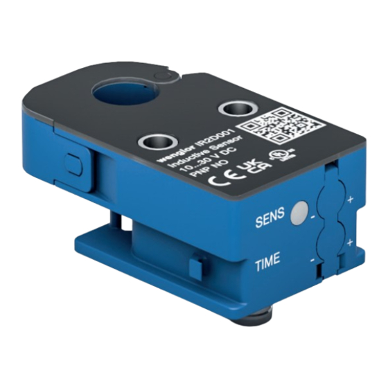
3.4 Complementary Products wenglor can provide you with suitable connection equipment for your product. Mounting technology: soft binder ZR0E001 Connection line: S60, S61, ZCFL 3.5 Control Panel 17 = Sensitivity adjuster 0b = Pulse length adjuster 1c = Status display/setup aid... -
Page 12: Transport And Storage
Transport and Storage 4.1 Transport Upon receipt of shipment, the goods must be inspected for damage in transit. In the case of damage, con- ditionally accept the package and notify the manufacturer of the damage. Then return the device, making reference to damage in transit. -
Page 13: Installation Using The Soft Binder
5.1.1 Installation Using the Soft Binder • Insert the soft binder on the hinge side (to prevent • Place the soft binder around the feed tube it from being lost) and thread it through the feed- through • Open the device’s hanger •... -
Page 14: Other Installation Options
5.1.2 Other Installation Options As a further installation option, the sensor has two holes that can be used to install the sensor using mounting technology. Please note that suitable mounting technology must be provided by the customer. The maximum tightening torque when using an M4 mounting screw is 2.9 Nm. In addition, the minimum installation distance to metal (cf. -
Page 15: Smallest Recognizable Object
NOTE! • Shut down the machine. • If the error cannot be eliminated, please contact wenglor’s support department. • Do not operate in case of indeterminate malfunctioning. • The machine must be shut down if the error cannot be definitively explained or properly eliminated. -
Page 16: Functions Overview
Functions Overview This section explains the sensor’s functions and LED symbols in more detail. 6.1 Function Description This function description refers to a setting on the potentiometer of the sensor. 6.1.1 Starting Up the Product As Supplied • Device is ready for use and can be put into operation The sensitivity is at the maximum setting in order to be able to detect the smallest possible objects. - Page 17 Set the pulse length: The pulse length adjuster can be used to set the time until the signal drops at the output between 5 ms and 200 ms. The following applies to sensors based on the dynamic principle: Target Output = Time target = Time delay = Time pause 5 ms...
-
Page 18: Led Symbols
6.2 LED Symbols Setup display Switching status indicator/supply Cause voltage indicator No object present yet Blue Green* Object was not reliably detected Blue Green** Object was reliably detected Blue Green Green Object was not detected Blue ̶ Hanger not closed The device has an error. - Page 19 Setup via IO-Link Process and parameter data can be found in the interface protocol at: www.wenglor.com Product World Enter the desired product number as a search term Under “Downloads” on the product page. Process Data: • Counter •...
- Page 20 10. Appendix 10.1 Revision History Version Date Description/Changes 1.0.0 7/04/2023 Initial version of the operating instructions 10.2 Declarations of Conformity Declarations of conformity can be found on our website at www.wenglor.com in the product’s separate down- load area. Maintenance Instructions...
Need help?
Do you have a question about the IR 00 Series and is the answer not in the manual?
Questions and answers