
Subscribe to Our Youtube Channel
Related Manuals for PhaseOne iX Controller MK 6


Summary of Contents for PhaseOne iX Controller MK 6
- Page 1 Controller MK 6 Installation and Operation Guide Version: 1.1 Date: November 13, 2023...
- Page 2 You can contact Phase One Technical Support directly by creating a support case at https://support.phaseone.com/ Visit https://geospatial.phaseone.com/ for additional information. Copyright © 2023 Phase One. All Rights Reserved. Doc No. 80115000 Rev 1.1 iX Controller MK 6 Installation and Operation Guide 13/11/2023 Page 2 of 28...
-
Page 3: Table Of Contents
Controller MK 6 – Operator Monitor Cable (P/N 75098530) ............15 Keyboard and Mouse ................................15 Reassembling the USB Cable Bracket ..........................16 iX Controller MK 6 - Mount COM Cable (P/N 73260000 / 73285000 / 73293000) ......16 External IMU ....................................17 4.10 PPS Output ..................................... - Page 4 Controller MK 6 Weight ..............................26 Power Specifications ................................26 A.3.1 Power Requirements ............................... 26 A.3.2 Power Consumption ..............................26 Appendix B Connecting the iX Controller MK 6 – Operator Monitor Cable to the Monitor ........27 Page 4 of 28...
-
Page 5: Introduction
Section 9 - Troubleshooting • Section 10 - Maintenance • Appendix A - Technical Data • Appendix B - Connecting the iX Controller MK 6 – Operator Monitor Cable to the Monitor Applicable Documents Item Manual Applanix AP+ APX-15 User Guide... -
Page 6: Controller Mk 6 Hardware Overview
2 iX Controller MK 6 Hardware Overview General The iX Controller MK 6 is a new generation of aerial controller. This robust command center onboard the aircraft is designed for smooth performance of geospatial project missions. A preconfigured precision GNSS AP+ card is integrated inside the controller. -
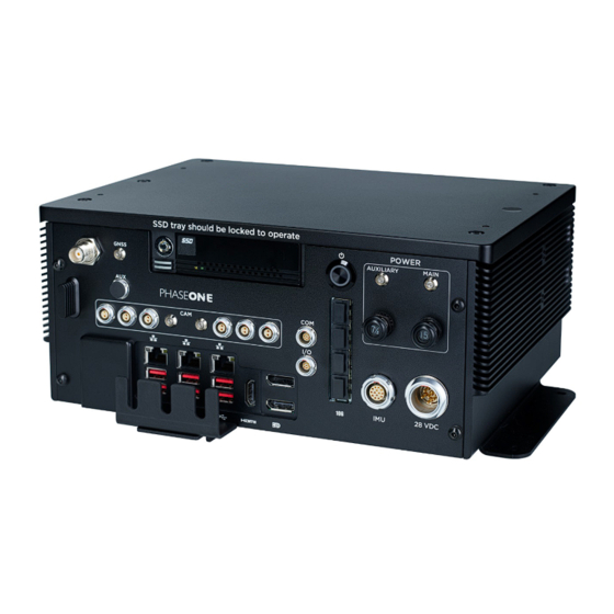
Page 7: Front Panel Description
The Auxiliary power circuit breaker controls power to the six power ports. The output voltage from all six power ports is the same as the incoming voltage from the iX Controller MK 6 power source. Each set of power ports can be software-controlled using iX Capture and iX Flight Pro. -
Page 8: Configuration Options
Controller MK 6 Installation and Operation Guide 2. iX Controller MK 6 Hardware Overview 2.4 Configuration Options The iX Controller MK 6 with its internal GNSS supports connection to the following IMUs for a range of orientation accuracies: •... -
Page 9: Unboxing The Ix Controller Mk 6
Verify that all parts were supplied according to the specific packing list for your iX Controller MK 6. Product Identification To enable support for your iX Controller MK 6, you must identify and record the serial number located on the left panel. -
Page 10: Connecting System Cables To The Ix Controller Mk 6
4. Connecting System Cables to the iX Controller MK 6 4 Connecting System Cables to the iX Controller MK 6 This section describes how to connect the power and various system components to the iX Controller MK 6. Warning The power ports support only equipment approved Phase One, such as cameras, external GNSS and monitors. -
Page 11: Grounding Cable
2. Connect the other end to the aircraft frame. 4.3 Disassembling the USB Cable Bracket The USB cable bracket secures the USB cable hoods to the iX Controller MK 6. Before connecting or removing any USB cables, you must disassemble the cable bracket front plate, and in some cases reposition the cable bracket bottom plate, as described in this section. -
Page 12: Connecting Ix Controller Mk 6 - Ix Camera Cables
4.4.1 iX Controller MK 6 - Camera Power Cable (P/N 70364000) The iX Controller MK 6 - Camera power cable provides power to the iX camera. To connect iX Controller MK 6 - Camera power cables: 1. Connect one end of the iX Controller MK 6 - Camera power cable to an iX Controller MK 6 power port. -
Page 13: Controller Mk 6 - Camera I/O Cables (P/N 75010000)
75007000) ordered separately. 4.4.3 iX Controller MK 6 - Camera Images/Data Cables You can transfer the images and associated data between iX Controller MK 6 and the iX cameras for storage on the SSD using either of the following methods: •... -
Page 14: Connecting Monitor Cables
Connecting USB Cables (P/N 73234000) The iX Controller MK 6 - Camera USB cable (supplied with each camera) transfers control data from the iX Controller MK 6 and the camera, and images from the camera for storage in the iX Controller MK 6. -
Page 15: Controller Mk 6 - Pilot Monitor Cable (P/N 75098490)
DP port and one of the USB 3 ports. 4.6 Keyboard and Mouse A Bluetooth keyboard with touchpad is provided with the iX Controller MK 6. To connect the keyboard to the iX Controller MK 6: 1. On the iX Controller MK 6, connect the keyboard’s Bluetooth dongle to a USB... -
Page 16: Reassembling The Usb Cable Bracket
1. Gently place the iX Controller MK 6 on its upper plate. 2. Remove both screws securing the cable bracket bottom plate to the iX Controller MK 6. 3. Mount the cable bracket bottom plate to the iX Controller MK 6 using the holes near the bottom plate edge. -
Page 17: External Imu
1. Connect one end of the IMU cable to the IMU. 2. Connect the other end of the IMU cable to the iX Controller MK 6 IMU port. 4.10 PPS Output The internal GNSS provides a pulse-per-second (PPS) time synchronization output mark. -
Page 18: Antenna Cable (P/N 76014600)
Controller MK 6 Installation and Operation Guide 4. Connecting System Cables to the iX Controller MK 6 4.11 Antenna Cable (P/N 76014600) To connect the antenna to the iX Controller MK 6: 1. Connect the antenna cable (supplied with antenna) to the Antenna port. -
Page 19: Powering Up The Ix Controller Mk 6
3. When the Windows login window appears, log in using the following credentials: User name: user No password required. Note To remotely login to the iX Controller MK 6, see Connecting to the iX Controller Using Remote Desktop Connection available for download at https://www.phaseone.com/download-categories/geo- guides-documentation/ Page 19 of 28... -
Page 20: Controller Mk 6 Storage
Operations Guide. 6.2 Locking the Carrier Note The carrier must be locked with the SSD carrier key for the iX Controller MK 6 to recognize the drives. To lock the carrier in the SSD drive bay frame: Note The SSD carrier key is stored on the left side of the iX Controller MK 6 front panel. -
Page 21: Removing The Ssd Drive Carrier
4. Insert the SSD carrier key into the SSD carrier keylock and turn it 90° clockwise. 5. Power up the iX Controller MK 6 as described in Section 5 - Powering up the iX Controller MK 6. 6. Verify that the green SSD drive LED turns on. -
Page 22: Operating The Ix Controller Mk 6
7.4.1 Controlling iX Controller MK 6 Power Ports through iX Flight Pro Through iX Flight Pro, you can control both sets of iX Controller MK 6 power ports. To control power to the power ports through iX Flight Pro: 1. Navigate to Camera Settings. -
Page 23: Shutting Down The Ix Controller Mk 6
On iX Controller MK 6, press the On/Off pushbutton. On the operator monitor, shut down Windows. 2. After the On/Off pushbutton white LED turns off: on the iX Controller MK 6, pull the MAIN circuit breaker out. Page 23 of 28... -
Page 24: Troubleshooting
Issue Solution Cannot close iX Capture with mouse. On the keyboard, press Alt+F4. iX Controller MK 6 MAIN Power LED is on, Press the On/Off pushbutton and verify that pushbutton but Windows 10 does not appear. white LED is on. -
Page 25: Maintenance
10 Maintenance 10.1 Replacing SSD Drives The iX Controller MK 6 is factory provided with 2 x 2TB or 2 x 4TB SSD drives installed in a removable carrier. You can replace the SSDs as required. To achieve optimal performance, both SSDs should have a high writing speed (>500 MB/S). -
Page 26: Appendix A Technical Data
Controller MK 6 Installation and Operation Guide Appendix A. Technical Data Appendix A Technical Data Physical Dimensions • Width: 310 mm / 12.2 in • Height: 130 mm / 5.1 in • Depth: 230 mm / 9.1 in iX Controller MK 6 Weight •... -
Page 27: Appendix B Connecting The Ix Controller Mk 6 - Operator Monitor Cable To The Monitor
If the operator monitor cable is not connected to the operator monitor, perform the procedure in this appendix. The iX Controller MK 6 – Operator Monitor Cable is connected to the operator monitor through the cable bracket on the rear of the monitor. - Page 28 Controller MK 6 Installation and Operation Guide Appendix B. Connecting the iX Controller MK 6 – Operator Monitor Cable to the Monitor 4. Insert the iX Controller - Operator Monitor cable into the cable bracket and connect the following connectors: ...
Need help?
Do you have a question about the iX Controller MK 6 and is the answer not in the manual?
Questions and answers