
Subscribe to Our Youtube Channel
Related Manuals for PhaseOne iX Controller MK 5


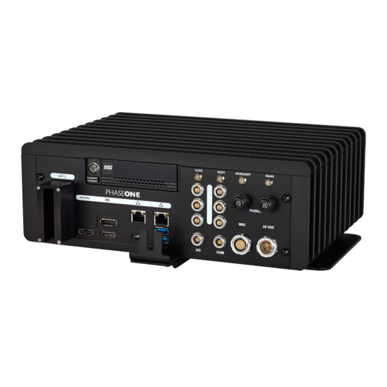
Summary of Contents for PhaseOne iX Controller MK 5
- Page 1 Controller MK 5 Installation and Operation Guide Version: 5.0.4 Date: April 18, 2023...
- Page 2 You can contact Phase One Technical Support directly by creating a support case at https://support.phaseone.com/ Visit https://geospatial.phaseone.com/ for additional information. Copyright © 2023 Phase One. All Rights Reserved. Doc No. 80077000 Rev 5.0.4 iX Controller MK 5 Installation and Operation Guide 18/04/2023 Page 2 of 29...
-
Page 3: Table Of Contents
Controller MK 5 Power Cable (P/N 70348000) ..................... 11 Grounding Cable ..................................12 iX Controller/iX Camera Power Cable (P/N 70364000) ..................12 iX Controller MK 5 to Camera I/O Cables (P/N 70378000) ................13 iX Controller MK 5 to Camera USB 3.0 Cables ......................14 Monitors ......................................15 Keyboard and Mouse ................................ - Page 4 Controller MK 5 Installation and Operation Guide Table of Contents Troubleshooting ......................................25 Maintenance ........................................ 26 10.1 Replacing SSD Drives................................26 Appendix A Technical Data ................................... 28 iX Controller MK 5 Weight ..............................28 Power Specifications ................................28 A.2.1 Power Requirements ...............................
-
Page 5: Introduction
Controller MK 5 Installation and Operation Guide 1. Introduction Introduction Scope This manual describes how to install the iX Controller MK 5 as follows: • Section 2 - What’s in the Box • Section 3 - Overview • Section 4 - Connecting Cables and Peripherals •... -
Page 6: What's In The Box
Aircraft to iX Controller MK 5 power cable. Note 70348000 If the iX Controller MK 5 is supplied as part of system with a stabilizer, a different power cable is supplied, as detailed in the Operation Guide for that system. -
Page 7: Product Identification
Controller MK 5 Installation and Operation Guide 2. What’s in the Box Part No. Item Image 73275000 iX Controller MK 5. SSD frame (for assembly in post-processing host 76004600 computer). 86718900 USB drive with documentation. 86720500 iX Products warranty certificate Product Identification To enable support for your system, you must record the serial number mark on the rear panel of your unit. -
Page 8: Overview
3 Overview Hardware The iX Controller MK 5 is a new generation of aerial controller. This robust command center onboard the aircraft is designed for smooth performance of geospatial project missions. A preconfigured precision GNSS-Inertial (AP+ AV) is integrated inside the controller. -
Page 9: Controller Mk 5 Power Overview
Each set of power ports (AUX1 and AUX2) can be software-controlled using iX Capture. See Appendix A.2 - Power Specifications for more information. Configuration Options The iX Controller MK 5 with its internal GNSS supports connection to the following IMUs for a range of orientation accuracies: •... -
Page 10: Software
Capture is a professional capture and raw file converter software that provides full control over the cameras installed on the iX Controller MK 5 aerial system. It enables the operator to easily monitor and control every aspect of aerial digital data acquisition using the operator monitor. -
Page 11: Connecting Cables And Peripherals
Warning • The iX Controller MK 5 has been tested and certified for connection to a 28 VDC power supply. Installation on aircraft with other power supplies is not recommended unless special measures are taken to provide the iX Controller MK 5 with a 28 VDC supply. -
Page 12: Grounding Cable
Controller MK 5 Installation and Operation Guide 4. Connecting Cables and Peripherals 2. Connect the power cable with the LEMO connector to the iX Controller MK 5 28 VDC port. Power Cable Connection to iX Controller MK 5 iX Controller... -
Page 13: Controller Mk 5 To Camera I/O Cables (P/N 70378000)
To connect the iX Controller MK 5 to camera I/O cables: 1. Connect one end of the iX Controller MK 5 to camera I/O cable to the iX Controller MK 5 I/O port. Camera I/O Cable Connection to iX Controller MK 5... -
Page 14: Controller Mk 5 To Camera Usb 3.0 Cables
2. Connect up to six USB cables as required to the left USB 3 ports. 3. Place the USB 3.0 cable bracket in place on the iX Controller MK 5 and secure all four screws using the 1.5 mm hex key. -
Page 15: Monitors
1. Connect the cable end with 2 connectors to the pilot monitor power and video ports (video cable includes USB signal). 2. Connect the cable end with 3 connectors to an iX Controller MK 5 AUX2 power port, an HDMI port and one of the camera USB 3 ports. -
Page 16: Keyboard And Mouse
Controller MK 5 Installation and Operation Guide 4. Connecting Cables and Peripherals 2. Connect the other end of the cable to an iX Controller MK 5 AUX2 power port, DP port and one of the camera USB 3 ports. - Page 17 2. Remove both screws securing the cable bracket bottom plate to the iX Controller MK 5. For USB cables with short hoods 3. Mount the cable bracket bottom plate to the iX Controller MK 5 using the holes near the bottom plate edge. For USB cables...
-
Page 18: External Imu
4.9 PPS Output The internal GNSS provides a pulse-per-second (PPS) time synchronization output mark. To use this signal, connect the iX Controller MK 5 PPS output cable (73263000) to the PPS Output connector on the iX Controller MK 5 rear panel. -
Page 19: Powering Up The Ix Controller Mk 5
To power up the iX Controller MK 5: 1. Push the MAIN circuit breaker. The MAIN Power LED comes on and the iX Controller MK 5 powers up. 2. When the Windows 10 login window appears, log in using the following credentials: ... -
Page 20: Controller Mk 5 Storage
For information on transferring data from the SSDs to the processing computer, see the iX Process Operations Guide. 6.2 Locking the Carrier Note The carrier must be locked with the SSD carrier key for the iX Controller MK 5 to recognize the drives. Page 20 of 29... -
Page 21: Removing The Ssd Drive Carrier
To remove the SSD drive carrier from the iX Controller MK 5: 1. Shutdown the iX Controller MK 5 as described in Section 8 - Shutting Down the iX Controller MK 5. 2. Insert the SSD carrier key into the SSD carrier keylock and turn it 90° counterclockwise. -
Page 22: Inserting The Ssd Drive Carrier
4. Insert the SSD carrier key into the SSD carrier keylock and turn it 90° clockwise. 5. Power up the iX Controller MK 5 as described in Section 5 - Powering up the iX Controller MK 5. 6. Verify that the green SSD drive LED comes on. -
Page 23: Operating The Ix Controller Mk 5
2. Follow instructions for setup and use of iX Flight Pro as described in the iX Flight Pro Operation Guide. 7.4 Controlling iX Controller MK 5 Power Ports through iX Capture Through iX Capture, you can control both sets of iX Controller MK 5 power ports (AUX1 and AUX2) To control power to the power ports through iX Capture: 1. -
Page 24: Shutting Down The Ix Controller Mk 5
8 Shutting Down the iX Controller MK 5 To shut down the iX Controller MK 5: 1. On the operator monitor, shut down Windows. 2. On the iX Controller MK 5, pull the MAIN circuit breaker out. Page 24 of 29... -
Page 25: Troubleshooting
Solution Cannot close iX Capture with mouse. On the keyboard, press Alt+F4. iX Controller MK 5 MAIN Power LED is on, Pull out the MAIN circuit breaker and push it back in. but Windows 10 does not appear. The HW trigger is grayed out / GPS GUI... -
Page 26: Maintenance
10.1 Replacing SSD Drives The iX Controller MK 5 is factory provided with two 1 TB SSD drives installed in a removable carrier. You can replace the SSDs as required. To achieve optimal performance, both SSDs should have a high writing speed (>500 MB/S). - Page 27 Controller MK 5 Installation and Operation Guide 10. Maintenance 9. Slide the cover back on to the carrier and secure it with the cover screws. 10. Insert the carrier into the iX Controller MK 5. Page 27 of 29...
-
Page 28: Appendix A Technical Data
Controller MK 5 Installation and Operation Guide Appendix A. Technical Data Appendix A Technical Data iX Controller MK 5 Weight Description Weight iX Controller 6.3 kg / 13.9 lb Power Specifications A.2.1 Power Requirements Parameter Requirement Voltage 24 - 32 VDC... -
Page 29: Appendix B Declaration Of Conformity
Controller MK 5 Installation and Operation Guide Appendix B. Declaration of Conformity Appendix B Declaration of Conformity Page 29 of 29...
Need help?
Do you have a question about the iX Controller MK 5 and is the answer not in the manual?
Questions and answers