Table of Contents
Advertisement
Quick Links
Advertisement
Table of Contents

Related Manuals for PhaseOne iX MK 5


Summary of Contents for PhaseOne iX MK 5
- Page 1 iX Controller MK 5 Installation and Operation Guide...
- Page 2 Trademarks All trademarks or registered trademarks are the property of their respective owners. Contact Support You can contact Phase One Technical Support directly by creating a support case at https://industrial.phaseone.com/Support.aspx Visit https://geospatial.phaseone.com/ for additional information. Copyright © 2022 Phase One All Rights Reserved.
-
Page 3: Table Of Contents
iX Controller MK 5 Installation and Operation Guide Table of Contents Table of Contents Table of Contents ........................................3 Introduction ........................................5 Scope ........................................5 Applicable Documents ................................5 List of Terms and Abbreviations ............................5 What’s in the Box ......................................6 Product Identification ................................. - Page 4 iX Controller MK 5 Installation and Operation Guide Table of Contents Shutting Down the iX Controller MK 5 ............................23 Troubleshooting ......................................24 Maintenance ........................................ 25 10.1 Replacing SSD Drives................................25 Appendix A Configuring the Applanix GNSS ........................26 Configuring Data Logging ..............................26 Configuring the Receiver ...............................
-
Page 5: Introduction
iX Controller MK 5 Installation and Operation Guide 1. Introduction Introduction Scope This manual describes how to install the iX Controller MK 5 as follows: • Section 2 - What’s in the Box • Section 3 - Overview • Section 4 - Connecting Cables and Peripherals •... -
Page 6: What's In The Box
iX Controller MK 5 Installation and Operation Guide 2. What’s in the Box 2 What’s in the Box Table 1 lists all iX Controller MK 5 parts. Table 1. Parts Part No. Item Image 40900705 SSD carrier key. 40900718 1.5 mm hex screwdriver. 70306000 iX Camera to External GNSS Control Cable. -
Page 7: Product Identification
iX Controller MK 5 Installation and Operation Guide 2. What’s in the Box Part No. Item Image 73275000 iX Controller MK 5. SSD frame (for assembly in post-processing host 76004600 computer). 86718900 USB drive with documentation. 86720500 iX Products warranty certificate Product Identification To enable support for your system, you must record the serial number mark on the rear panel of your unit. -
Page 8: Overview
iX Controller MK 5 Installation and Operation Guide 3. Overview 3 Overview Hardware The iX Controller MK 5 is a new generation of aerial controller. This robust command center onboard the aircraft is designed for smooth performance of geospatial project missions. A preconfigured precision GNSS-Inertial (AP+ AV) is integrated inside the controller. -
Page 9: Controller Mk 5 Power Overview
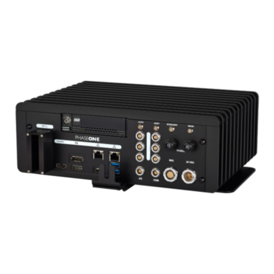
iX Controller MK 5 Installation and Operation Guide 3. Overview Figure 2. iX Controller MK 5 - Rear Panel 1. Satellite Tracking LED 3. PPS Output 2. Antenna Connector 3.1.1 iX Controller MK 5 Power Overview The iX Controller MK 5 is powered from a source that meets the following specifications: •... -
Page 10: Configuration Options
iX Controller MK 5 Installation and Operation Guide 3. Overview Configuration Options The iX Controller MK 5 with its internal GNSS supports connection to the following IMUs for a range of orientation accuracies: • Applanix IMU 79 - internal • Applanix IMU 69 - external •... -
Page 11: Connecting Cables And Peripherals
iX Controller MK 5 Installation and Operation Guide 4. Connecting Cables and Peripherals 4 Connecting Cables and Peripherals iX Controller MK 5 Power Cable (P/N 70348000) Table 2 lists the iX Controller MK 5 power requirements. Table 2 iX Controller MK 5 System Power Requirements Parameter Requirement Voltage... -
Page 12: Controller/Ix Camera Power Cable (P/N 70364000)
iX Controller MK 5 Installation and Operation Guide 4. Connecting Cables and Peripherals To connect the iX Controller MK 5 power cable: 1. Connect the aircraft power cable with the LEMO connector to the iX Controller MK 5 28 VDC port. Figure 4. -
Page 13: Controller Mk 5 To Camera I/O Cables (P/N 70378000)
iX Controller MK 5 Installation and Operation Guide 4. Connecting Cables and Peripherals 4.3 iX Controller MK 5 to Camera I/O Cables (P/N 70378000) The iX Controller MK 5 to camera I/O cable transfers trigger, black reference and MEP signals between the iX Controller MK 5 and the camera. -
Page 14: Controller Mk 5 To Camera Usb 3.0 Cables
iX Controller MK 5 Installation and Operation Guide 4. Connecting Cables and Peripherals 4.4 iX Controller MK 5 to Camera USB 3.0 Cables The iX Controller MK 5 to camera USB cable (supplied with each camera) transfers control data from the iX Controller MK 5 and the camera, and images from the camera for storage in the iX Controller MK 5. - Page 15 iX Controller MK 5 Installation and Operation Guide 4. Connecting Cables and Peripherals Figure 7 shows power and communication connections for the pilot and operator monitors. Figure 7. Monitor Connections To connect the pilot monitor: 1. Connect the cable end with 2 connectors to the pilot monitor power and video ports (video cable includes USB signal).
-
Page 16: Keyboard And Mouse
iX Controller MK 5 Installation and Operation Guide 4. Connecting Cables and Peripherals 4.6 Keyboard and Mouse To connect a keyboard and mouse to the iX Controller MK 5: 1. Using a 2.5 mm hex key, remove both screws securing the USB 3.0 cable bracket front plate to the cable bracket bottom plate. -
Page 17: External Imu
iX Controller MK 5 Installation and Operation Guide 4. Connecting Cables and Peripherals 2. Remove both screws securing the cable bracket bottom plate to the iX Controller MK 5. For USB cables with short hoods 3. Mount the cable bracket bottom plate to the iX Controller MK 5 using the holes near the bottom plate edge. -
Page 18: Pps Output
iX Controller MK 5 Installation and Operation Guide 4. Connecting Cables and Peripherals To connect an external IMU to the iX Controller MK 5: 1. Connect one end of the IMU cable to the IMU. 2. Connect the other end of the IMU cable to the iX Controller MK 5 IMU port. 4.8 PPS Output The internal GNSS provides a pulse-per-second (PPS) time synchronization output mark. -
Page 19: Powering Up The Ix Controller Mk 5
2. When the Windows 10 login window appears, log in using the following credentials: User name: user No password required. Note To remotely login to the iX Controller MK 5, see How to Connect Remotely to iX Controller available for download at https://industrial.phaseone.com/downloads-guides.aspx Page 19 of 36... -
Page 20: Controller Mk 5 Storage
iX Controller MK 5 Installation and Operation Guide 6. iX Controller MK 5 Storage 6 iX Controller MK 5 Storage Disk Management The iX Controller MK 5 storage consists of a built-in frame with a removable carrier containing two SSD drives. -
Page 21: Removing The Ssd Drive Carrier
iX Controller MK 5 Installation and Operation Guide 6. iX Controller MK 5 Storage 6.3 Removing the SSD Drive Carrier An additional frame is provided with the iX Controller MK 5. This frame should be installed in a computer used for post-flight processing. You can then transfer the carrier with its SSD drives between the iX Controller MK 5 and the processing computer. -
Page 22: Operating The Ix Controller Mk 5
2. Follow instructions for setup and use of iX Capture as described in the iX Capture User Guide on the USB drive provided with iX Controller MK 5, and available for download at: https://industrial.phaseone.com/downloads-guides.aspx Using iX Flight 1. If you purchased a license for iX Flight, on the operator panel desktop, double-click iX Flight. -
Page 23: Shutting Down The Ix Controller Mk 5
iX Controller MK 5 Installation and Operation Guide 8. Shutting Down the iX Controller MK 5 8 Shutting Down the iX Controller MK 5 To shut down the iX Controller MK 5: 1. Perform a standard Windows 10 shutdown. 2. Pull out the Main and Auxiliary circuit breakers. Page 23 of 36... -
Page 24: Troubleshooting
iX Controller MK 5 Installation and Operation Guide 9. Troubleshooting 9 Troubleshooting Issue Solution Cannot close iX Capture with mouse. On the keyboard, press Alt+F4. iX Controller MK 5 MAIN Power LED is on, Pull out the Main circuit breaker and push it back in. but Windows 10 does not appear. -
Page 25: Maintenance
iX Controller MK 5 Installation and Operation Guide 10. Maintenance 10 Maintenance 10.1 Replacing SSD Drives The iX Controller MK 5 is factory provided with two 1 TB SSD drives installed in a removable carrier. You can replace the SSDs as required. To achieve optimal performance, both SSDs should have a high writing speed (>500 MB/S). -
Page 26: Appendix A Configuring The Applanix Gnss
iX Controller MK 5 Installation and Operation Guide Appendix A. Configuring the Applanix GNSS Appendix A Configuring the Applanix GNSS Note The iX Controller MK 5 contains a GNSS which can be used if you purchase the GNSS option from Phase One. - Page 27 iX Controller MK 5 Installation and Operation Guide Appendix A. Configuring the Applanix GNSS 2. Configure the parameters as shown following: Parameter Setting Enable Selected. Schedule Continuous. Measurement Interval 0.1 Sec. Position Interval 0.01 Sec. Log Received Corrections Selected. Log SBAS Data Selected.
-
Page 28: Configuring The Receiver
iX Controller MK 5 Installation and Operation Guide Appendix A. Configuring the Applanix GNSS Configuring the Receiver A.2.1 Tracking 1. In the menu, under Receiver Configuration, click Tracking and configure the outlined parameter as shown following: Parameter Setting SBAS L1 - C/A Unselected. -
Page 29: General
iX Controller MK 5 Installation and Operation Guide Appendix A. Configuring the Applanix GNSS A.2.3 General 1. In the menu, under Receiver Configuration, click General and configure the parameters as shown following: Parameter Setting Enable Shared Port Serial 3 Event 1 On/Off Enable Event 1 Slope Negative... -
Page 30: Ins
iX Controller MK 5 Installation and Operation Guide Appendix A. Configuring the Applanix GNSS A.2.4 Note Configure the INS if you are using the IMU located inside the iX Controller MK 5. When using an external IMU, see Section A.2.5 - External IMU. 1. - Page 31 iX Controller MK 5 Installation and Operation Guide Appendix A. Configuring the Applanix GNSS When measuring the IMU lever arm, use the iX Controller MK5 right aft screw head center as Note a reference point. The following measurements are from the screw head center to the internal IMU measurement center in a controller coordinate system (shown below): •...
-
Page 32: External Imu
iX Controller MK 5 Installation and Operation Guide Appendix A. Configuring the Applanix GNSS A.2.5 External IMU Note Configure the External IMU if you are using an external IMU. When using the IMU located inside the iX Controller MK 5, see Section A.2.4 - INS 1. -
Page 33: External Sensor Control
iX Controller MK 5 Installation and Operation Guide Appendix A. Configuring the Applanix GNSS A.2.6 External Sensor Control Configure the stabilizer control in the External Sensor Control window: 1. In the menu, under Receiver Configuration, click External Sensor Control and configure the outlined parameter as shown following: Note The following configuration is for controlling the SOMAG stabilizer through Applanix GNSS. -
Page 34: Configuring I/O Ports
iX Controller MK 5 Installation and Operation Guide Appendix A. Configuring the Applanix GNSS Configuring I/O Ports Note The configuration shown here is for controlling the SOMAG stabilizer through Applanix GNSS. A.3.1 Serial COM1 - Gimbal Settings For Systems Using SOMAG CSM40/DSM400 Stabilizers controlled by iX Flight: 1. -
Page 35: Serial Com2 - Camera
iX Controller MK 5 Installation and Operation Guide Appendix A. Configuring the Applanix GNSS A.3.2 Serial COM2 – Camera 1. In the menu, under I/O Configuration, click Port Configuration and configure the parameters as shown following: Parameter Setting NMEA Legacy Selected 2. -
Page 36: Tcp 5018 - Nmea For Ix Flight
iX Controller MK 5 Installation and Operation Guide Appendix A. Configuring the Applanix GNSS A.3.3 TCP 5018 - NMEA for iX Flight 1. In the menu, under I/O Configuration, click Port Configuration and configure the parameters as shown following: Parameter Setting 20 Hz 20 Hz...
Need help?
Do you have a question about the iX MK 5 and is the answer not in the manual?
Questions and answers