Table of Contents
Advertisement
Quick Links
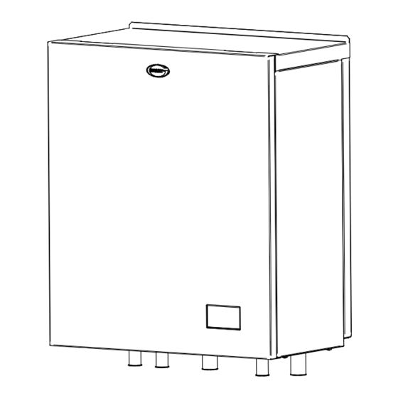
Grant EvoLink
Hybrid System Hub
Installation Instructions
THESE INSTRUCTIONS SHOULD BE READ IN CONJUNCTION WITH THE
EVOLINK_FINAL_ASM_V4.asm
REV DISCRIPTION:
18/05/23
JOB TITLE:
DRAWING TITLE:
DWG NO:
REV:
REV DATE:
DATE:
XXXXXXXXXXX
INSTALLATION AND SERVICING INSTRUCTIONS SUPPLIED WITH THE
AERONA³ AND ANY OTHER HEATING APPLIANCES USED.
UK | DOC 0200 | Rev 1.2 | February 2024
Advertisement
Table of Contents

Related Manuals for Grant EvoLink


Summary of Contents for Grant EvoLink
- Page 1 Grant EvoLink Hybrid System Hub Installation Instructions THESE INSTRUCTIONS SHOULD BE READ IN CONJUNCTION WITH THE EVOLINK_FINAL_ASM_V4.asm REV DISCRIPTION: 18/05/23 JOB TITLE: DRAWING TITLE: DWG NO: REV: REV DATE: DATE: XXXXXXXXXXX INSTALLATION AND SERVICING INSTRUCTIONS SUPPLIED WITH THE AERONA³ AND ANY OTHER HEATING APPLIANCES USED.
- Page 2 This manual is accurate at the date of printing but will be superseded and should be disregarded if specifications and/or appearances are changed in the interests of continued product improvement. However, no responsibility of any kind for any injury, death, loss, damage or delay however caused resulting from the use of this manual can be accepted by Grant Engineering (UK) Limited, the author or others involved in its publication.
-
Page 3: Table Of Contents
Contents INTRODUCTION General How it works Touchscreen user interface Product Contents TECHNICAL DATA EvoLink Technical Data Dimensions INSTALLATION General Regulations and Standards Location Clearances Metering System cleaning Pipe connections EvoLink installation Installation procedure ELECTRICAL General Electrical connections Electrical supply Boiler demand 7-Day immersion programmer (legionella) Aerona³... -
Page 4: Introduction
As the outdoor air temperature changes, so will the heat demand and thus the required flow water temperature, up to the maximum The Grant EvoLink is a unique means of utilising a Grant Aerona³ ‘Heating Setpoint’ value. air source heat pump with an existing wet domestic heating... -
Page 5: Technical Data
2 Technical Data EVOLINK TECHNICAL DATA Table 2-1: EvoLink technical data Property Value Weight - empty 29kg Weight - full 38kg Water content 9 litres Power supply 230V~ 1ph 50Hz Connections - heating system 28mm copper Connections - heat pump... -
Page 6: Installation
The Grant EvoLink is enclosed in a wall mounted casing designed to be installed internally. The wall onto which the EvoLink is to be fixed must be flat, vertical and of a suitable construction firm enough to support the weight of the unit. -
Page 7: Evolink Installation
Remove the wall fixing plate from the packaging. connection to the Aerona³ air source heat pump. Refer to • Position the wall fixing plate on the wall where the EvoLink is Section 4 of these instructions. to be installed with the outward facing edge at the top. -
Page 8: Electrical
Boiler demand connection block - pre-wired to terminal block temperature sensor and system return sensor, are contained 2 from factory. within the EvoLink casing. The control PCB is located inside an Supplementary circulating pump connection block. electrical enclosure located on the base panel inside the EvoLink Notes: casing. -
Page 9: Electrical Supply
2 are factory wired to the 'volt free' boiler control relay on the EvoLink PCB so that when this closes, the volt free with the programmer. switching starts the boiler. -
Page 10: Aerona³ Air Source Heat Pump
– refer to Figure 4-1 located below the right corner of the EvoLink PCB. The outdoor air temperature sensor can be mounted directly onto an external wall, but positioned so that it is not in direct sunlight at To connect the Aerona³... -
Page 11: System Return Temperature Sensor
A two-core cable is required to connect the sensor to the EvoLink A 230V 50Hz output is available to operate the pump whenever terminal block. Two cores of a multi core alarm cable can be used there is a demand from the 'Supplementary Boiler Demand' but it must have a minimum external diameter between 3 and 6.5... -
Page 12: System Wiring Diagrams - Switch Live Demand - Heating Only Boiler
Checked By: NS This drawing and its content is subject to copyright. Use other than for its original intended purpose must be arranged with an employee of Grant UK Ltd. Blagrove Industrial Estate, Swindon, Wiltshire, SN8 5YG, tel; 01380 736920... -
Page 13: System Wiring Diagrams - Switch Live Demand - Combi Boiler
Checked By: NS This drawing and its content is subject to copyright. Use other than for its original intended purpose must be arranged with an employee of Grant UK Ltd. Blagrove Industrial Estate, Swindon, Wiltshire, SN8 5YG, tel; 01380 736920... -
Page 14: System Wiring Diagrams - Volt Free Switching - Heating Only Boiler
This drawing and its content is subject to copyright. Use other than for its original intended purpose must be arranged with an employee of Grant UK Ltd. Blagrove Industrial Estate, Swindon, Wiltshire, SN8 5YG, tel; 01380 736920 Figure 4-4: EvoLink System Wiring Diagram - S-Plan type system - volt free switching - heating only boiler Page 14 Section 4: Electrical... -
Page 15: Evolink Operation
Clipped to boiler Flow pipe EvoLink Flow temperature sensor Clipped to EvoLink Flow pipe Boiler ASHP System flow System return System Return temperature sensor Clipped to system return pipe Figure 5-1: EvoLink Hydraulic Schematic Diagram Section 5: EvoLink Operation Page 15... -
Page 16: Operation
5.2.2 HOT WATER • If there is a hot water demand to the EvoLink, i.e., if both The EvoLink controls the operation of both the heat pump and the the hot water channel of the programmer and the cylinder supplementary heat source (boiler). -
Page 17: Manual Override Operation
The Grant EvoLink control system includes a manual controls: override function, operated via the touch screen user interface. IMPORTANT. To use the following the EvoLink MUST be first • By using this function the EvoLink control can be manually be set to standby. -
Page 18: Evolink Parameters
It is a pseudo integral timer. This allows manual selection of the supplementary heat source. The EvoLink will use the heat pump as its primary heat source. OVERRIDE MODE The EvoLink will use the supplementary heat source as its primary heat source. -
Page 19: Commissioning
In order to commission the EvoLink installation, the Access to check, adjust and set the operating parameters for following information must be used in conjunction with the EvoLink system. Refer to section 5.5, 6.4 and Figures 6-1 the Aerona³ installation instructions supplied with the heat & 6-2. -
Page 20: Parameter Settings
The display will return to the weather compensation screen. PARAMETER SETTINGS When all four weather compensation parameters are correct: The EvoLink operating parameters are accessed and set using Tap the ON/OFF icon so 'ON' is displayed. the touch screen user interface. Refer to Figure 6-1. -
Page 21: Override Function
Set the TIME BELOW SP AUTO CH Set the OUTSIDE TEMP BOILER ONLY Tap the + or – icons to adjust the TIME BELOW SP AUTO value Tap the + or – icons to adjust the OUTSIDE TEMP BOILER ONLY as required. -
Page 22: User Interface Display Screen
USER INTERFACE DISPLAY SCREEN Page 22 Section 6: Commissioning... -
Page 23: Grant Evolink Settings
SUPPLEMENT DHW TYPE Boiler / Element Inoperative Record all EvoLink parameter/function settings that have been changed during commissioning in the 'Setting' column in the above table. *Refer to Table 5-1 for more detailed information about these parameters. Section 6: Commissioning... -
Page 24: Weather Compensation Settings
WEATHER COMPENSATION SETTINGS The four values for weather compensation set on the EvoLink (parameters 15, 16, 17 and 18 in Table 6-1) must be the same as the corresponding weather compensation values set on the Aerona³ air source heat pump. Refer to Table 8-3 and the installation instructions supplied with the Aerona³... -
Page 25: Declaration Of Conformity
Responsible Person: Mr. Adrian Rice Position: Controls Manager Signature: ________________________________ Date: 13th July 2023 Registered Office: Crinkle, Birr, R42 D788, Co. Offaly, Ireland Registered Number: 143329 DIRECTORS STEPHEN GRANT, MAURA GRANT, NIALL FAY Section 7: Declaration of Conformity Page 25... -
Page 26: Ukca Declaration Of Conformity
This declaration is made under the sole responsibility of the following Manufacturer. The Manufacturer declares that the following product conforms to the requirements of the UK Legislation and Regulations as detailed below. Grant Engineering (UK) Limited Unit A/B, Europark Frankland Road... -
Page 27: Health And Safety Information
SEALANT AND ADHESIVE The Health and Safety information given in this section relates to Material Types: the EvoLink only. Paste - a mixture of saponified mineral and vegetable oils and For details of the Health and Safety Information for the heat inert mineral powders. -
Page 28: Guarantee
This will be extended to a total period of two years if the EvoLink hybrid system hub is registered with Grant Engineering (UK) The following documents must be made available to Grant... - Page 29 The replacement of an EvoLink hybrid system hub under this guarantee does not include any consequential costs. • The EvoLink hybrid system hub must not be sited in a location where it may be subjected to frost. Section 9: Guarantee...
-
Page 30: Notes
Notes Page 30 Notes... - Page 31 Notes Notes Page 31...
- Page 32 GRANT ENGINEERING (UK) LIMITED Frankland Road, Blagrove Industrial Estate, Swindon, Wiltshire, SN5 8YG Tel: +44 (0)1380 736920 Fax: +44 (0)1380 736991 Email: info@grantuk.com www.grantuk.com...
Need help?
Do you have a question about the EvoLink and is the answer not in the manual?
Questions and answers