
Related Manuals for Andor Technology Oxford Instruments Laser-Lock


Summary of Contents for Andor Technology Oxford Instruments Laser-Lock
- Page 1 Laser-Lock Class 4 Laser Product Interlock Combiner Version 1.1 rev 16 January 2024 User Guide andor.oxinst.com © Andor Technology Ltd. 2024...
-
Page 2: Table Of Contents
Contents Section 1: Introduction ..........................6 Technical Support ..............................7 Disclaimer ..................................8 Copyright and Protective Notices ........................8 Trademarks and Patent Information ......................8 Supplied Components .............................9 Section 2: Product Overview .......................10 Interlock Safety System ............................10 Laser-Lock Functions ............................10 2.2.1 Laser-Lock Fascia Interface ..............................11 2.2.2 Laser-Lock Rear Panel Interface ............................11... - Page 3 Section 4: Operation ..........................17 Emergency Mains Disconnection ........................17 Power Up ..................................17 4.2.1 Microscope Interlock Opened ..............................17 4.2.2 Remote Interlock Opened ...............................17 Power Down ................................. 17 Section 5: Maintenance ......................... 18 Cleaning and Decontamination ........................18 Regular Checks ................................18 Annual Electrical Safety Checks ........................18 Section 6: Troubleshooting ........................
- Page 4 Revision History Version Released Description 25 February 2022 Initial release. Updated laser-lock mechanical drawings and product images. Updated connection 16 January 2024 diagram and interlock LED instructions. Updated Japan office contact information. Updates to the Manual Changes are periodically made to the product and these will be incorporated into new editions of the manual. Please check for new releases of the manual at: andor.oxinst.com/downloads.
- Page 5 Safety and Warning Information PLEASE READ THIS INFORMATION FIRST CAUTION – USE OF CONTROLS OR ADJUSTMENTS OR PERFORMANCE OF PROCEDURES OTHER THAN THOSE SPECIFIED HEREIN MAY RESULT IN HAZARDOUS RADIATION EXPO- SURE. If the equipment is used in a manner not specified by Andor, the protection provided by the equipment may be impaired.
- Page 6 Electromagnetic Compatibility (EMC) – Caution: This product was designed for and tested using the IEC/EN 61326-1 EMC standard for Class A emissions and a Basic immunity environment. Class A means that it is not designed for a domestic or residential environment, and Basic immunity refers to the fact that it is not designed for a typical industrial environment.
-
Page 7: Section 1: Introduction
Section 1: Introduction The Laser-Lock is an important component of your laser microscopy system; designed to prevent accidental exposure to laser radiation, it serves as the main interface between interlock devices. When used as part of a laser product, the Laser-Lock unit provides compliance with IEC 60825-1 and CDRH regulations requiring manual reset functionality for Class 4 laser systems. -
Page 8: Technical Support
1.1 Technical Support If you have any questions regarding the use of this equipment, please contact the representative* from whom your system was purchased, or: Europe Andor Technology Ltd. Andor Technology 7 Millennium Way 300 Baker Avenue Springvale Business Park... -
Page 9: Disclaimer
Andor Technology or any third party. 1.4 Trademarks and Patent Information Andor and the Andor logo and are trademarks of Andor Technology Ltd. Andor Technology Ltd is an Oxford Instruments company. All other marks are property of their owners. -
Page 10: Supplied Components
1.5 Supplied Components The Laser-Lock box is provided as part of an installed system, connection cables and interlock fittings appropriate for your order will be provided and installed by our installation engineers. Description Quantity Laser-Lock box External AC/DC power User guide supply with region-specific (in electronic format) mains plugs... -
Page 11: Section 2: Product Overview
Section 2: Product Overview 2.1 Interlock Safety System The Interlock System comprises of a set of switches which are used to detect the state and configuration of the Microscopy System including the Microscope Eyepiece prism, the transmitted light arm on inverted microscopes and the presence of a stage cover if one is installed. -
Page 12: Laser-Lock Fascia Interface
2.2.1 Laser-Lock Fascia Interface Figure 1: Front of the Laser-Lock Box, has the power LED and the key switch. 2.2.2 Laser-Lock Rear Panel Interface Figure 2: Image of connection plate of Laser-Lock Box, from left to right, USB power connector, remote interlock, microscope inter- lock, 4x product interlock connectors. -
Page 13: Laser-Lock Top Panel Interface
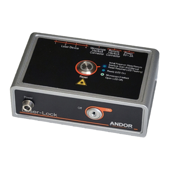
2.2.3 Laser-Lock Top Panel Interface Figure 3: Laser lock box top panel view with solid blue LED indicating Ready (LED on). 2.3 Function of Controls and Indicators 2.3.1 Key Switch The system can only be powered on with the use of the Key Switch. The mechanism of the Key Switch is such that the key cannot be removed from the switch when it is in the ON position. -
Page 14: Section 3: Installation
Section 3: Installation This product is supplied as part of a system, and must be installed by an Andor Installation Technician or a trained Andor Systems distributor. The following is only provided to augment this. 3.1 Laser-Lock Installation 3.1.1 Location and Mounting The Laser-Lock must be placed where it can be easily seen and accessed by the user. -
Page 15: Interlock Cable Installation
3.2 Interlock Cable Installation • Do not pull cables by the sheath but use the connector body. • Most of the interlock cables will be installed by trained Andor support staff, but the following information is provided to familiarise the user with all of the connections. 3.2.1 Microscope Interlock Connector •... -
Page 16: Remote Interlock Connector
3.2.2 Remote Interlock Connector • The Remote Interlock Connector is a requirement of IEC 60285-1 and the CDRH Regulations for Class 3B and Class 4 laser products. • Remote interlocks are remote from the laser products as opposed to being local to the products themselves, e.g. -
Page 17: Typical System Configurations
3.3 Typical System Configurations version 1.1 rev 16 January 2024... -
Page 18: Section 4: Operation
Section 4: Operation 4.1 Emergency Mains Disconnection In case of emergency, the disconnect as follows: SWITCH OFF THE POWER AT THE MAINS SOCKET AND REMOVE THE MAINS LEAD FROM THE EXTERNAL POWER SUPPLY 4.2 Power Up Turn the key clockwise until the green power LED illuminates. Ensure interlocks are closed. -
Page 19: Section 5: Maintenance
Section 5: Maintenance Important: The system should be powered down prior to performing any maintenance checks. 5.1 Cleaning and Decontamination To clean the product, only use a damp lint-free cloth. Do not wet the connectors. Do not use solvents, cleaning agents, or aerosols. -
Page 20: Section 6: Troubleshooting
Section 6: Troubleshooting If the Laser-Lock box is provided as part of system with a HLE, ILE, Dragonfly, or other laser product, please refer to the troubleshooting sections of their respective user guides, available at andor.oxinst.com/downloads. version 1.1 rev 16 January 2024... -
Page 21: Appendix A: Technical Specifications
Appendix A: Technical Specifications Environmental Specifications Laser-Lock Box Location to be used Indoor Altitude Up to 2000 m Operating temperature 0°C to 45°C Storage temperature -20°C to 70°C Operating relative humidity <70% (non-condensing) Pollution degree 2. Normally only non-conductive pollution occurs. Occasionally, Pollution degree however, a temporary conductivity caused by condensation must be expected. - Page 22 Electrical Power Specifications Laser-Lock Box Mains Input for Supplied External Power Supply 100 - 240 V AC, 50 - 60 Hz ± 3Hz Laser-lock only 0.61 W Power Consumption Laser-lock + external power supply 0.82 W Voltage Rating 5 V DC Power Current Rating CAT II An overvoltage category of CAT II means that the equipment is designed to Mains Overvoltage Category...
-
Page 23: Appendix B: Mechanical Drawings
NOTE: ALL MATERIAL AND FINISHING PROCESSES MUST NOTICE: THE INFORMATION CONTAINED IN THIS COMPLY WITH RoHS AND COSHH REGULATIONS DRAWING IS PROPRIETARY TO ANDOR TECHNOLOGY AND SHALL NOT BE DISCLOSED IN WHOLE OR IN PART OR MATERIAL USED FOR ANY DESIGN OR MANUFACTURE EXCEPT WHEN... -
Page 24: Appendix C: Other Information
Appendix C: Other Information C.1 Terms and Conditions of Sale and Warranty Information The terms and conditions of sale, including warranty conditions, will have been made available during the or- dering process. The current version for the US is available here, for all other regions (except Japan) please click here. -
Page 25: Appendix D: China Rohs Hazardous Substances Declaration
Appendix D: China RoHS Hazardous Substances Declaration Name and Content of Hazardous Substances in the Product 产品中有害物质的名称及含量 产品中有害物质的名称及含量 Hazardous Substance: 有害物质 Polybromi- Chromium VI nated Diphenyl Lead Mercury Cadmium Compounds Biphenyls Ethers Component Name 部件名称 (Pb) (Hg) (Cd) (PBB) (PBDE) 铅...
Need help?
Do you have a question about the Oxford Instruments Laser-Lock and is the answer not in the manual?
Questions and answers