
Subscribe to Our Youtube Channel
Related Manuals for Andor Technology Dragonfly 500


Summary of Contents for Andor Technology Dragonfly 500
- Page 1 Dragonfly 500 Version 1.5 revised 20 December 2018 Hardware Guide andor.com © Andor Technology Ltd. 2018.
-
Page 2: Table Of Contents
Outline of the Functionality of Imaging Modes* ............21 SYSTEM CONFIGURATIONS ....................23 MICROSCOPE REQUIREMENTS ..................23 CAMERA ORIENTATION REQUIREMENTS ................23 EXTERNAL FEATURES OF THE DRAGONFLY 500 ............... 24 2.5.1 Connections Panel and Status Display ..............25 2.5.2 Power Supply ......................26 2.5.3... - Page 3 Hazards Due to Moisture or Liquids ................ 33 USING THE DRAGONFLY 500 ....................34 4.5.1 Stage Cover....................... 34 4.5.2 Controlling the Dragonfly 500 through the Software ..........34 ADDITIONAL PROCEDURES ....................35 4.6.1 Removal of the Emission Filter Wheel ..............35 4.6.2 Insertion of the Emission Filter Wheel ..............
- Page 4 Dragonfly 500 APPENDIX A: MECHANICAL DRAWINGS ..................54 APPENDIX B: GLOSSARY ........................55 APPENDIX C: OTHER INFORMATION ....................56 Version 1.5 rev 20 Dec 2018...
- Page 5 Added Camera XY adjustment procedure (Section 4.6.5) Added references to check MyAndor for further information. Updated references to Dragonfly as Dragonfly 500. (For Dragonfly 200 refer to the Dragonfly 200 manual). Further detail added to Camera XY adjustment procedure (Section 4.6.5) 08 Mar 2018 Information added regarding interlock system (Section 2.5.3)
- Page 6 15. Locate the laser source, Dragonfly 500 and any other components connected via fibre optic cables within 2 m of each other so that the interconnecting fibres are not stretched, bent, or constrained.
- Page 7 Dragonfly 500 17. Performance of the system may be adversely affected by rapidly changing environmental conditions or operation outside of the operating conditions specified in SECTION 7 “TECHNICAL SPECIFICATIONS”. 18. Electromagnetic Compatibility: This is a Class A product. In a domestic environment this product may cause electromagnetic interference, in which case the user may be required to take adequate measures.
- Page 8 The Dragonfly 500 does not contain any embedded laser sources but it is intended to be integrated with a compatible laser source and has therefore been designed to safely accept, and handle laser radiation. The Dragonfly 500 unit and all ancillary components of the Dragonfly 500 system have been designed and labelled to be compliant with IEC 60825-1 and CDRH Title 21 CFR 1040.10.
- Page 9 The Dragonfly 500 may be configured as part of a larger system that includes multiple Class 3B and Class 4 lasers. A number of separate emission wavelengths can also be available in any one system. In some very rare occasions another classification label may be used, this will be explained in additional documentation if this is required.
- Page 10 The access panels are labelled with Laser Classification / Explanatory Labels- as described later in this section. If the Dragonfly 500 is to be re-classified by a site’s trained and competent individual (e.g. the site’s Laser Safety Officer) then they must ensure that labels of the correct classification and wavelength range are placed in all of the locations.
- Page 11 Dragonfly 500 Uidelines for peration of aser rodUcts Read the safety instructions supplied with all equipment in the system. Never look into a laser beam either directly, or indirectly. Do not attempt to disassemble the unit housing the lasers or any part of the system. If there a problem is suspected, please contact Andor directly (see Section1.1, “Help and Technical Support”).
- Page 12 Dragonfly 500 nforMation on iewing pertUres In order to view any of the apertures, it is necessary to use eye protection to reduce the intensity of the laser power to acceptable levels for viewing. The table below provides the appropriate OD values required for each wavelength.
- Page 13 Dragonfly 500 PRODUCT INFORMATION AND WARNING LABELLING This section highlights the location and description of the product information and warning labels of the Dragonfly 500. roduct omPliance and nformation abels Connections Panel Label (see Section 2.5.1) Standby Button Label (see Section 2.5.2) Figure 1: Product Compliance and Information Label (Connections Panel and Standby Button labels also shown) This label indicates the product compliance with the applicable standards.
- Page 14 Figure 3: The Port Selection Mirror Access Label This label highlights the potential Dichroic Access Door Crush Hazard and information for the installed Dichroics. Power Off the Dragonfly 500 before accessing the Camera Splitter dichroic slider. Please see Section 4.6. ilter...
- Page 15 Dragonfly 500 ervice ccess anel abels The above label highlights the accessible laser hazard (in Note: Units without TIRF module also this example Laser Class 3B) have warning on the blanking panel if the panels are removed. (requires tooled removal)
-
Page 16: Section 1: Introduction
Dragonfly 500 INTRODUCTION SECTION 1: INTRODUCTION 1.1 t echnical Upport If you have any questions regarding the use of this equipment, please contact the representative* from whom your system was purchased, or: Europe Andor Technology Ltd. Andor Technology 7 Millennium Way... -
Page 17: Disclaimer
The copyright in this document and the associated drawings are the property of Andor Technology Ltd. and all rights are reserved. This document and the associated drawings are issued on condition that they are not copied, reprinted or reproduced, nor their contents disclosed. -
Page 18: Supplied Components
Upplied oMponents The Dragonfly 500 system may be supplied in different configurations along with components and accessories required for your specific application. Please refer to your ordering information and check the packing list to confirm that all parts are present. -
Page 19: Optional Components
Notes: • Andor provide a range of other microscopy system components that can be configured with or alongside Dragonfly 500. Please contact your nearest Andor Sales representative for further information on these other system accessories. • Use only accessories supplied and recommended by Andor (except for the AC/DC Power Supply, which must meet the specification of Section 7.3, and mains cables, which must be certified for the country of use). -
Page 20: Section 2: Product Overview
The Dragonfly 500 is shown as part of an integrated system in the diagram of Figure 9. Laser light from an Integrated Laser Engine (ILE) is fed as an input into one port of the Dragonfly 500 via a multi-mode optical fibre for widefield and confocal illumination (passing first through a Borealis Beam Conditioning Unit –... -
Page 21: Outline Of The Functionality Of Imaging Modes
M6 or imperial ¼”-20 screw holes. The minimum recommended table benchtop size is 122 x 92 cm [48 x 36 inches] approx. For laser safety reasons, the Dragonfly 500 should only be aligned and interlocked to the microscope by a qualified Andor representative. - Page 22 Dragonfly 500 PRODUCT OVERVIEW Camera Relative illum. Field of view Min Disk Area Illum. Magnification Comments Power Density (mm) Dimensions (mm) (nominal) 16.64x14.04 Neo&Zyla 5.5 (2560x2160 sCMOS) - Full frame 16.64x14.04 Neo&Zyla 5.5 (2160x2160 sCMOS) – Scope Quality Area 14.04x14.04 14.04x14.04...
-
Page 23: System Configurations
The RIFD Tag can be updated by the User via the Dragonfly 500 Control software if the emission filters loaded in a Filter Wheel are changed. -
Page 24: External Features Of The Dragonfly 500
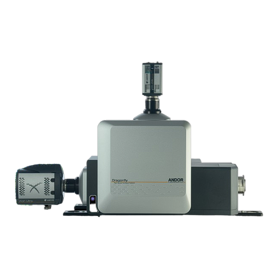
The main external features and modules of the Dragonfly 500 are shown below- with 2 cameras mounted to the side and top camera ports (Installation handles are removed after installation). Fibre Ports Camera Port 1... -
Page 25: Connections Panel And Status Display
See Section 7.3 for specification. The USB port connects the Dragonfly 500 to a PC workstation over a USB link allowing the Dragonfly 500 to be fully controlled through the image acquisition control software on the PC (do not connect RS232 if controlling via USB). -
Page 26: Power Supply
This port is connected to the port marked W2 on the filter wheel controller with the supplied cable. This allows filter wheel 2 to be controlled. RS232 FW out This port is connected to the port marked RS-232 on the filter wheel controller to allow Dragonfly 500 to effect control of the filter wheels. RS232 PC This port connects the Dragonfly 500 to a PC workstation over an RS232 link allowing Dragonfly 500 to be fully controlled from the PC (do not connect USB if controlling via RS232). -
Page 27: Laser Safety Interlock System
The Dragonfly 500 is interlocked as part of a laser safety interlock system with external equipment such as a laser source, microscope or door interlock. The System Interlock connection of the Dragonfly 500 is located on the connection panel (See Section 2.2.1). The internal interlock system of the Dragonfly 500 consists of switches in the main filter wheel internal door (not the external cosmetic panel) and switches in the Disk Dichroic Access Panel (service access only). -
Page 28: Interlock Summary Diagram
Dragonfly 500 INSTALLATION 2.5.3.1 i nterlock eVel UMMary iagraM Notes Laser Source: The Dragonfly features internal interlocks (Section 2.5.3) e.g. and the interlock system is extended to the other connected devices. If any of the interlocks is activated laser emission •... -
Page 29: Section 3: Installation
Operational vibrations should be reduced as much as possible for stability of the imaging train. • It is recommended that the Dragonfly 500 is mounted on a damped optical table (minimum dimensions: 122 x 92 cm [48 x 36 inches approx.). Please contact your Andor Representative for assistance in specifying and ordering a suitable table. -
Page 30: Transport And Storage
• Store between 0°C to 50°C. • If the Dragonfly 500 needs to be transported, or moved to a different location please contact Andor customer support for further instructions. • The Dragonfly 500 has handles to aid lifting and positioning of the unit during installation (shown below). These are removed after installation and must be kept in a safe place in case they are needed at a later time. - Page 31 Dragonfly 500 OPERATION The standard Ophir PD-300W-W sensor and power meter can be used to assess accessible power levels in conjunction with suitable safety glasses and applicable Safe Systems of Work. Any queries should be referred to the Andor Product Laser Safety Officer for guidance.
-
Page 32: Section 4: Operation
Turn on the system camera(s) (refer to the supplied manual). Turn on the filter wheel controller (refer to the supplied manual). Turn on the microscope and associated external devices (refer to the supplied manuals). Turn on the Dragonfly 500. On/Off switch located on left side... -
Page 33: Power-Down Sequence
NOTE: This will send all of the device’s motorised stages to their parked positions, allow time for all stages to complete their motion before proceeding to step 2, this will be clearly audible. Turn off the Dragonfly 500 by switching the rocker switch on the left side panel to OFF. Turn off the ILE. -
Page 34: Using The Dragonfly 500
Additional technical notes and useful information to help you get the best from your Dragonfly 500 system will be made available from MyAndor, please check the Technical Notes section in case there is further relevant information that is not covered in the scope of this manual 4.5.1 s... -
Page 35: Additional Procedures
The Emission Pathway panel is interlocked to the laser source (ILE) such that if the panel is opened while the ILE is on, the flow of laser light into the Dragonfly 500 unit will be cut off (see Section 2.5.3). - Page 36 Dragonfly 500 OPERATION 2. The Magnification Slider Aperture Hazard (marked in blue below) could be accessible through the T-shaped chamber after either filter wheel was removed. There are hazardous mechanisms - above for the vertical filter wheel, or to the left for the horizontal filter wheel, that could move and hurt fingers if they were placed in this circular aperture.
- Page 37 10. Insert, remove, or replace any desired emission filters in the filter wheel, or prepare a second alternative loaded filter wheel to be put into the Dragonfly 500 unit. Refer to Section 4.6.3 for filter changing procedure. 11. Follow the steps in Section 4.6.2 to re-insert the filter wheel or insert a second alternative filter wheel.
-
Page 38: Insertion Of The Emission Filter Wheel
Close the square front access panel cover. Push the cover in until it snaps into the fully closed position. If the filter wheel that has been inserted into the Dragonfly 500 is a physically different filter wheel from the one that was previously loaded into the system. -
Page 39: Replacement Of Emission Filters In The Filter Wheel
Dragonfly 500 OPERATION 4.6.3 r eplaceMent of Mission ilters in the ilter heel For information on emission filter replacement please contact your Andor customer support representative as the emission filter replacement procedure must only be performed by Andor service personnel. -
Page 40: Exchanging Emission Splitting Dichroics
4.6.4 e xchanging Mission plitting ichroics The procedure below describes the steps to follow to change any of the Dragonfly 500 emission splitting optics. WARNINGS: • Use only emission splitting optics supplied and recommended by Andor. • There is a hand crush hazard if the power is not turned off before the panel is opened. If the Port Selection Mirror holder (PSM) is moved from the typical access position to the forward position, fingers placed in the position shown below could be crushed by the moving the PSM against the aperture lip. - Page 41 13. Close the square front access panel cover. Push the cover in until it snaps into the fully closed position. 14. Power on the ILE and Dragonfly 500. 15. Run the image acquisition software. Update the filter wheel position names/labels and any image channel definitions as required.
-
Page 42: Camera Xy Adjustment
Dragonfly 500 OPERATION 4.6.5 c xy a aMera djUstMent Camera xy alignment adjustment should not be necessary under normal use as this is set by Andor service personnel during installation, or if a camera is changed (changing a camera is a service personnel only action). However, if the... - Page 43 Dragonfly 500 OPERATION Focus both cameras onto multi-colour fluorescent microspheres Engage the primary objective lens (POM) into the optical pathway. Place a multi-colour fluorescent microsphere calibration slide (Life Technologies, product code: T14792) on the microscope stage and focus on the slide coverslip with the POM. Use immersion media if required.
- Page 44 Dragonfly 500 OPERATION 4. Fine-tune the XY adjustment as outlined below. The X-Y adjustment screws are located as shown in the above images. The adjusters work in opposition to each other e.g. loosen one side, and tighten the other. Note the orientation of the adjustment screws to confirm the axis you are adjusting.
- Page 45 Dragonfly 500 MAINTENANCE Adjusting in the X Axis Use the adjustment screws shown to translate the image in the x axis. The screws work in opposition to each other, so one side needs to be slackened first, and then the other side may be tightened to move the position. This should be done in increments while checking adjustments in Live Preview mode.
-
Page 46: Section 5: Maintenance
It is advisable to check the integrity of the insulation and protective earth of the product on an annual basis, e.g. U.K. PAT testing. 5.4 e xtended arranty Andor offer extended warranty options for the Dragonfly 500 - please contact your local Andor representative for further information. Version 1.5 rev 20 Dec 2018... -
Page 47: Section 6: Troubleshooting
Dragonfly 500 TROUBLESHOOTING SECTION 6: TROUBLESHOOTING 6.1 t roUbleshooting xaMples The following examples provide guidance for some basic troubleshooting scenarios. Refer also to the operation and troubleshooting information provided with your other system components. Contact your Andor customer support representative if you require further assistance. - Page 48 Dragonfly 500 TROUBLESHOOTING Fault Cause Action The expression level of the fluorescent Consult the fluorescent probe’s manufacturer’s protocol for sample probe/contrast agent/stain is too low labelling troubleshooting tips or contact the manufacturer directly for or did not label the structure of interest additional advice regarding optimal staining.
- Page 49 Dragonfly 500 TROUBLESHOOTING Fault Cause Action Laser illumination power is set too high. Reduce the laser power in the image acquisition software until the image signal strength is uniformly below the pixel intensity saturation threshold limit. The wrong image splitting optic has Check that the fluorescence emission light is being properly directed been selected.
- Page 50 Dragonfly 500 TROUBLESHOOTING Fault Cause Action Sample mounting medium / objective Try to minimize refractive index mis-match between the sample and the immersion medium refractive index objective immersion medium. For example, if using a water immersion mis-match. objective, try to mount the sample in water. An exception to this rule are TIRF objective lenses when used for TIRF imaging.
- Page 51 Dragonfly 500 TROUBLESHOOTING Fault Cause Action The illumination size (power density) is In the image acquisition software, choose the largest illumination size set to a size that does not match the (usually power density setting 1) full camera FOV. The widefield/confocal...
-
Page 52: Problem Reporting Form
Dragonfly 500 TECHNICAL SPECIFICATIONS 6.1.1 p robleM eporting Please have the following information when connecting customer support: Owner Information Institution Name Vendor Information Vendor Contact Equipment Information Model Serial No. Check List Cable Connections Mains Power Summary What is the nature of the problem? Any other observations? Version 1.5 rev 20 Dec 2018... -
Page 53: Section 7: Technical Specifications
Dragonfly 500 MECHANICAL DRAWINGS SECTION 7: TECHNICAL SPECIFICATIONS 7.1 g eneral pecifications Confocal/Widefield Input Wavelength Excitation range: 400-800 nm Range Emission range: 420-850 nm TIRF Input Wavelength Range 400-640 nm Confocal/Widefield Input Power 2W maximum for combined wavelengths Output Power As classified under IEC 60825-1 or the regional equivalent: 500 mW maximum Class 3B (typical). -
Page 54: Appendix A: Mechanical Drawings
Dragonfly 500 GLOSSARY APPENDIX A: MECHANICAL DRAWINGS Dimensions in mm[inches] Note: Shown without installation handles, depth is 780 [30.7] with handles. For dimensions of the ILE, please refer to the ILE specifications sheet. Version 1.5 rev 20 Dec 2018... -
Page 55: Appendix B: Glossary
Dragonfly 500 OTHER INFORMATION APPENDIX B: GLOSSARY Alternating Current (Mains). AC/DC An electronic device that converts AC electricity (usually mains) into a DC voltage (usually a safe low voltage). Analogue-to-Digital Converter: Converts an analogue voltage to a digital signal. Accessible Emission Limit: The maximum accessible emission permitted within a particular class. -
Page 56: Appendix C: Other Information
Dragonfly 500 OTHER INFORMATION APPENDIX C: OTHER INFORMATION erms and ondiTions of ale and arranTy nformaTion The terms and conditions of sale, including warranty conditions, will have been made available during the ordering process. The current version may be viewed at: www.andor.com/pdfs/literature/Andor_Standard_Warranty.pdf...
Need help?
Do you have a question about the Dragonfly 500 and is the answer not in the manual?
Questions and answers