
Related Manuals for Andor Technology Shamrock 500i


Summary of Contents for Andor Technology Shamrock 500i
- Page 1 Shamrock Series Version 2.1 revised 13 Feb 2017 User Guide Covering Shamrock models: 500i and 750 andor.com © Andor Technology Ltd. 2017...
-
Page 2: Table Of Contents
Shamrock 500i & 750 TABLE OF CONTENTS SECTION 1: INTRODUCTION ......................10 TECHNICAL SUPPORT ......................11 DISCLAIMER .......................... 12 COPYRIGHT AND PROTECTIVE NOTICES ................12 TRADEMARKS AND PATENT INFORMATION ............... 12 PACKING LIST ........................13 1.5.1 Optional Accessories ....................14 ACCESSORIES FOR THE SHAMROCK SERIES .............. - Page 3 Shamrock 500i & 750 INSTALLATION OF FILTERS (IF APPLICABLE) ..............30 3.3.1 Filter Access ......................30 3.3.2 Initializing the Filter Wheel..................31 3.3.3 Filter Wheel Control and Updating the Filter Details Stored in the Spectrograph Memory ....................31 GRATING TURRET REPLACEMENT ..................32 INSTALLATION OF ACCESSORY PARTS ................
- Page 4 Shamrock 500i & 750 FLIPPER MIRROR CONTROL....................52 4.10 DISPERSION OPTIMISER ...................... 53 4.10.1 How to use the Dispersion Optimiser: ................ 54 SECTION 5: MAINTENANCE ......................57 REGULAR CHECKS ....................... 57 ANNUAL ELECTRICAL SAFETY CHECKS ................57 FUSE REPLACEMENT ......................57 CLEANING (EXTERNAL) ......................
- Page 5 Description 11 Oct 2016 Content prepared from, and replacing previous Shamrock 500i User Guide Version 3.0 - August 2008 and Shamrock 750 User Guide Version 1.1 - August 2008 Updated content in line with the machinery directive 2006/42/EC (all Sections)
- Page 6 Shamrock 500i & 750 Safety and Warning Information PLEASE READ THIS INFORMATION FIRST If the equipment is used in a manner not specified by Andor, the protection provided by the equipment may be impaired. CAUTION – USE OF CONTROLS OR ADJUSTMENTS OR PERFORMANCE OF PROCEDURES OTHER THAN THOSE SPECIFIED HEREIN MAY RESULT IN HAZARDOUS RADIATION EXPOSURE.
- Page 7 Shamrock 500i & 750 18. Please note that this product is not designed to provide protection from ionising radiation. Any customer using this product in such an application should provide their own protection. 19. Your product is a precision scientific instrument containing fragile components. Always handle it with care.
- Page 8 Shamrock 500i & 750 afety ymbolS The following are explanations of the safety symbols found on this product: Caution, potential hazard Caution Sharp Caution, risk of electric shock Caution Heavy Object Regulatory Information • The Shamrock spectrograph series complies with the requirements of the EU Electromagnetic Compatibility and Low Voltage Directives, specifically by satisfying the requirements of EN61326-1 and EN61010-1.
- Page 9 Special attention should be drawn to the weight of the 500i and 750 spectrograph models, which exceed guidelines for safe lifting. The Shamrock 500i weighs ~25 kg and the Shamrock 750 weighs ~35 kg. Both spectrographs have been suitably marked/labelled with the following information labels to indicate this specific hazard: Due to the delicate nature of some of the components within, and the overall weight of the object, care must be exercised when unpacking/relocating the spectrograph.
-
Page 10: Section 1: Introduction
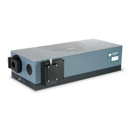
This User Guide covers the following models: Shamrock 500i (below left) Shamrock 750 (below right) The Shamrock 500i and 750 are available in two configurations: As a pre-aligned detector/spectrometer system allowing fast and efficient set-up, or, As a stand-alone spectrograph, to retrofit to existing cameras/systems Your Shamrock comes with a range of features including: •... -
Page 11: Technical Support
Shamrock 500i & 750 1.1 t echnical upport If you have any questions regarding the use of this equipment, please contact the representative* from whom your system was purchased, or: Europe Andor Technology Ltd. Andor Technology 7 Millennium Way 425 Sullivan Avenue... -
Page 12: Disclaimer
The copyright in this document and the associated drawings are the property of Andor Technology Ltd. and all rights are reserved. This document and the associated drawings are issued on condition that they are not copied, reprinted or reproduced, nor their contents disclosed. -
Page 13: 1.5 Packing List
Shamrock 500i & 750 1.5 packing liSt After having removed the spectrograph from its packaging, confirm that the following standard items are included: Item Quantity Shamrock Spectrograph Model 500i or 750 Description Quantity Description Quantity System Power Supply performance Unit (PSU) -
Page 14: Optional Accessories
Shamrock 500i & 750 1.5.1 o ptional cceSSorieS Depending on the Shamrock model and options purchased, the following optional accessories may also be included: • Detector flange(s) for output port(s). • Grating turret(s): The main grating turret may already be installed in the spectrograph. -
Page 15: Section 2: Product Overview
2.1.1 S hamrock The main external features of the Shamrock 500i are shown below. Features will vary depending on model type (see table). Removable top panel for access to interior e.g. Grating turret Side Output Port... -
Page 16: Shamrock 750
Shamrock 500i & 750 2.1.2 S hamrock The main external features of the Shamrock 750 are shown below. Features will vary depending on model type (see table). Removable top panel for access to interior e.g. Grating turret Exit Port 2... -
Page 17: Signal And Power Connections (500I And 750 Models)
Shamrock 500i & 750 2.2 S (500 ignal and ower onnectionS i and modelS 2.2.1 f ront anel The connections on the front panel of the Shamrock series are shown below: External Shutter I/O Connection Filter (15 pin) (9 pin) -
Page 18: Rear Panel
Shamrock 500i & 750 2.2.2 r anel The connections on the rear panel of the Shamrock 500i and 750 are shown below: Power Power Fuse Switch Input Holder Figure 4: Rear Panel Connections Power Switch Turn power off or on to the spectrograph. -
Page 19: Power Supply
Shamrock 500i & 750 2.3 p ower upply The Shamrock series are powered by external PSUs- details for each model are shown in the table below. Parameter 500i Mains Power Supply 100 - 240 V AC, 47 - 63 Hz... -
Page 20: Section 3: Installation
Shamrock 500i & 750 SECTION 3: INSTALLATION 3.1 a verview for etting up your hamrock pectrograph After you have removed the spectrograph from the box and checked all components against the packing list and they are as ordered, please follow the instruction below to prepare your spectrograph for use. An overview of the main steps is shown below: Installing the software (Solis for Spectroscopy or SDK). -
Page 21: Removing The Flipper Mirror Locking Screws
If your Shamrock 500 has a dual input option, there are locking screws located as shown in the following figures: Flipper mirror locking screw Figure 5: Location of the Shipping Screws (Shamrock 500i, Dual input Model) (1) If your Shamrock 500 has a dual output option, there is a screw located as shown below: Flipper mirror locking... - Page 22 Shamrock 500i & 750 750 Model The flipper mirror locking screws are located on the underside of the unit. It is therefore be necessary to carefully tilt or lift the Shamrock to allow access. Remember that the Shamrock spectrographs are heavy. Please observe precautions for safe movement and lifting as outlined in the preface of this manual.
-
Page 23: Installing The Software (Solis Spectroscopy/Sdk)
Shamrock 500i & 750 3.1.2 i /Sdk) nStalling the oftware oliS pectroScopy These guidelines provide a general overview; please refer to the software installation information supplied with your software. Terminate and exit any programmes which are running on the PC. -
Page 24: Software And Driver Installation
Shamrock 500i & 750 3.1.3 S oftware and river nStallation When the Andor Solis software is installed, the drivers for the Shamrock should be in the Shamrock USB Drivers folder. This is shown in the example below: NOTE: If the drivers are not present, copy the Shamrock USB Drivers folder from the installation CD-ROM to the Andor Solis folder. -
Page 25: Connecting The Power And Usb Cables
Shamrock 500i & 750 3.1.4 c uSb c onnecting the ower and ableS Ensure the power to the spectrograph is turned off and ensure that the switch on the rear of the spectrograph to set to OFF (0). Connect the power cable to the power supply input on the rear panel of the spectrograph. -
Page 26: Attaching A Camera To The Shamrock
Shamrock 500i & 750 3.2 a ttaching a amera to the hamrock If the spectrograph is not supplied with a camera/detector attached, refer to the guidelines below and also the user or installation guide(s) provided with your camera/detector. Remove the blanking plate from the spectrograph. -
Page 27: Usb Camera Signal And Power Connections
Shamrock 500i & 750 3.2.1 uSb c amera ignal and ower onnectionS The images below provide an overview of connection of a “USB” camera in this example an Andor iDus, to a Shamrock spectrograph. Camera and power connections will vary with your specific model of camera- refer to your camera user manual for additional information. -
Page 28: Standalone Spectrograph
Shamrock 500i & 750 3.2.2 S tandalone pectrograph Where a “standalone” spectrograph (i.e. without an Andor camera) has been purchased, the unit is supplied with an appropriate camera flange to allow a camera to be attached to the spectrograph body. The camera must be attached to the flange and the flange attached to the spectrograph body with the screws supplied. -
Page 29: Pre-Aligned Camera And Spectrograph
Shamrock 500i & 750 3.2.3 p aligned amera and pectrograph When a pre-aligned camera and spectrograph package has been purchased the camera comes pre-fitted with a flange. This flange accurately locates the camera and flange assembly to the spectrograph body via precision pins and matching bushings (see figure below). -
Page 30: Installation Of Filters (If Applicable)
Shamrock 500i & 750 3.3 i nStallation of ilterS if applicable Filters may be added, removed or replaced in the filter wheel via the filter access hole on the front face of the filter wheel housing. If this is necessary, please refer to the following procedures: 3.3.1 f... -
Page 31: Initializing The Filter Wheel
Shamrock 500i & 750 3.3.2 i nitializing the ilter heel After fitting, or replacing filters, it is good practice to synchronise the filter wheel hardware with the software interface. To re-initialise the filter wheel, press the reset button on the filter wheel control graphic. -
Page 32: Grating Turret Replacement
Shamrock 500i & 750 3.4 g rating urret eplacement The grating turret contained within the Shamrock spectrographs can be easily replaced by end-users. The procedure for replacing the Grating turret is outlined below: WARNINGS: • ENSURE THE SPECTROGRAPH IS SWITCHED OFF BEFORE REMOVING THE LID •... -
Page 33: Installation Of Accessory Parts
Shamrock 500i & 750 11. Now enter the grating and blaze values for the new turret as shown below. Entering the new turret values • Enter values for: - No of gratings - Grating lines/mm - Grating blaze (nm) • Grating Start should be left with the default values. -
Page 34: Grating Adjustment
Shamrock 500i & 750 3.5.1 g rating djuStment Grating fine adjustment may become necessary after your Shamrock has been shipped, or otherwise moved. Whilst every effort is made to limit the shifting of optical components during shipment, it is possible that some misalignment may occur. -
Page 35: Correcting For Roll And Tilt
Shamrock 500i & 750 3.5.1.2 c orrecting for oll and Screws are used for Roll and Tilt correction adjustment as shown below: There are two pairs of adjustment screws for Roll, and for Tilt (shown above). Each pair of screws work in opposition to each other, therefore for adjustment one should be loosened, then the other tightened. -
Page 36: Section 4: Operation
Shamrock 500i & 750 SECTION 4: OPERATION The Shamrock is controlled via the Dashboard control. This easy-to-use graphical user interface allows you to control the main hardware components of the Shamrock as well as several acquisition parameters. This can be seen in the figure below. -
Page 37: Emergency Mains Disconnection
Shamrock 500i & 750 4.1 e mergency ainS iSconnection In case of emergency, the disconnecting point of the equipment is the mains power cord connected to the external power supply, or the mains socket switch: FOR EMERGENCY MAINS DISCONNECTION, SWITCH OFF THE POWER AT THE MAINS SOCKET AND REMOVE THE MAINS LEAD FROM THE EXTERNAL POWER SUPPLY. -
Page 38: Read Mode Control
Shamrock 500i & 750 4.2.2 r ontrol The Read Mode Control dialog box can be used to change the way in which the information from the CCD in the camera is read. The mode is selected by clicking one of the buttons in the dialog box. Moving the cursor over each button displays a pop-up, indicating the mode selected by clicking on the button. -
Page 39: Spectrograph Controls
Shamrock 500i & 750 4.3 S pectrograph ontrolS 4.3.1 r eSet ptionS When the Reset button on the Reset Menu is clicked, you then have several options that allow you to reset the various mechanisms in the system. This may be found to be necessary if a mechanism setting appears to have deviated from the displayed value (e.g. -
Page 40: Wavelength Drive Control
Shamrock 500i & 750 4.3.2 w avelength rive ontrol The wavelength drive hardware sets the system to the target wavelength and also allows control of the grating selection. The wavelength range covered by the camera is calculated and displayed in the Wavelength section of the Dashboard. -
Page 41: Step And Glue
Shamrock 500i & 750 4.3.3 S tep and The step and glue function allows to user to build up a composite spectrum made up of individual spectra. The user selects the start and end wavelengths of the scan region and the grating to be used. The software will then control the acquisition of several spectra that cover this spectral region. - Page 42 Shamrock 500i & 750 Notice that the Step and Glue slide bar control will expand or contract in length to indicate the number of scans that the system must perform to acquire this data (see below). Note also that the acquire spectra overlap slightly. This allows the Step and Glue algorithm to glue the spectra together.
- Page 43 Shamrock 500i & 750 An Hg/Ne spectrum acquired with a 1200l/mm grating over the range 300 to 900nm (approx.) is shown below- It is composed of 13 individual spectra. Version 2.1 rev 13 Feb 2017...
-
Page 44: Relative Efficiency Correction
Shamrock 500i & 750 4.3.3.1 r elative fficiency orrection A Relative Efficiency Correction [REC] is possible in Step and Glue mode of your Andor Shamrock. This enables the quantitative measurement of peak intensity ratios, and to correct artefacts such as etaloning. -
Page 45: Grating Turret Control
Shamrock 500i & 750 4.4 g rating urret ontrol The Grating Turret Control is used to select a new grating by rotating the grating turret to a new position. There are three turret positions available so that a maximum of three grating can be fitted at any one time. If additional gratings are needed then the turret can be changed to install three new gratings. -
Page 46: Offset Adjustment Control
Shamrock 500i & 750 4.5 o ffSet djuStment ontrol The Offset Adjustment Control allows the user to adjust the calibration of the instrument. We shall define two types of offset. A detector offset and a grating offset. The Detector offset value can be adjusted to correct for any mechanical change that shifts (offsets) the displayed spectrum from the expected calibrated position. -
Page 47: Manual Grating Offset Adjustment Procedure
Shamrock 500i & 750 4.5.1 m anual rating ffSet djuStment rocedure Manual adjustment of detector or grating offset is selected via the tabs on the Offset Adjustment Control. The following describes the procedure for the detector offset adjustment but the grating offset adjustments are performed in the same manner. -
Page 48: Slit Drive Control
Shamrock 500i & 750 4.6 S rive ontrol The Slit Drive Control is used to control the Motorised Slit Assembly. The slits are used to control the amount of incident light that enters the spectrograph. The width can be varied between 10μm and 2500μm (in steps of 2.5μm). The slit height may be altered by interchanging optional baffle plates (attached to the slit assembly using 5x M2 cross-head screws). -
Page 49: Filter Wheel Control
Shamrock 500i & 750 4.7 f ilter heel ontrol The optional filter wheel accessory is controlled through the Filter Wheel Control: The Filter Wheel Control indicates the currently selected filter and provides details of the filter at the bottom of the control. -
Page 50: Shutter Control
Shamrock 500i & 750 4.8 S hutter ontrol If you have a shutter attached to your system the Shutter Control can be used to set the shutter mode of operation. There are a number of modes of operation available including:... -
Page 51: Control Of Shutter Via External Ttl Signal
Shamrock 500i & 750 4.8.1 c ttl S ontrol of hutter via xternal ignal For flexibility, the shutter in Shamrock spectrographs may also be operated by an external TTL signal. This allows the shutter to be operated by, and synchronised to, other laboratory equipment e.g. an Andor camera. The shutter connector is a standard female BNC type and is located at the front of the spectrograph below the flange mount. -
Page 52: Flipper Mirror Control
Shamrock 500i & 750 4.9 f lipper irror ontrol The Flipper Mirror Control allows you to rapidly select the required input or output port. The port is selected by simply clicking on the appropriate port on the Flipper Mirror Control dialog. The selected port is highlighted in yellow. -
Page 53: Dispersion Optimiser
Shamrock 500i & 750 4.10 d iSperSion ptimiSer The Dispersion Optimiser enables the dispersion on Andor Shamrock spectrographs to be fine tuned. Optimised dispersion will ensure that the calibration of wavelengths falling on the sides of the spectrum/sensor is accurate. -
Page 54: How To Use The Dispersion Optimiser
Shamrock 500i & 750 4.10.1 h ow to uSe the iSperSion ptimiSer Choose a Grating and Wavelength and Add them to the list. • Choose 1 grating, or the All Gratings Option. • Choose the wavelength you want to use. - Page 55 Shamrock 500i & 750 Click the Optimise button. • If you have Peak Checking enabled the following dialog will pop up at each of your chosen wavelength points to confirm the correct peak is being displayed. • Two red lines will be drawn around the center range being used and the user should confirm that the peak they are expecting is within this range.
- Page 56 Shamrock 500i & 750 • Once the operation is complete the following display will be added to the dialog. • The Current column shows the Optical Parameters currently in use, and the New column shows the recommended values calculated by the Optimiser.
-
Page 57: Section 5: Maintenance
Shamrock 500i & 750 SECTION 5: MAINTENANCE WARNINGS • THERE ARE NO USER-SERVICEABLE PARTS INSIDE THE SHAMROCK. • A NUMBER OF SCREWS ON THE SHAMROCK HAVE BEEN MARKED WITH RED ANTI-TAMPER PAINT. IF THESE ARE REMOVED, YOUR WARRANTY WILL BE VOID. -
Page 58: Section 6: Troubleshooting
Shamrock 500i & 750 SECTION 6: TROUBLESHOOTING Spectrograph does not switch on • Check that the power cord is plugged in and is connected correctly to mains supply • If the unit still does not switch on, check the correct fuse is properly installed and does not appear to be blown. -
Page 59: Section 7: Specifications
Shamrock 500i & 750 SECTION 7: SPECIFICATIONS 7.1 SpecificationS (electrical environmental) Parameter 500i Power supply ratings 100 - 240V, 50 - 60Hz, 2.5A Fuse rating 5A/500V EN 61010 Electrical safety USB 2.0 Communication Location to be used Indoor use only... -
Page 60: Specifications (Optical)
Shamrock 500i & 750 7.2 SpecificationS (optical) Unless otherwise stated, specifications are obtained using 1200l/mm gratings and 10 μm slits @ 500 nm central wavelength and Newton DU940 camera with 13.5 µm pixel and 26.7 mm wide array: Parameter 500i... -
Page 61: Appendix A: Mechanical Drawings
Shamrock 500i & 750 APPENDIX A: MECHANICAL DRAWINGS Dimensions in mm [inches] (Note SIde output port applies to “B” models only) Shamrock 500i Version 2.1 rev 13 Feb 2017... - Page 62 Shamrock 500i & 750 Screw Type Requirements • CCD flange to spectrograph flange 4 off, M4 x 16 • Camera to CCD flange 4 off, M3 x 10 • iXon camera to iXon flange 4 off, M5 x 10, countersunk, hex head...
- Page 63 Shamrock 500i & 750 Shamrock 750 Version 2.1 rev 13 Feb 2017...
- Page 64 Shamrock 500i & 750 Screw Type Requirements • CCD flange to spectrograph flange 4 off, M4 x 16 • Camera to CCD flange 4 off, M3 x 10 • iXon camera to iXon flange 4 off, M5 x 10, countersunk, hex head...
-
Page 65: Appendix B: Other Information
Shamrock 500i & 750 APPENDIX B: OTHER INFORMATION erms and ondiTions of ale and arranTy nformaTion The terms and conditions of sale, including warranty conditions, will have been made available during the ordering process. The current version may be viewed at: www.andor.com/pdfs/literature/Andor_Standard_Warranty.pdf...
Need help?
Do you have a question about the Shamrock 500i and is the answer not in the manual?
Questions and answers