Table of Contents
Advertisement
Quick Links
MV33 Installation Guide
Overview
The Cisco Meraki MV33 series are network cameras that are exceptionally simple to deploy and configure due to their integration into the Meraki Dashboard and
cloud-augmented edge storage. The MV family eliminates complex and costly servers and video recorders required by traditional solutions, removing the
limitations typically placed on video surveillance deployments.
Package Contents:
In addition to the MV camera, the following are provided:
Unit
Mounting Equipment
MV33-HW
1 x base mount plate small
1
Advertisement
Table of Contents

Subscribe to Our Youtube Channel
Related Manuals for Cisco MERAKI MV33

Summary of Contents for Cisco MERAKI MV33
- Page 1 Overview The Cisco Meraki MV33 series are network cameras that are exceptionally simple to deploy and configure due to their integration into the Meraki Dashboard and cloud-augmented edge storage. The MV family eliminates complex and costly servers and video recorders required by traditional solutions, removing the limitations typically placed on video surveillance deployments.
- Page 2 Powering the MV33 Series The MV33 features a 1000BASE-TX Ethernet port and requires 802.3af PoE minimally for operation. Route the Ethernet cable from an active PoE switch or injector port on a PoE switch or injector.
- Page 3 *.devices.meraki.direct and that these domain requests are forwarded to Google public DNS. Assigning IP Addresses Currently, the MV33 series camera does not support static IP assignment. MV33 units must be added to a subnet with DHCP and available DHCP addresses to operate correctly.
- Page 4 Note: If the microphone switch is disabled and the camera is mounted, toggling the switch back ON would require accessing the camera's base. The MV33 also features a Factory Reset button which lies right under the microphone cut-off switch. This reset function can be activated by inserting a reset pin into this section for 15 seconds.
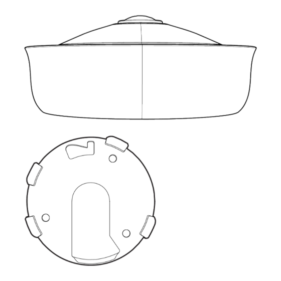
- Page 5 • Use 3x Wall anchor and screws to fix the base plate to the wall. • The MV33 Series cameras have a button to engage the locking mechanism. Press the button while aligning the camera to the small base plate.
- Page 6 •...
- Page 7 • Twist the camera while holding the button until a click is heard. • The camera is locked onto the plate and secured. • Remove the protective cover. • Observe the status LED on the top of the camera lens assembly and ensure the camera is connected via Ethernet (solid green) or WiFi (solid blue). An MV must first be provisioned over a wired Ethernet connection before it can be deployed wirelessly.
- Page 8 MV33 LED Status Indicator Your MV33 series is equipped with an LED light on the front of the unit to convey system functionality and performance information. The following colours and patterns indicate the various status conditions of an MV: •...
Need help?
Do you have a question about the MV33 and is the answer not in the manual?
Questions and answers