Table of Contents
Advertisement
Quick Links
Advertisement
Table of Contents

Related Manuals for TigerStop SawGear Touch


Summary of Contents for TigerStop SawGear Touch
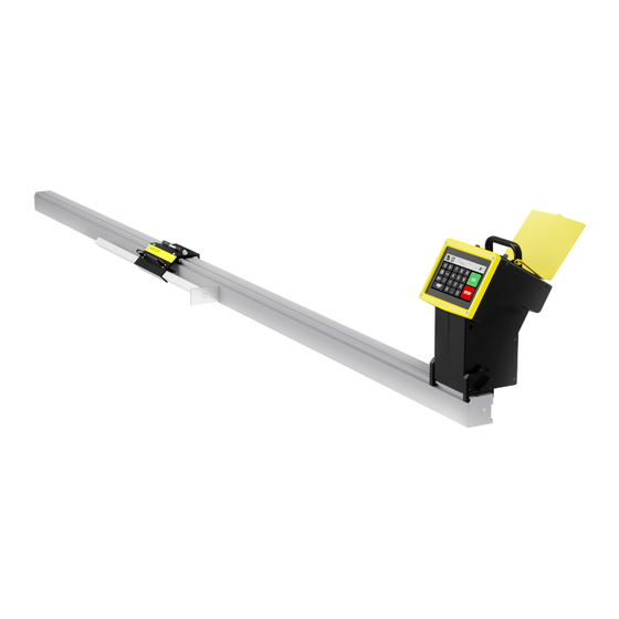
- Page 1 SawGear Touch™ User Manual...
-
Page 3: Table Of Contents
PTimized anual ovemenT 33 SawGear Touch Crown & 20 SawGear Touch Navigating Miter Pro Menus 36 SawGear Touch Framing creen 38 Maintenance Schedule & m aviGaTinG eTuP enuS... - Page 4 GENERAL WARNINGS WARNING: Installation of your TigerStop® Product must be done by a person trained in the safe design and installation of automation products, and in the safe operation of power equipment. Ensure that such installation meets all legally required safety requirements and guidelines, and that proper guarding and safety devices are provided on all sides of the equipment to preclude unintended access during operation.
- Page 5 Don’t get pinched by the push feeder. Keep your hands away when in motion! Keep the work area clean and well lighted to avoid accidental injury. Do not use TigerStop® machines in a dangerous environment. Using power tools in damp or wet locations or in rain can cause shock or electrocution.
- Page 6 Customer Service will email you the enable code during business hours, Monday-Friday 6am- ® 4pm PST. You can also request the code by phone. 3. After installing SawGear Touch, power it on and follow the '1st Power-On' (page 15) instructions.
-
Page 7: Contact Us
+1 (360) 260 0755 TigerStop Europe TigerStop Europe Email: info@tigerstop.nl Phone: +31 546 575 171 TigerStop Europe | Sales TigerStop Europe | Sales Email: info@tigerstop.nl Phone: +31 546 575 171 (option 2) TigerStop Europe | Service TigerStop Europe | Service Email: sos@tigerstop.nl... -
Page 8: Parts Inventory
Parts Inventory Power Head Touch DESCRIPTION PART QUANTITY (NUMBER) Power Head Touch (SA2521) Power Cable (PC) Saw Gear Beam DESCRIPTION PART QUANTITY (NUMBER) Saw Gear Beam (SGXX) Flip-Away Stop Assembly DESCRIPTION PART QUANTITY (NUMBER) Flip-Away Stop (SA2545) M6 Adjustable Handle (F7306) -
Page 9: Ench M Ount A Ssembly
Parts Inventory Stops DESCRIPTION PART QUANTITY (NUMBER) Stop Bar (SA2555) Crown Moulding Foot (Optional) (SG-CMF) Bench Mount Assembly DESCRIPTION PART QUANTITY (NUMBER) Bench Mount Bracket (M1016) M8 Star Knob (F7304) Bench Mount Hardware Pack (F0038) - Page 10 Parts Inventory Table Assembly (Optional) DESCRIPTION PART QUANTITY (NUMBER) SawGear Table Varies (SGTABXX) Tool Bracket 2 per table (M1035) Saw Bracket Left/Right 1 per table (M1042/3) Table Spacer 2 per table (M1041) M6x16mm Carriage Bolt 4 per table (F0183) M6 Washer 4 per table (F7620) M6 Hex Nut...
- Page 11 Parts Inventory DESCRIPTION PART QUANTITY (NUMBER) M8x35mm T-Bolt 3 per table (F0184) M8 Positioning Pin 2 per table (M1044) M8x8mm Set Screw 2 per table (F9811) M8 Weld Nut 2 per table (F0406) Table Leg Varies (SB2120) M10 Washer 2 per table (F3009) M6x10mm Button Flange Cap Screw...
-
Page 12: Sawgear Touch Installation
VOLTS CIRCUIT BREAKER 120V 208/230/240V 20A (USA)/16A (EU) SawGear Touch requires a dedicated, grounded circuit. Operating SawGear Touch without proper grounding risks electrocution. SawGear Table Installation T Tac h o o l r ac keTS Included Place a Tool Bracket under both corners on one side of the tool. - Page 13 SawGear Touch Installation 2. Place a Table Spacer between each Tool Bracket and the tool. 3. Fasten the tool, Table Spacers, and Tool Brackets together. T Tac h r ac keT Place the Saw Bracket between the Tool 2. Fasten the Saw and Tool Brackets together with Brackets and the tool.
- Page 14 SawGear Touch Installation T Tac h ab le To r ac keT Insert an M8 Weld Nut into the middle track and fasten it with an M8x8mm Set Screw about 12” (305mm) from the tool end of the table. 2. Insert an M8 T-bolt into each track on the tool end of the table.
- Page 15 SawGear Touch Installation nsert the Positioning Pins through the top of the Saw Bracket and slide the table to make it flush with the tool. Tighten the Positioning Pins. 6. Slide the Knob into the Saw Bracket’s top slot and fasten the table to the bracket.
- Page 16 SawGear Touch Installation ress in the metal buttons on the legs to adjust the table height. Make it level. 3. Secure the legs with the orange handles. SawGear Bench Mount Brackets ec u r e e ar i n Th e b r ac keTS Make sure both Bench Mount Brackets are approximately in line.
- Page 17 SawGear Touch Installation 2. Lay the SawGear Beam across the Bench Mount Brackets. 3. There is an angled channel running along the full length of the Beam’s bottom; pivot the Beam so the curled front edge of the Bench Mount Brackets fit into this channel.
- Page 18 SawGear Touch Installation Connecting the Flip-Away Stop Remove the rod from the Flip-Away Stop. 2. Insert the Adjustable Handles and tighten with their supplied hardware. 3. Align the cylinders of the Flip-Away Stop and SawGear carriage and insert the rod’s washers between them.
- Page 19 SawGear Touch Installation Connecting the Power Head Touch nsert the Power Head Touch into either of the SawGear Touch Beam’s attachment points. Ensure it is rotated slightly counter-clockwise when inserting. 2. Rotate into place, clockwise. 3. Turn the knobs on both sides to secure the Power Head Touch to the Beam.
- Page 20 SawGear Touch Installation Checking Pivot Range of Movement Pivot the saw to its furthest left and right positions. If the table blocks the saw’s pivot, trim the corner of the SawGear table to accommodate the saw. If the Power Head Touch blocks the saw’s pivot, either move the Power Head Touch to the other end of the beam or scoot the beam away from the saw until the saw can move through its full range-of-motion.
-
Page 21: Sawgear Touch Setup
4. Enter the Enable Code and then press Or download an Enable Code: Insert a USB with a valid Enable Code. Press • SawGear Touch proceeds automatically. 5. Choose if the SawGear Touch is on the left or right side of the tool and then press... - Page 22 SawGear Touch Setup 6. Choose Inches or Millimeters and then press Press to run the Home Routine and then press 8. Press to run the MinMax Routine and then press 9. Initial Calibration a. Press to go to the home screen.
-
Page 23: Sawgear Touch Operation
SawGear Touch Operation SawGear Touch Home Screen Miter: Enables miter movement. Home: Returns to the Home screen. Current field: Displays the current position. Menu: Opens the Menu screen. Next field: Displays the next position. Unit Toggle: Switches between inches and millimeters. - Page 24 • Wait a few seconds for power up. 2. Press to run the Home Routine. • SawGear Touch is ready to work. Manual Movement aS i c ove m e nT Executes simple movements. Use the Number Keypad to enter a length into the 'NEXT' field.
- Page 25 4. Press and enter the stock width. Then press again. 5. Enter the desired back length into the 'NEXT' field. 6. Press • SawGear Touch moves to a compensated position. Press to return to basic movement.
-
Page 26: Sawgear Touch Navigating Menus
Setup: View and modify important settings. Crown & Miter Pro: Automatically determines cutting angles and Stop positions for baseboard and crown molding. My SawGear: View and update SawGear Touch’s software and firmware. Framing: Automatically determines cutting angles and Stop positions for framing. -
Page 27: Sawgear Touch Setup Menu
See Appendix A (page 40) for instructions on calculating a new Scale value. Units Select whether SawGear Touch works in inches or millimeters. Calibration Proper calibration is essential for maintaining accuracy. Move the Stop to a position between 2"- 5" (50mm- 125mm). -
Page 28: Ome R Outine
Stop’s path. • Press to run the routine. Press to halt. Orientation Select if the SawGear Touch is on the left or right side of the saw. Determines which way the Stop moves. After changing orientation, perform the following: •... -
Page 29: Rinting
(page 43). Increment Sets the distance the Stop moves with each press of Kerf Sets the width of the saw blade. SawGear Touch accounts for this width when moving the Stop. Measure and update Kerf with every saw blade change. -
Page 30: Isible
SawGear Touch Setup Menu CSV Length Column For downloaded part lists, only. Sets from which column SawGear Touch pulls part length information. CSV Quantity Column For downloaded part lists, only. Sets from which column SawGear Touch pulls part quantity information. - Page 31 Load the stock. For safety, use 2” (51 mm) wide or thinner stock. 2. Make a 90°/0° head cut. 3. Rotate the saw 45° towards the SawGear Touch. 4. Press 5. Cut the stock. 6. Measure the back length of the part. Use calipers, if possible.
-
Page 32: Sawgear Touch My Sawgear Menu
Please contact TigerStop Customer Service ® to enable additional features. Interface Version View SawGear Touch’s interface version and update it, if needed. Insert a USB with interface update files. 2. Press • Wait for SawGear Touch to download the new interface version. - Page 33 SawGear Touch My SawGear Menu Firmware Version View SawGear Touch’s firmware version and update it, if needed. Insert a USB with firmware update files. 2. Press • Wait for SawGear Touch to download the new firmware version. 3. Press Debug Mode...
-
Page 34: Sawgear Touch Lists
SawGear Touch Lists Download a List Insert a USB with compatible .CSV files. 2. Press • SawGear Touch takes the lists from the USB and puts them into the File Name column. Make a List Press 2. Press to make an entry. - Page 35 SawGear Touch Lists 3. Press the Length box and enter a length. 4. Press the Quantity box and enter a quantity. 5. Press to save the entry. 6. Press to return to the list. Return to step 2 to make additional entries.
- Page 36 SawGear Touch Lists 2. Select an entry from the list. 3. Either: a. Press the Length box to edit the length. b. Press the Quantity box to edit the quantity. c. Press to save the entry. d. Press to return to the list 4.
- Page 37 6. Return to step 3. • To edit the part list without exiting, press to pause. Press to resume. • To exit the part list, press SawGear Touch does not save part list progress when exiting.
- Page 38 6. Remove the part and stock. Press • SawGear Touch selects the next part length that makes the most of the stock. • If no part lengths fit in the remainder of the stock, return to step 3. 8. Return to step 5.
-
Page 39: Sawgear Touch Crown
SawGear Touch Crown & Miter Pro Press the ‘Width’ field and enter the width of the stock. 2. Select Crown or Baseboard. 3. Select a left or right side starting cut. 4. Select an Inner or Outer Corner cut. 5. Enter the angle of the corner. - Page 40 SawGear Touch Crown & Miter Pro 9. Select Inner or Outer Corner for the second cut. 10. Enter the angle of the second corner. 11. Press 12. Rotate the saw to the displayed angle. 13. Press 14. Make the angled head cut. Flip away the Stop, if necessary.
- Page 41 SawGear Touch Crown & Miter Pro 16. Rotate the saw to the displayed angle. 17. Press to move to the compensated position. 18. Butt the stock against the Stop. 19. Make the second cut to finish the piece. 20. Press to return to the “Select Starting Edge”...
-
Page 42: Sawgear Touch Framing
Frame width. • Corner angle. • Rabbet depth. 2. Press 3. Rotate the saw towards SawGear Touch. Match the Tool Angle on display. 4. Press 5. Make the angled head cut. 6. Press Rotate the saw away from SawGear Touch. Match the Tool Angle on display. - Page 43 SawGear Touch Framing 10. Cycle the saw to finish the part. 11. Press to return to the “Enter Frame Info” screen. • Repeat from step 1 for additional pieces.
-
Page 44: Maintenance Schedule
Maintenance Schedule eco r d m p o rTanT eT Ti n G S Setting Value Setting Value Serial # Scale Min Limit Kerf Max Limit ai ly • Clean all dirt and debris from drive areas. • Check all cables for damage. o nTh ly •... -
Page 45: Maintenance Log
Maintenance Log Date Maintenance Performed Notes... -
Page 46: Appendix A: Scale
Appendix A: Scale Scale requires adjusting when the accuracy of the Stop’s movement gets worse as it moves from the calibration point, only. Always perform calibration BEFORE adjusting scale. Scale is the setting that correlates motor rotation to the distance traveled. The fastest way to arrive at the correct scale is through the scaling cycle. -
Page 47: Appendix B: Printer Kit
Appendix B: Printer Kit Printer Kit Parts DESCRIPTION PART QUANTITY (NUMBER) Printer Package (LP2844) USB Cable (J8030) Printer Stand Cover (M0025) Printer Stand Base (M0024) Square Tube (M1808) Round Tube (M1807) Printer Stand Base Half-Bracket (M10070) M6x14mm Socket-Head Screw (F7216) - Page 48 Follow the included Printer Quick Start Guide to learn how to load labels and configure the printer. • Use 2” labels, only. 2. Connect the Power Head Touch and the Printer via USB Cable. 3. Enable printing on the SawGear Touch (page 23). 4. Run a part list (page 31) and the Printer automatically produces labels with part length and quantity.
- Page 49 Appendix B: Printer Kit Printer Stand Assembly The printer stand mounts the printer to any support structure. The printer stand pivots between 0-90° with the base hardware. 1. Place the Printer Stand Base Brackets against the Round Tube and insert two M8x45mm Hex-Head Screws through all three parts.
- Page 50 Appendix B: Printer Kit 5. Place the Spacer between the Square Tube’s holes. 6. Connect the Spacer, Printer Stand Base, and Tube with an M8x50mm Hex-Head Screw. 7. Fasten with an M8 Flange Nut. 8. Place the Printer onto the Printer Stand Base, facing forwards. 9.
- Page 52 TigerStop Product COMPARISON CHART Power Working Max Load Product Drive Type Accuracy Requirement Length Push 2 AA +/- .008” 0’ - 20’ Caliper TigerSPC +/- 0.2mm 0m - 6m Battery 32mm Belt +/- .008” 8’ - 20’ SawGear Stop Only 110 Vac +/- 0.2mm...
Need help?
Do you have a question about the SawGear Touch and is the answer not in the manual?
Questions and answers