Table of Contents
Advertisement
Quick Links
Advertisement
Table of Contents

Related Manuals for CYBEX 13250-999-4 AC


Summary of Contents for CYBEX 13250-999-4 AC
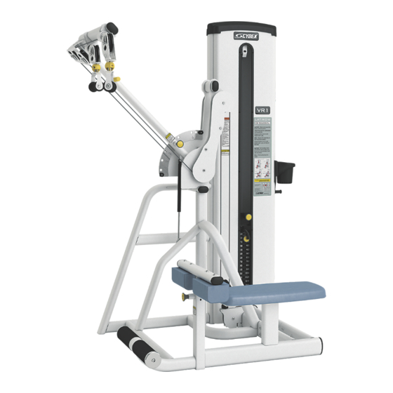
- Page 1 ® Lat/Row Owner's Manual Part Number 13250-999-4 AC...
-
Page 3: Table Of Contents
Cybex International, Inc. DISCLAIMER: Cybex International, Inc. makes no representations or warranties regarding the contents of this manual. We reserve the right to revise this document at any time or to make changes to the product described within it without notice or obligation to notify any person of such revisions or changes. -
Page 4: Safety Guidelines And Practices
• Fasteners must have a minimum of 500 lbs. tensile capacity. Cybex recommends .3/8” grade 2 bolts or better. A minimum pull force of 220 lbs/100 kgs is required for each anchor position. -
Page 5: User Safety Precautions
• DO NOT pin weights on selectorized equipment in an elevated position or use the machine if found in this position • DO NOT increase weight resistance on equipment by any means other than those provided by Cybex. • DO NOT wear loose or dangling clothing or jewelry while using equipment. Stay clear of moving parts. -
Page 6: Label Placement
Label Placement The following diagram shows where each label is located. Page 6 of 25... - Page 7 Description DE000001-X DE000005-X 4510-321-X 8500-025-X Page 7 of 25...
-
Page 8: Assembly
Assembly Machine Specifications Total Weight and Size VR1 Lat/Row 13250 Standard Stack Weight Machine Dimensions at Rest Machine Dimensions in Use 496 Lbs 73” L × 50” W × 83” H Same 225 Kg 185 cm L × 127 cm W × 211 cm H Same Total Weight and Size VR1 Lat/Row 13250 Standard Stack Weight... -
Page 9: Environment
All other machines must have a clear floor space of 23” for all access point on the machine, unless shown in the Owner’s Manual. Environment Humidity and Static Electricity The unit is designed to function normally in an environment with a relative humidity range of 30% to 75%. The unit can be shipped and stored in a relative humidity range of 10% to 90%. -
Page 10: Tools Required
• Fasteners must have a minimum of 500 lbs. tensile capacity. Cybex recommends .3/8” grade 2 bolts or better. A minimum pull force of 220 lbs/100 kgs is required for each anchor position. - Page 11 Verify proper operation If machine CANNOT be moved without adding or removing weight stack Two people will be required for this procedure 1. Remove the two Button Head Socket Cap Screws (BHSCS) securing the top cap to the frame using a 7/32” Allen wrench.
- Page 12 7. Remove spiral pin securing cable end to top weight using a 3/16” pin punch and hammer. Description Qty. Spiral pin Cable Top weight connector 8. Remove lifting post. 9. Remove weight plates. 10. Move to desired location. 11. Remove shipping cones using a 3/4” socket or wrench. Remove bolt from shipping cone with hammer.
- Page 13 Apply weight plate decal 1. Peel off half of backing from weight plate decals, making sure that the decals remain attached to the front sheet. Description Backing Front sheet Weight decals 2. Place decals front sheet in the correct position on weight plates. 3.
- Page 14 3. Pull cable tight and secure in place with spiral pin using a 3/16” pin punch and a hammer. Description Qty. Spiral pin Cable Top weight connector 4. Place weight stack selector pin in each plate to verify proper installation. 5.
- Page 15 • Fasteners must have a minimum of 500 lbs. tensile capacity. Cybex recommends .3/8” grade 2 bolts or better. A minimum pull force of 220 lbs/100 kgs is required for each anchor position.
-
Page 16: Exercise
Exercise Intended Use The intended commercial use of this machine is to aid exercise and improve general physical fitness. Instructions TIP: Read and understand all instructions and warnings prior to using this machine in the Safety section of the Owner’s Manual. CAUTION: Use only in manner depicted. - Page 17 Start/Finish Lat Pull Start/Finish Row Muscles Used Lat Pull - Latissimus Dorsi, Teres Major, Biceps, Middle Trapezius, Rear Deltoid, Rhomboid Row - Latissimus Dorsi, Teres Major, Biceps, Middle Trapezius, Rear Deltoid, Rhomboid Page 17 of 25...
-
Page 18: Maintenance
Cybex International, Inc. is not responsible for performing regular inspection and maintenance actions for your machines. Instruct all personnel in equipment inspection and maintenance actions and also in accident reporting and recording. Cybex International, Inc. representatives are available to answer any questions that you may have. Warnings TIP: Read all warnings in this chapter. -
Page 19: Weekly Procedures
Then Dampen a soft white cloth with rubbing alcohol. More Difficult Stains Gently rub stained area. (Alternative Method) Dampen a clean soft cloth in water and rinse area. Apply a light coat of furniture wax for 30 seconds. Restoring Luster Lightly rub area using a clean white cloth. -
Page 20: Yearly Procedures
• Hammer • 3/16” Pin punch Four types of cable tension adjustment are used on Cybex Strength Systems: Jam Nut Adjustment This type of adjustment uses a jam nut and a tension adjustment nut at the cable cam end as the primary adjustment. - Page 21 Description Qty. Jam nut Tension adjustment nut Rod End Adjustment This type of adjustment uses a socket head cap screw (SHCS) securing a cable rod end bearing to the machine. Primary adjustment is by turning the rod end bearing. The other end of the cable usually contains a roll pin cable adjustment.
- Page 22 Description Qty. Cam bolt adjustment Page 22 of 25...
-
Page 23: Customer Service
To speak with a customer service representative, call 800-351-3737 (for customers living within the USA) or 847-288-3700 (for customers outside the USA). The following information located on the serial number decal will assist our Cybex representatives in serving you. • Unit Serial Number, Product Name and Model Number •... -
Page 24: Damaged Parts
At Cybex’s discretion, the technician may request that you return the problem part(s) to Cybex for evaluation and repair or replacement. The technician will assign you a RMA number and will send you an ARS label. The ARS label and the RMA numbers must be clearly displayed on the outside of the package that contains the item(s) to be returned. - Page 26 Columbia Center III - 9525 West Bryn Mawr Ave, Rosemont, IL 60018 • 800-351-3737 • 847-288-3700 • FAX 800-216-8893 www.cybexintl.com...
Need help?
Do you have a question about the 13250-999-4 AC and is the answer not in the manual?
Questions and answers
How can fix this machine ?
To fix the CYBEX machine with part number 13250-999-4 AC, follow these steps:
1. Identify the Problem – Provide the model and serial number of your Cybex equipment and describe the issue.
2. Contact Cybex Support – A technician may request you return the problematic part(s) for evaluation, repair, or replacement.
3. Obtain an RMA Number – The technician will assign you an RMA number and send you an ARS label.
4. Package the Part(s) Properly – Clearly display the RMA number on the package and include a description of the problem, the serial number, and the owner’s name and address.
5. Return the Part(s) to Cybex – Ship the package according to the instructions. Note that shipments sent COD or without an RMA number will not be accepted.
6. Handle Shipping Damages – If the part was damaged in shipment, report it to the carrier immediately and follow their claim process.
If the issue is related to maintenance, inspect and replace any worn or damaged components, ensuring proper installation and anchoring of the machine.
This answer is automatically generated