Table of Contents
Advertisement
Reference use and maintenance manual
SPIDER 18.90 PRO
Attention
Before proceeding with any work on the machine read the present handbook in its entirety
and ensure you understand the information contained herein.
Keep the handbook in a safe place where it is easily accessible for consultation.
ORIGINAL INSTRUCTIONS
Aerial work platform
Code
Version
1
EN
4848520200
05/2012
Advertisement
Table of Contents

Related Manuals for PLATFORM BASKET SPIDER 18.90 PRO


Summary of Contents for PLATFORM BASKET SPIDER 18.90 PRO
- Page 1 Reference use and maintenance manual SPIDER 18.90 PRO Aerial work platform Attention Before proceeding with any work on the machine read the present handbook in its entirety and ensure you understand the information contained herein. Keep the handbook in a safe place where it is easily accessible for consultation.
- Page 2 Tel: +39 0522967666 Fax: +39 0522967667 www.platformbasket.com DOCUMENT TYPE: OWNER’S MANUAL MODEL: SPIDER 18.90 PRO SERIAL NUMBER: CUSTOMER: YEAR OF MANUFACTURE: The contents of the present document cannot be used, reproduced or transferred to third parties without the express permission of builder.
-
Page 3: Purpose Of The Manual
Any alteration and/or modifi cation to the machine is SE- VERELY PROHIBITED, without the prior authorization of Platform Basket. This “SAFETY SYMBOL” is used to call attention to potential dangers which may cause injury or death if they are underestimated. - Page 4 INDEX INTRODUCTION PURPOSE OF THE MANUAL INDEX CONSULTATION SECTION INSTRUCTIONS AND GENERAL SAFETY RULES INTRODUCTION MACHINE IDENTIFICATION GENERAL SAFETY RULES PREPARATION AND INSPECTION SIGNS AFFIXED TO THE MACHINE QUALIFICATION OF OPERATING PERSONNEL CUSTOMER’S RESPONSIBILITY AND MACHINE CONTROLS OPERATING POSITIONS THE ROLE OF THE OPERATORS...
- Page 5 INDEX SECTION DESCRIPTION AND USE OF THE MACHINE TECHNICAL INFORMATION GENERAL DESCRIPTION SAFETY DEVICES GROUND CONTROL PANEL ELECTRIC PUMP CONTROL PANEL CONTROLS FOR MOVEMENT/ STABILISATION GROUND CONTROL LEVERS (FOR THE AERIAL PARTS) CONTROL PANEL ON THE BASKET CONTROL LEVERS IN THE BASKET OTHER DEVICES TRANSPORT SWITCH ON / SWITCH OFF...
- Page 6 INDEX SECTION MAINTENANCE INTRODUCTION MAINTENANCE WORK SAFETY MAINTENANCE SCHEDULE GREASING AND LUBRICATION LUBRICANT TABLE SCREW TIGHTENING SUPPLIES CHECK OIL LEVEL / TOP UP / REPLACE TRACK REDUCTION GEAR OIL HYDRAULIC OIL LEVEL CHECK SLIDING BLOCK WEAR AND CHAINS CONTROL (WHERE THERE ARE)
- Page 7 INDEX SECTION REGISTER AND CONTROL COUPONS MAINTENANCE RECORDS AND LOGBOOK CHANGE OF OWNERSHIP RECORD MAINTENANCE RECORD SPARE PART REPLACEMENT RECORD MAINTENANCE RECORDS SECTION INTEGRATION FOR RADIO COMMAND VERSION SIGNS AFFIXED TO THE MACHINE GENERAL DESCRIPTION TRAVELLING / STABILISATION COMMANDS EMERGENCY MANOEUVRE SECTION INTEGRATION FOR CABLE COMMAND VERSION SIGNS AFFIXED TO THE MACHINE...
- Page 8 INDEX SECTION OPTION TEMPERATURE SENSOR BASKET WITH LOAD CELL HORN...
- Page 9 CONSULTATION BEWARE It is necessary to read and understand the manual before using the machine. The manual is subdivided into 8 sections INTRODUCTION OF THE HANDBOOK SAFETY INSTRUCTIONS AND RULES USER MANUAL MAINTENANCE LOGBOOK AND CONTROL COUPONS INTEGRATION FOR RADIO COMMAND VERSION INTEGRATION FOR CABLE COMMAND VERSION OPTIONAL...
- Page 10 SECTION INSTRUCTIONS AND GENERAL SAFETY RULES...
-
Page 11: Machine Identification
INTRODUCTION With this manual Platform Basket wishes to provide operators with the directions and information necessary for the correct use of the aerial platform and its routine maintenance for the purposes of ensuring the best performance and longest life of our product. -
Page 12: General Safety Rules
GENERAL SAFETY RULES Most of the accidents that occur at work are due to negligence in the maintenance or operation of the machine. It is therefore necessary to read this manual so as to be able to operate in the greatest possible safety and always maintain the machine in a state of ef! ciency. - Page 13 Do not push or pull the machine or other objects using the telescopic mechanism of the boom. Do not leave components on the railings of the basket without Platform Basket’s approval. Never use the boom other than for moving personnel, their tools and equipment to the work position.
- Page 14 GENERAL SAFETY RULES Never work with a machine in poor working condition. If there should be a break down, stop the machine, place a CLEARLY VISIBLE sign and advise the personnel in charge. Sudden or acrobatic movements must not be done on the basket. The operator is prohibited to move between the basket and a structure outside the machine, machine stability could be jeopardised.
-
Page 15: Preparation And Inspection
PREPARATION AND INSPECTION GENERAL PREPARATION This section provides the personnel responsible for making the machine ready and for its entry in operation with the information necessary and lists the checks that are to be done before operating the machine. It is important that the information given in this section is read and understood before using the machine. - Page 16 10 - Check that the tank and hydraulic pipes are not damaged or leaking and that the re! ll plug is locked in position. NOTE Platform Basket recommends that the hydraulic oil fi lter be replaced after the fi rst 50 hours of operation and every 300 hours thereafter, unless exceptional working conditions require more frequent replacement.
- Page 17 PREPARATION AND INSPECTION TURRET 1 - Check the turret for damage, loose or missing parts and that it is locked in position. Check that the rotation gears and its brake do not show signs of damage, loose or missing parts, that the hydraulic pipes and the component housings do not show signs of leaks;...
-
Page 18: Daily Visual Inspection
PREPARATION AND INSPECTION 5 - Check that the hydraulic directional control valve and its tubes are not leaking or damaged. NOTE Check that all the signs DANGER, WARNING, INSTRUCTION applied all over the machine are in position and legible. BOLT AND SCREW TIGHTENING The tightening torque table (see the pages speci! ed) consists of standard torque values, based on the diameter and the class (hardness) of the screws;... -
Page 19: General Inspection
PREPARATION AND INSPECTION NOTE Check visually and manually that the safety micro-switches are in position and that they are working cor- rectly. 6 - Check that the brakes work correctly when the machine is moving on a slope with gradient not exceeding the speci! cation in the technical data, and stop the machine. - Page 20 PREPARATION AND INSPECTION 11 - Fuel feed - Fuel tank cap should be locked in position; there should be no visible damage to the tank and no sign of leakage; correct level. 12 - Ground controls - Switches should be working; no damage visible; labels should be in place and legible. 13 - Hydraulic oil tank - The oil level should be correct (check the level when the oil is cold, the components are not moving and the machine is in the rest position);...
-
Page 21: Maintenance Of The Batteries
PREPARATION AND INSPECTION 2 - Raise, extend, retract and lower the booms. Check that the operation is normal and without obstructions. 3 - Extend the telescopic boom so that it moves from the retracted position to the extended position and vice versa a number of times with different lengths of extension. -
Page 22: Danger-Electrical Hazard
SIGNS AFFIXED TO THE MACHINE Hook up point for hoisting the machine. Hand pump. Max load 200 kg Topping up oil. DANGER-ELECTRICAL HAZARD CAUTION DANGER CAUTION WHEN DRIVING THIS MACHINE, ALWAYS REMAIN STANDING IN THE BASKET. OR, IF REMOTE CONTROLLED, ALWAYS ELECTRICAL HAZARD STAND AT LEAST 1 MTR AWAY FROM THE THIS MACHINE IS NOT INSULATED... - Page 23 SIGNS AFFIXED TO THE MACHINE General safety rules Compulsory safety wbelts. Read the use and maintenance manual.
- Page 24 SIGNS AFFIXED TO THE MACHINE Not walkable area. Tools - electric pump. 220 VAC label. Heat source.
- Page 25 SIGNS AFFIXED TO THE MACHINE Diverter valve. Emergency procedures. 1° - 2° - 3° - 860246 Battery switch. Max load upon one stabilizer.
-
Page 26: Qualification Of Operating Personnel
QUALIFICATION OF OPERATING PERSONNEL The personnel using or operating the machine must be competent and meet the following requirements: PHYSICAL Good eyesight, hearing, co-ordination and the ability to safely carry out all the necessary facilities required for use of the machine. MENTAL Ability to understand and apply the established safety standards, precautions and rules. -
Page 27: Personnel Training
CUSTOMER’S RESPONSIBILITY AND MACHINE CONTROLS GENERAL RESPONSIBILITIES Since the manufacturer of the machine cannot exert any direct control over the applications and operation of the machine, these activities are the exclusive responsibility of the user and co-workers. PERSONNEL TRAINING The lifting platform is a machine intended for use by personnel. As a result it is essential that its operation and maintenance are entrusted only to authorized personnel who have demonstrated that they understand how to use and maintain the machine. -
Page 28: Operating Positions
OPERATING POSITIONS The machine can be driven from the following stations: on the basket for one operator; on the turret and on the chassis as emergency station ! xed on the chassis for traslation and stabilization operations. NOTE Alternatively a radio control station can be fi tted on the machine. This solution, supplied as option, enable to drive and stabilize the platform from the radio control panel. -
Page 29: Operator Duties
THE ROLE OF THE OPERATORS WORK POST IN THE BASKET Carry out the normal movements of the machine WARNING The operator on the basket must ALWAYS wear a safety belt and must be assisted by an adequately trained person on the ground. GROUND WORK POST •... -
Page 30: Description And Use Of The Machine
SECTION DESCRIPTION AND USE OF THE MACHINE... -
Page 31: Technical Information
TECHNICAL INFORMATION SPIDER 18.90 PRO OVERALL DIMENSIONS 1200 1240 1580 4940 1070 4990 HONDA HATZ KUBOTA Working height 18.0 mt Floor height 16.0 mt Side reach (basket edge+0.5 mt) 9.2 mt Max basket load 200 kg Basket rotation Turret rotation (NC) 360°... - Page 32 TECHNICAL INFORMATION SPIDER 18.90 PRO OVERALL DIMENSIONS WITH BASKET ROTATION 1200 1240 1580 5150 1070 5200 HONDA HATZ KUBOTA Working height 18.0 mt Floor height 16.0 mt Side reach (basket edge+0.5 mt) 9.2 mt Max basket load 200 kg Basket rotation -70°...
- Page 33 TECHNICAL INFORMATION SPIDER 18.90 PRO WORKING DIAGRAMS 18mt 10mt...
-
Page 34: General Description
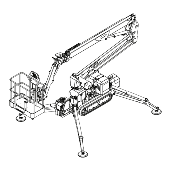
GENERAL DESCRIPTION WARNING The model illustrated may be slightly different from the model in possession. Turret Truck Left track Right track Telescopic boom lifting cylinder Telescopic boom Basket Ground control panel 10. Basket control panel 11. Control levers in the basket 12. -
Page 35: Power Assembly
GENERAL DESCRIPTION TRUCK The truck is the support frame for the machine. It houses the drive and power units. The truck is ! tted with tracks . The machine stabilizers are also installed on the truck. This machine is equiped with an extensible truck system wich allows improved stability and mobility on rough terrain. It is reccomended to keep extended the tracks during traslation movement. - Page 36 GENERAL DESCRIPTION TURRET The turret, mounted on the slewing ring, is rotated by a hydraulic gear . This sustains the entire aerial part of the machine (booms/basket). The ground controls for the aerial part of the machine are located on the side of the turret. These controls are to be used ONLY in the case of emergency.
- Page 37 GENERAL DESCRIPTION The jib consists of two elements in parallelogram con! guration and constitutes another point of articulation of the booms. BASKET One or two operators can occupy the basket. The basket is balanced by a cylinder driven by the telescopic boom. To facilitate passage of the vehicle through narrow gaps and make it easier to climb ramps, the basket is remov- able.
-
Page 38: Safety Devices
SAFETY DEVICES A number of safety devices are installed on the machine for the safety of the operator and the protection of the machine. ACOUSTIC SIGNAL / VISUAL SIGNAL The Buzzer operates every time you are in the condition of driving or moving the stabilizers , so with combustion engine or electric motor ON and with aerial booms completely folded down. -
Page 39: Safety Plates
SAFETY DEVICES STOWED MACHINE MICROSWITCH These microswitches detect when the arm is in the resting position, the turret is aligned with the machine driving direction and stabilizer movement is enabled. SAFETY PLATES See the related paragraph. - Page 40 SAFETY DEVICES OUTREACH LIMITER DEVICE This platform is equipped with an automatic load limiting device. This pressure sensor automatically stops the platform movements whenever the telescopic boom is extended over the allowed limit. RED lamp pos. “2” starts blinking when platform is near to the envelope outreach limits, the. It lights ON when the platform reach the envelope limit and movements are automatically excluded.
- Page 41 SAFETY DEVICES STABILIZATION MICROSWITCHES Each stabiliser foot is provided with a microswitch (1) that ensure a condition of stability on the ground. A series of warning lights signals correct stabilization: when the warning lights (2) go on, the movements related to the aerial part of the machine are enabled.
-
Page 42: Ground Control Panel
GROUND CONTROL PANEL H107 H103 H79A SB40A SA109 SA40 SB76A SB68 SA40 Diesel motor start/voltage connection key switch Three-position selector switch: (0) The motor pump/electropump is stopped and the voltage is disconnected and cuts off power to the electrical panels of the machine (I) The motor pump/electropump is enabled and the voltage is connected (II) The motor pump/electropump is started (the switch is turned to position II only during the start up of the motor, when released it turns to position I).The selection of the electropump is automatic with 220V... - Page 43 GROUND CONTROL PANEL Stowed machine warninglight This warninglight on signals that the machine is stowed: booms are lowered and packed and are aligned to the longitudinal axe of the machine. This condition is COMPULSORY to allow stabilization and traslation functions. Temperature sensor indicator (option) The lamp when “ON”...
- Page 44 A.C. MAINS - BOX & PLUG This panel is present when the machine is provided with an electrical pump powered at 220 or when required 220V on cage. Connection plug to the electric network Magneto-thermic switch With the switch moved to ON the power is available at the cage Magneto-thermic switch With the switch moved to ON the electrical pump is enabled.
- Page 45 CONTROLS FOR MOVEMENT/ STABILISATION NOTE These controls are enabled ONLY with the aerial part retracted. Stabiliser N°4 movement Lowering Raising Stabiliser N°3 movement Lowering Raising Left track running Forward movement Reverse movement Right track running Forward movement Reverse movement Stabiliser N°2 movement Lowering Raising Stabiliser N°1 movement...
- Page 46 CONTROLS FOR MOVEMENT/ STABILISATION Traslation/stabilization commands are mounted on a mobile chassis. This structure have to be raised only during traslation and stabilization operation. After the correct stabilization of the platform and before start working this chassis must be lowered. IMPORTANT Avoid using the platform before lower the command-holding structure in order to avoid collisions with other parts of the machine.
- Page 47 GROUND CONTROL STATION AERIAL PARTS (EMERGENCY CONTROLS) NOTE These controls are enabled ONLY with the lever 1 in the left position. These controls are to be used ONLY in the case of emergency; in fact there is the possibility of blocking the lever 1 using a lock in order to enable only the controls in the basket.
- Page 48 GROUND CONTROL STATION AERIAL PARTS (EMERGENCY CONTROLS) Jib movement lowering raising Basket levelling lowering raising (7) DANGER This control must ONLY be used in case of lost of basket planarity . Basket leveling set-up shall be done by emergency ground controls (by using the yellow lever stored beside of them)with nobody on-board and with the basket near to the ground.
- Page 49 CONTROL PANEL ON THE BASKET SB58A H107A H103A SB39 H99A SB76 SB68A SB40 SB58 Start/stop button for electropump/motorpump With the button pushed in the motor pump or electrical pump is started (depending on the selection made from the ground). RESET side-reach limit - push-button With button pressed allow you to go inside with the extension pulling the hydraulic lever on cage when you are at the edge of the working diagram (H103A switched on).
- Page 50 CONTROL PANEL ON THE BASKET H99A Temperature sensor indicator (option) The lamp when “ON” states the low temperature and do not allow the use of the platform (see section F) 220V/380V/110V electropump indicator The indicator on signals that the machine is connected to the line voltage. H103A Outreach delimiter indicator The RED lamp starts blinking when platform is near to the envelope outreach limit.
- Page 51 CONTROL LEVERS IN THE BASKET NOTE These controls are enabled ONLY after the correct stabilization of the platform. Jib movement lowering raising Telescopic boom extension movement extension in extension out Telescopic boom movement lowering raising Scissor boom movement lowering raising Turret rotation counterclockwise rotation clockwise rotation...
- Page 52 CONTROL LEVERS IN THE BASKET (WITH ROTATION) NOTE These controls are enabled ONLY after the correct stabilization of the platform. Basket rotation clockwise rotation counterclockwise rotation Jib movement lowering raising Telescopic boom extension movement extension in extension out Telescopic boom movement lowering raising Scissor boom movement...
-
Page 53: Other Devices
OTHER DEVICES AIR AND WATER SERVICES On request it is possible to have two intakes for air and/or water installed in the basket. These facilities are connected to a central plant by means of the connections (1). VOLTAGE IN THE BASKET On request it is possible to have an electrical socket (2) installed in the basket. - Page 54 TRANSPORT / TRASLATION WARNING This machine is equiped with an extensible truck system wich allows improved stability and mobility on rough terrain. It is reccomended to keep the tracks extended during traslation movement. TRACKS EXTENSION This operation must be done using stabilizers and with stowed platform. Check that the working area is large enough to lower the stabilizers.
- Page 55 TRANSPORT / TRASLATION The machine may be transported on a truck and/or trailer. BEWARE During transportation, the machine must ALWAYS be secured to the vehicle body with cables or chains. It can be loaded and unloaded in two different ways: lifting the machine through a ramp;...
- Page 56 TRANSPORT / TRASLATION MACHINE SECURING DURING TRANSPORTATION During transportation the machine must ALWAYS be secured to the vehicle body with cables or chains. The hereu- nder photos show the hooking points at chassis(A), legs (B), main platform boom (C). DANGER Always check that the ropes and chains used for are in good working condition.
- Page 57 START UP The self propelled aerial work platform is powered by a diesel or Petrol engine and it can be equipped with electric power pack 220 Vac or 110 Vac in some Countries. A main key selector SA1 is fi tted to the main ground panel. - Turn the SA40 selector to pos.
-
Page 58: Getting Started
GETTING STARTED BEWARE Before using the platform check all safety controls provided in section A04. DRIVING This model of self propelled platform allow the operator to drive by wide or narrow tracks gauge. To enlarge or reduce the gauge please ref. to sec. B03. The driving is allowed with the platform in stowed position and the stowed machine lamp ON( H82 on cage panel –... - Page 59 GETTING STARTED MAKING THE STABILIZATION Take care of locating the platform so that when legs are moved down do not cacth any abstacle causing damage or tipping of the platform. Take care of the visibility operating the legs down to the ground. Ground must be compact and suf! ciently hard to justify the pressure delivered by the platform.
- Page 60 GETTING STARTED HOW TO OPERATE THE AERIAL WORK PLATFORM Max 2 people are allowed on board. The total max allowed weight is 200 kg. Read carefully the SAFETY NORMES and the movements signs applied near to each control station. Read section B09. Operate the extension boom out to release the platform from the stowing U brackets.
- Page 61 GETTING STARTED BASKET LEVELLING COMPENSATOR The aerial platform is equipped with an automatic closed self- levelling hydraulic circuit. It can occur that the basket loose its own horizontality periodically, so it’ll be necessary to compensate and make the allignement throughout the compensation movement. Resetting of the basket can be done by means of its own movement positioned at the control valve ! tted on the back of the platform column.
-
Page 62: Emergency Manoeuvres
EMERGENCY MANOEUVRES FAULTY BASKET CONTROLS This kind of fault can only happen against burst of the high-pressure hydraulic hose connected to the inlet port of basket control valve. To move the basket to the ground, the platform must be operated by the emergency ground controls. Through the key safety locking device, turn the selector on emergency controls position. - Page 63 EMERGENCY MANOEUVRES FAULTY ELECTRIC CIRCUIT This kind of damage involve an emergency procedure to move down people into the basket, throughtout the hand pump. It necessary to enable the emergency ground control station as explained to the previous paragraph. Push & twist the herebelow represented dump valve once the sealing have been removed. Remove the hand pump lever from turret and ! t it in its pump support.
- Page 64 EMERGENCY MANOEUVRES FAULTY ELECTRIC CIRCUIT In case is necessary to lift up the stabilizers in order to close completely the machine, occour to execute the following instructions: Remove the plastic bonnet that covers the area D. Operate the solenoid valve by A cutting the seal and setting on the “push &...
- Page 65 EMERGENCY MANOEUVRES FAULTY ELECTRIC CIRCUIT - Remove the hand pump lever from turret and fi t it in its pump support. - One person is necessary to pump “G” while e second person will operate the ground control station levers “F” for tracks and stabilizers.
- Page 66 EMERGENCY MANOEUVRES If the electric plant does not work, you can start the motor manually as follows: KUBOTA ENGINE The diesel Kubota engine cannot be started by hand. HONDA ENGINE 1. Disconnect the square electric connector fi tted under the general box (pict.1). 2.
-
Page 67: Maintenance
SECTION MAINTENANCE IMPORTANT Replace worn parts with identical, original spare parts. It is forbidden to make modifi cations or to replace parts with components that are not suitable and not author- ized. Before doing any maintenance work and especially maintenance and/or repairs to the electrical system or if it is necessary to do WELDING, COMPLETELY DISCONNECT ALL THE BATTERIES OF THE MACHINE BY REMOVING THE CONNECTOR TERMINALS. - Page 68 Never leave metal tools such as spanners or the like on the machine as these could cause irreparable damage. Replace worn parts with identical, original Platform Basket spare parts. It is forbidden to make modi! cations or to replace parts with components that are not suitable and not authorized...
-
Page 69: Maintenance Schedule
MAINTENANCE SCHEDULE FIRST 10 HOURS OF OPERATION • Replacement of the oil ! lters cartridges on return line and high pressure whether ! tted. (some models are equipped with return oil ! lter only.) • Checking / tightening of screws, nuts and bolts •... - Page 70 GREASING LUBRICATION The lubricators are indicated by RED caps. To re! ll them it is necessary to remove the cap and then pump grease in, until it comes out of the joints which should be moved a few times during this operation. Replace the red cap. The smooth surfaces and the gears should ! rst be cleaned of spent grease with a spatula and then lubricated with fresh grease using a brush.
-
Page 71: Lubricant Table
LUBRICANT TABLE WARNING All maintenance work must be done with the motor switched off and the machine in the rest position. WARNING Do not add oil different to what the manufacturer advises. Grease Grease Hydraulic oil AZOLLA TOTAL MULTIS EP2 MULTIS EP2 ZS 46 ZS 68* MOBIL... - Page 72 SCREW TIGHTENING All screws are to be tightened always with a torque wrench. Excessive tightening of the screws may damage them while insuf! cient tightening defeats their purpose. Each screw has its own speci! c value and the calibration of the torque wrench depends on its diameter and type. If there are a number of screws for the same component (for example the slewing ring, plates, motor-gearboxes) it is necessary to tighten them two at a time in diametrically opposite positions.
- Page 73 SCREW TIGHTENING PRE-LOAD AND TORQUE FOR SCREWS WITH ISO THREAD AND SMALL PITCH Max. pre-load V (kg.) Max. torque Ma (kgm.) Nominal screw diameter 10,9 12,9 10,9 12,9 10 K 12 K 10 K 12 K M 8x1 1750 2470 2960 1,48 2,60...
- Page 74 SUPPLIES DIESEL FUEL OR PETROL GENERATOR MOTOR Re! ll the tank with fuel depending on the motor type See speci! c manual enclosed. HYDRAULIC OIL BATTERIES Re! ll the tank with hydraulic oil (see oil table). Check electrolyte level DRIVE GEARBOX OIL DRIVE GEARS Re! ll with speci! c oil (see pages speci! ed) See speci! c pages.
-
Page 75: Hydraulic Oil Level Check
HYDRAULIC OIL LEVEL CHECK Check the right level directly on the tank. Inspection shall be done when booms and legs are fully stowed and the oil level shall be visible from the sight level indicator (see A). - Page 76 SLIDING BLOCK WEAR AND CHAINS CONTROL Check the wear of the sliding blocks in the extension elements. Replace them if, with the boom and extension ele- ments completely retracted, there is a play exceeding 5 mm between them. BEWARE Replacement of the sliding blocks must be done at an authorized workshop. ATTENTION Periodically check the tension of the telescopic elements extension chains.
- Page 77 SECTION REGISTER AND CONTROL COUPONS...
- Page 78 MAINTENANCE RECORDS AND LOGBOOK This inspection record is released by Platform Basket to the owner of the platform in accordance with EN280:2001+A2:2009. The inspection record is to be considered as a part of the machine and must accompany it throughout its life until...
- Page 79 PlatformBasket on __________________________________ to the company __________________________________________________________ __________________________________________________________ with registered address at According to the conditions agreed, with the technical characteristics, dimensions and functions specifi ed in this instruction manual and in the summary contained in this Register. Platform Basket ___________________...
- Page 80 CHANGE OF OWNERSHIP RECORD SECTION B SUCCESSIVE CHANGES OF OWNERSHIP SUCCESSIVE CHANGES OF OWNERSHIP Date ___________________ The ownership of the WORK PLATFORM ______________________ described in this manual is transferred to the Firm/Company: ______________________________________________________________________________ ______________________________________________________________________________ ______________________________________________________________________________ ______________________________________________________________________________ It is hereby certifi ed that, at the date mentioned above, the technical specifi cations, dimensions and functions of the WORK PLATFORM described in this manual conform to those originally existing and that any modifi...
- Page 81 MAINTENANCE RECORD SPARE PART REPLACEMENT RECORD REPLACEMENT PART RECORD REPLACEMENT OF: _________________________________________________________________ Date _______________________ Manufacturer’s number ______________________ Manufacturer _____________________________ Specifi cations _________________________________________________________________________ REPLACED BY: _________________________________________________________________ Manufacturer’s number ______________________ Manufacturer _____________________________ Specifi cations _________________________________________________________________________ Reason for the replacement_________________________________________________________________ The representative of the company responsible for the replacement _________________________________ The user _________________________________________________________________________...
- Page 82 MAINTENANCE RECORD SPARE PART REPLACEMENT RECORD REPLACEMENT PART RECORD REPLACEMENT OF: _________________________________________________________________ Date _______________________ Manufacturer’s number ______________________ Manufacturer _____________________________ Specifi cations _________________________________________________________________________ REPLACED BY: _________________________________________________________________ Manufacturer’s number ______________________ Manufacturer _____________________________ Specifi cations _________________________________________________________________________ Reason for the replacement_________________________________________________________________ The representative of the company responsible for the replacement _________________________________ The user _________________________________________________________________________...
- Page 83 MAINTENANCE RECORD SPARE PART REPLACEMENT RECORD REPLACEMENT PART RECORD REPLACEMENT OF: _________________________________________________________________ Date _______________________ Manufacturer’s number ______________________ Manufacturer _____________________________ Specifi cations _________________________________________________________________________ REPLACED BY: _________________________________________________________________ Manufacturer’s number ______________________ Manufacturer _____________________________ Specifi cations _________________________________________________________________________ Reason for the replacement_________________________________________________________________ The representative of the company responsible for the replacement _________________________________ The user _________________________________________________________________________...
- Page 84 MAINTENANCE RECORD SPARE PART REPLACEMENT RECORD REPLACEMENT PART RECORD REPLACEMENT OF: _________________________________________________________________ Date _______________________ Manufacturer’s number ______________________ Manufacturer _____________________________ Specifi cations _________________________________________________________________________ REPLACED BY: _________________________________________________________________ Manufacturer’s number ______________________ Manufacturer _____________________________ Specifi cations _________________________________________________________________________ Reason for the replacement_________________________________________________________________ The representative of the company responsible for the replacement _________________________________ The user _________________________________________________________________________...
- Page 85 MAINTENANCE RECORD SPARE PART REPLACEMENT RECORD MECHANISM REPLACEMENT RECORD Date _____________ Description of the element _________________________________ Manufacturer ______________________________ Supplied by _____________________________ Reason for the replacement _____________________________________________________________ The representative of the company responsible for the replacement ____________________________ The user _______________________________________ MECHANISM REPLACEMENT RECORD Date _____________ Description of the element...
- Page 86 MAINTENANCE RECORD SPARE PART REPLACEMENT RECORD MECHANISM REPLACEMENT RECORD Date _____________ Description of the element _________________________________ Manufacturer ______________________________ Supplied by _____________________________ Reason for the replacement _____________________________________________________________ The representative of the company responsible for the replacement ____________________________ The user _______________________________________ MECHANISM REPLACEMENT RECORD Date _____________ Description of the element...
- Page 87 MAINTENANCE RECORD SPARE PART REPLACEMENT RECORD STRUCTURAL PART REPLACEMENT RECORD Date _____________ Description of the element _________________________________ Manufacturer ______________________________ Supplied by _____________________________ Reason for the replacement _____________________________________________________________ The representative of the company responsible for the replacement ____________________________ The user _______________________________________ STRUCTURAL PART REPLACEMENT RECORD _____________ _________________________________...
- Page 88 MAINTENANCE RECORD SPARE PART REPLACEMENT RECORD STRUCTURAL PART REPLACEMENT RECORD Date _____________ Description of the element _________________________________ Manufacturer ______________________________ Supplied by _____________________________ Reason for the replacement _____________________________________________________________ The representative of the company responsible for the replacement ____________________________ The user _______________________________________ STRUCTURAL PART REPLACEMENT RECORD Date _____________...
- Page 89 MAINTENANCE RECORD SPARE PART REPLACEMENT RECORD HYDRAULIC COMPONENTS REPLACEMENT RECORD Date _____________ Description of the element _________________________________ Manufacturer ______________________________ Supplied by _____________________________ Reason for the replacement _____________________________________________________________ The representative of the company responsible for the replacement ____________________________ The user _______________________________________ HYDRAULIC COMPONENTS REPLACEMENT RECORD Date _____________...
- Page 90 MAINTENANCE RECORD SPARE PART REPLACEMENT RECORD HYDRAULIC COMPONENTS REPLACEMENT RECORD Date _____________ Description of the element _________________________________ Manufacturer ______________________________ Supplied by _____________________________ Reason for the replacement _____________________________________________________________ The representative of the company responsible for the replacement ____________________________ The user _______________________________________ HYDRAULIC COMPONENTS REPLACEMENT RECORD Date _____________...
- Page 91 MAINTENANCE RECORD SPARE PART REPLACEMENT RECORD ELECTRICAL COMPONENT REPLACEMENT RECORD Date _____________ Description of the element _________________________________ Manufacturer ______________________________ Supplied by _____________________________ Reason for the replacement _____________________________________________________________ The representative of the company responsible for the replacement ____________________________ The user _______________________________________ ELECTRICAL COMPONENT REPLACEMENT RECORD Date _____________...
- Page 92 MAINTENANCE RECORD SPARE PART REPLACEMENT RECORD ELECTRICAL COMPONENT REPLACEMENT RECORD Date _____________ Description of the element _________________________________ Manufacturer ______________________________ Supplied by _____________________________ Reason for the replacement _____________________________________________________________ The representative of the company responsible for the replacement ____________________________ The user _______________________________________ ELECTRICAL COMPONENT REPLACEMENT RECORD Date _____________...
- Page 93 MAINTENANCE RECORD SPARE PART REPLACEMENT RECORD SAFETY EQUIPMENT REPLACEMENT CARD Date _____________ Description of the element _________________________________ Manufacturer ______________________________ Supplied by _____________________________ Reason for the replacement _____________________________________________________________ The representative of the company responsible for the replacement ____________________________ The user _______________________________________ SAFETY EQUIPMENT REPLACEMENT CARD Date _____________...
- Page 94 MAINTENANCE RECORD SPARE PART REPLACEMENT RECORD SAFETY EQUIPMENT REPLACEMENT CARD Date _____________ Description of the element _________________________________ Manufacturer ______________________________ Supplied by _____________________________ Reason for the replacement _____________________________________________________________ The representative of the company responsible for the replacement ____________________________ _______________________________________ The user SAFETY EQUIPMENT REPLACEMENT CARD Date _____________...
- Page 95 MAINTENANCE RECORD SPARE PART REPLACEMENT RECORD SERIOUS FAILURES Date _____________ Description of the element _________________________________ Manufacturer ______________________________ Supplied by _____________________________ Reason for the replacement _____________________________________________________________ The representative of the company responsible for the replacement ____________________________ The user _______________________________________ SERIOUS FAILURES Date _____________ Description of the element...
- Page 96 MAINTENANCE RECORD SPARE PART REPLACEMENT RECORD SERIOUS FAILURES _____________ _________________________________ Date Description of the element Manufacturer ______________________________ Supplied by _____________________________ Reason for the replacement _____________________________________________________________ ____________________________ The representative of the company responsible for the replacement The user _______________________________________ SERIOUS FAILURES Date _____________ Description of the element...
-
Page 97: Maintenance Records
MAINTENANCE RECORDS The user is obliged to respect the maintenance and inspection schedule in this instruction manual. Operating Date Part Description of action Signature hours _________________________________________________________________________________________ _________________________________________________________________________________________ _________________________________________________________________________________________ _________________________________________________________________________________________ _________________________________________________________________________________________ _________________________________________________________________________________________ _________________________________________________________________________________________ _________________________________________________________________________________________ _________________________________________________________________________________________ _________________________________________________________________________________________ _________________________________________________________________________________________ _________________________________________________________________________________________ _________________________________________________________________________________________ _________________________________________________________________________________________ _________________________________________________________________________________________ _________________________________________________________________________________________ _________________________________________________________________________________________ _________________________________________________________________________________________... - Page 98 MAINTENANCE RECORDS Operating Date Part Description of action Signature hours _________________________________________________________________________________________ _________________________________________________________________________________________ _________________________________________________________________________________________ _________________________________________________________________________________________ _________________________________________________________________________________________ _________________________________________________________________________________________ _________________________________________________________________________________________ _________________________________________________________________________________________ _________________________________________________________________________________________ _________________________________________________________________________________________ _________________________________________________________________________________________ _________________________________________________________________________________________ _________________________________________________________________________________________ _________________________________________________________________________________________ _________________________________________________________________________________________ _________________________________________________________________________________________ _________________________________________________________________________________________ _________________________________________________________________________________________ _________________________________________________________________________________________ _________________________________________________________________________________________ _________________________________________________________________________________________ _________________________________________________________________________________________ _________________________________________________________________________________________ _________________________________________________________________________________________ _________________________________________________________________________________________ _________________________________________________________________________________________ _________________________________________________________________________________________ _________________________________________________________________________________________ _________________________________________________________________________________________ _________________________________________________________________________________________ _________________________________________________________________________________________ _________________________________________________________________________________________ _________________________________________________________________________________________...
- Page 99 MAINTENANCE RECORDS Operating Date Part Description of action Signature hours _________________________________________________________________________________________ _________________________________________________________________________________________ _________________________________________________________________________________________ _________________________________________________________________________________________ _________________________________________________________________________________________ _________________________________________________________________________________________ _________________________________________________________________________________________ _________________________________________________________________________________________ _________________________________________________________________________________________ _________________________________________________________________________________________ _________________________________________________________________________________________ _________________________________________________________________________________________ _________________________________________________________________________________________ _________________________________________________________________________________________ _________________________________________________________________________________________ _________________________________________________________________________________________ _________________________________________________________________________________________ _________________________________________________________________________________________ _________________________________________________________________________________________ _________________________________________________________________________________________ _________________________________________________________________________________________ _________________________________________________________________________________________ _________________________________________________________________________________________ _________________________________________________________________________________________ _________________________________________________________________________________________ _________________________________________________________________________________________ _________________________________________________________________________________________ _________________________________________________________________________________________ _________________________________________________________________________________________ _________________________________________________________________________________________ _________________________________________________________________________________________ _________________________________________________________________________________________ _________________________________________________________________________________________...
- Page 100 SECTION INTEGRATION FOR RADIO COMMAND VERSION...
- Page 101 EA01 SIGNS AFFIXED TO THE MACHINE Cage controls Ground controls (Emergency) Ground control (Traslation and stabilization). Danger hot surface.
-
Page 102: General Description
EA02 GENERAL DESCRIPTION WARNING The model illustrated may be slightly different from the model in possession. Turret Truck Left track Right track Telescopic boom lifting cylinder Telescopic boom Basket Ground control panel 10. Basket control panel 11. Control levers in the basket 12. - Page 103 EA03 CONTROLS FOR TRAVELLING / STABILISATION NOTE These controls are enabled ONLY with the aerial part stowed. Stabiliser N°4 movement Rabbit / turtle selector (only with double speed hydraulic motor) Raising turtle (slow speed) Lowering rabbit (fast speed) Stabiliser N°3 movement Raising Lowering Left track running...
- Page 104 EA03 CONTROLS FOR TRAVELLING/ STABILISATION IMPORTANT! Is strictly recommended to operate travelling and stabilizing staing at the right distance from the machine, the machine tip over can cause serious damages to the operator. Proceed as following instructions in order to enable the operations: •...
- Page 105 EA03 CONTROLS FOR TRAVELLING/ STABILISATION Engine Start / Stop Start of the endothermic/electric motor Stop of the endothermic/electric motor Emergency push button If pressed it switches OFF the transmitting consolle and disables all the functions present on it. Rabbit / turtle selector (speed selection with double speed motor, if present) turtle (slow speed) rabbit (high speed) Rabbit / turtle selector + button n°4 (automatic stabilization/destabilization selection, if present)
- Page 106 EA03 CONTROLS FOR TRAVELLING/ STABILISATION Battery change Extract the battery A from the bottom side of the transmitter, open the lid B and take out the spare battery, fi t the empty battery instead of the full charge battery and connect the full charged one in the transmitter. The battery is automatically charged by means of the battery charger C even if the electric installation is switched OFF, once the charge is fi...
- Page 107 EA04 EMERGENCY MANOEUVRE FAULTY ELECTRIC CIRCUIT This kind of damage involve an emergency procedure to move down people into the basket, throughtout the hand pump. It necessary to enable the emergency ground control station as explained to the previous paragraph. Push &...
- Page 108 EA04 EMERGENCY MANOEUVRE FAULTY ELECTRIC CIRCUIT In case is necessary to lift up the stabilizers in order to close completely the machine, occour to execute the following instructions: Remove the plastic carter over the area D. Push with a screwdriver the pin on the valve A. Keep pressed the pin during the emergency manoeuvre.
- Page 109 EA04 EMERGENCY MANOEUVRE FAULTY ELECTRIC CIRCUIT - Remove the hand pump lever from turret and ! t it in its pump support. - One person is necessary to pump G while e second person will operate the ground control station levers F for tracks and stabilizers.
- Page 110 SECTION INTEGRATION FOR CABLE COMMAND VERSION...
- Page 111 EB01 SIGNS AFFIXED TO THE MACHINE Cage controls Ground controls (Emergency) Ground control (stabilization). Ground control (Traslation).
- Page 112 EB02 GENERAL DESCRIPTION WARNING The model illustrated may be slightly different from the model in possession. Turret Truck Left track Right track Telescopic boom lifting cylinder Telescopic boom Basket Ground control panel 10. Basket control panel 11. Control levers in the basket 12.
- Page 113 EB03 CONTROLS FOR TRAVELLING HL119 YV95-97 SB119 YV91-93 NOTE These controls are enabled ONLY with the aerial part retracted. Left track movement lever Forward Back Right track movement lever Forward Back SB119 Emergency button - OFF panel When pressed the wired panel stops immediately. To reset button turn it following arrows.
- Page 114 EB03 CONTROLS FOR TRAVELLING - Verify the right plug of cable between RT connector of the ground panel and to the RNT remote control unit connector. - Move the SA40 switch (ground control Panel) to “ground station” to work the remote control. The green indicator light on the receiver comes on.
- Page 115 EB03 CONTROLS FOR TRAVELLING ATTENTION Carry out translation operations with the machine’s aerial part obligatorily closed (antenna closed, extension in and arm lowered; the arm can only be raised if slope is exceeded). - Start the engine. - Move the switch (SA40) to “ground position”. SA40 - Proceed with closing the stabiliser feet.
- Page 116 EB03 CONTROLS FOR TRAVELLING NOTE These controls are enabled ONLY with the aerial part retracted. Stabiliser N°1 movement Lowering Raising Stabiliser N°2 movement Lowering Raising Stabiliser N°3 movement Lowering Raising Stabiliser N°4 movement Lowering Raising...
- Page 117 EB03 CONTROLS FOR TRAVELLING SA40 H107A - Start the engine. - Verify the longitudinal alignment between platform booms and chassis. - Turn the switch SA40 to “ground position”. - operate the stabilization control valve acting the levers pos. 1-2 at the same time until the legs are down to the ground and the relevant lamps H50-H51 are both switched ON.
- Page 118 EB04 EMERGENCY MANOEUVRE Situation where there is fault with the main electrical system and it is impossible to start up the pumps/ main engines - Turn the selector (SA40) to “ground controls”. SA40 - Remove the plastic carter over the area D. To bypass the valve (YV83): - Press and turn the pin clockwise to keep it in a lowered, blocked position.
- Page 119 EB04 EMERGENCY MANOEUVRE - Press YV82 and keep pressed. - Move the stabilisers from the carriage distributor using the manual pump (B) or, if present and operational, the emergency electric pump 12 V SB76A. YV82 SB76A By keeping the YV82 valve pressed you can slowly translate manoeuvring the tracks with the emergency distributor lever.
- Page 120 SECTION OPTION...
-
Page 121: Temperature Sensor
TEMPERATURE SENSOR Under the main control panel is positioned the temperature sensor that monitors the ambient temperatu- The temperature sensor is set with two steps: - w h e n t h e t e m p e r a t u r e r e a c h e s - 1 5 ° C ( t h e t e m p e r a t u r e i s d i s p l a y e d o n t h e s e n - s o r ) , t h e o p e r a t o r i s n o t i f i e d b y a i n t e r m i t t e n t l y a c o u s t i c s i g n a l . - Page 122 BASKET WITH LOAD CELL The basket is provided with a load cell which blocks movement of the machine when the weight inside the basket exceeds 200 kg with a +10% tolerance. If the basket load limiting device trips, it blocks all movements of the machine. To resume normal operation, the excess load must be eliminated from the basket.
- Page 123 HORN A horn has been placed near the oil tank which the operator uses to warn that the machine is moving, by pressing the specifi c button (SB39) on the control board of the basket. SB39...
- Page 124 The undersigned Simona Iraci Tobbi born in Reggio Emilia on 31.07.1982 and living in Cadelbosco Sopra (Reggio Emilia) Via Panini n.15 , President of the board of directors of PLATFORM BASKET Srl with head offi ces in POVIGLIO (REGGIO EMILIA) Via Grande 27, manufacturer of the following Machine: MAN LIFTING DEVICE WITH RISK OF VERTICAL FALLS GREATER THAN 3 M.
- Page 125 The undersigned Simona Iraci Tobbi born in Reggio Emilia on 31.07.1982 and living in Cadelbosco Sopra (Reggio Emilia) Via Panini n.15 , President of the board of directors of PLATFORM BASKET Srl with head offi ces in POVIGLIO (REGGIO EMILIA) Via Grande 27, manufacturer of the following Machine: MAN LIFTING DEVICE WITH RISK OF VERTICAL FALLS GREATER THAN 3 M.
- Page 126 The undersigned Simona Iraci Tobbi born in Reggio Emilia on 31.07.1982 and living in Cadelbosco Sopra (Reggio Emilia) Via Panini n.15 , President of the board of directors of PLATFORM BASKET Srl with head offi ces in POVIGLIO (REGGIO EMILIA) Via Grande 27, manufacturer of the following Machine: MAN LIFTING DEVICE WITH RISK OF VERTICAL FALLS GREATER THAN 3 M.
Need help?
Do you have a question about the SPIDER 18.90 PRO and is the answer not in the manual?
Questions and answers
5 flashes on the message light