Table of Contents
Advertisement
Quick Links
Advertisement
Chapters
Table of Contents

Related Manuals for AUTO GYRO MTOsport 2017


Summary of Contents for AUTO GYRO MTOsport 2017
- Page 1 Pilot Operating Handbook MTOsport 2017 | Rotax 915 IS...
- Page 2 Pilot Operating Handbook for Gyroplane MTOsport Model 2017 915iS AutoGyro_POH_MTOsport-Model2017 915 Revision 1.1 – Issue Date 14.08.2019 Pre-pages 1...
- Page 3 All rights reserved. Under the copyright laws, this manual may not be copied, in whole or in part, without the written consent of AutoGyro GmbH. AutoGyro reserves the right to change or improve its products and to make changes in the content of this manual without obligation to notify any person or organisation of such changes or improvements.
- Page 4 Pilot Operating Handbook for Gyroplane MTOsport Model 2017 915 iS Model: ______________________________________________ Serial number: ______________________________________________ Registration: ______________________________________________ Type certificate number: ______________________________________________ Aircraft manufacturer and type certificate holder: AutoGyro GmbH Dornierstraße 14 D-31137 Hildesheim Tel.: +49 (0) 51 21 / 8 80 56-00 Fax: +49 (0) 51 21 / 8 80 56-19 Distribution partner: ______________________________________________...
- Page 5 REVISION LOG Rev. Inserted by Date Signature AutoGyro GmbH 14.08.2019 Issue 1.1 includes minor updates and corrections, marked by a solid bar in the margin. AutoGyro_POH_MTOsport-Model2017 915 Revision 1.1 – Issue Date 14.08.2019 Pre-pages 4...
-
Page 6: Table Of Contents
Pilot Operating Handbook Table of Contents MTOsport Model 2017 List of Effective Pages CONTENTS SECTION 1 - GENERAL....................1-1 Introduction....................1-1 Certification ....................1-1 Performance Data and Operating Procedures ..........1-1 Definition of Terms ..................1-2 Important Note....................1-2 Three-view of the MTOsport Model 2017 915 iS ..........1-3 Description .................... - Page 7 Pilot Operating Handbook Table of Contents MTOsport Model 2017 List of Effective Pages 3.14 Alternative Method of Engine Shut-Down ............ 3-13 3.15 Failure of Variable Pitch Propeller (if installed) ..........3-13 SECTION 4 - NORMAL PROCEDURES ................4-1 Airspeeds for Safe Operation ................ 4-1 Preparation for Flight..................
- Page 8 Pilot Operating Handbook Table of Contents MTOsport Model 2017 List of Effective Pages Airframe and Undercarriage................7-1 Doors, Windows and Exits ................7-1 Fuel System ....................7-1 Pneumatic System..................7-3 Power Plant ....................7-4 Propeller......................7-4 Rotor System (TOPP)..................7-5 Flight Controls ....................7-5 7.10 Electrical System ...................
- Page 9 Pilot Operating Handbook Table of Contents MTOsport Model 2017 List of Effective Pages 9-1.8 Handling and Servicing ..................2 9-2 Lights ..........................1 9-2.1 General ......................1 9-2.2 Limitations......................2 9-2.3 Emergency Procedures..................2 9-2.4 Normal Procedures ..................2 9-2.5 Performance ....................
- Page 10 Pilot Operating Handbook Table of Contents MTOsport Model 2017 List of Effective Pages LIST OF EFFECTIVE PAGES Page(s) Rev. Date Page(s) Rev. Date 1-1 to 1-8 14.08.2019 8-1 to 8-11 14.08.2019 2-1 to 2-14 14.08.2019 9-1 – 1 to 4 14.08.2019 3-1 to 3-12 14.08.2019...
- Page 11 Pilot Operating Handbook Table of Contents MTOsport Model 2017 List of Effective Pages INTENTIONALLY LEFT BLANK AutoGyro_POH_MTOsport-Model2017 915 Revision 1.1 – Issue Date 14.08.2019 Index / LOEP 6...
- Page 12 Pilot Operating Handbook SECTION 1 MTOsport Model 2017 GENERAL CONTENTS Introduction....................1-1 Certification ....................1-1 Performance Data and Operating Procedures ..........1-1 Definition of Terms ..................1-2 Important Note....................1-2 Three-view of the MTOsport Model 2017............1-3 Description ....................1-4 Technical Data ....................
- Page 13 Pilot Operating Handbook SECTION 1 MTOsport Model 2017 GENERAL INTENTIONALLY LEFT BLANK AutoGyro_POH_MTOsport-Model2017 915 Revision 1.1 – Issue Date 14.08.2019 1-ii...
-
Page 14: Section 1 - General
Pilot Operating Handbook SECTION 1 MTOsport Model 2017 GENERAL SECTION 1 - GENERAL Introduction This manual is designed as an operating guide for pilots, instructors, and owners/operators, providing information for the safe and efficient operation of this gyroplane. It includes material required to be furnished to the pilot by the competent certification authority. -
Page 15: Definition Of Terms
Pilot Operating Handbook SECTION 1 MTOsport Model 2017 GENERAL Definition of Terms This manual uses WARNINGs, CAUTIONs and NOTEs in bold capital letters to indicate especially critical and important instructions. Additionally, the colour of the panel (red, yellow, and grey shading) highlights the significance of the instruction. Definitions for each term are given below. -
Page 16: Three-View Of The Mtosport Model 2017 915 Is
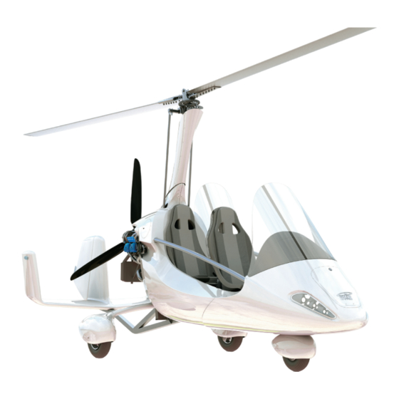
Pilot Operating Handbook SECTION 1 MTOsport Model 2017 GENERAL Three-view of the MTOsport Model 2017 915 iS 5.25 m 2.76 m AutoGyro_POH_MTOsport-Model2017 915 Revision 1.1 – Issue Date 14.08.2019... -
Page 17: Description
Pilot Operating Handbook SECTION 1 MTOsport Model 2017 GENERAL Description General Characteristics Gyroplane with nose gear wheel chassis Framework manufactured from inert-gas welded stainless steel tube Two-seat tandem configuration Main landing gear with GRP (glass fibre reinforced plastic) spring spar and hydraulic disc brakes ... -
Page 18: Engine
Pilot Operating Handbook SECTION 1 MTOsport Model 2017 GENERAL 1.10 Engine ROTAX 915 iS 4-cylinder, four-stroke spark-ignition engine with opposed cylinders with turbo charger Liquid cooled cylinder heads Air cooled cylinders Dry sump forced lubrication with separate oil tank ... -
Page 19: Unit Conversion
Pilot Operating Handbook SECTION 1 MTOsport Model 2017 GENERAL 1.12 Unit Conversion Multiply to obtain kts (knots) 1.852 km/h km/h (kilometres per hour) 0.54 mph (miles per hour) 1.61 km/h km/h (kilometres per hour) 0.62 ft (feet) 0.305 m (metres) 3.28 AutoGyro_POH_MTOsport-Model2017 915 Revision 1.1 –... -
Page 20: Abbreviations And Terminology
Pilot Operating Handbook SECTION 1 MTOsport Model 2017 GENERAL 1.13 Abbreviations and Terminology Anti-Collision Light Above Ground Level Air Traffic Control BCAR British Civil Airworthiness Requirements Bauvorschriften für Ultraleichte Tragschrauber – German design specification for microlight gyroplanes Calibrated AirSpeed – indicated speed corrected for installation errors Counter Clock Wise Centre of Gravity Coolant Temperature... - Page 21 Pilot Operating Handbook SECTION 1 MTOsport Model 2017 GENERAL Pounds (weight) Light Emitting Diode Left-Hand LOEP List Of Effective Pages Litre Ltr/hr Litres per Hour metres Manifold Absolute Pressure maximum Maximum Continuous Power minimum Metres per second MTOM Maximum Take-Off Mass MTOW Maximum Take-Off Weight Outside Air Temperature...
- Page 22 Pilot Operating Handbook SECTION 1 MTOsport Model 2017 GENERAL W&B Weight and Balance years AutoGyro_POH_MTOsport-Model2017 915 Revision 1.1 – Issue Date 14.08.2019...
- Page 23 Pilot Operating Handbook SECTION 2 MTOsport Model 2017 LIMITATIONS CONTENTS General ......................2-1 Environmental Limitations................2-2 Colour Code for Instrument Markings ............2-3 Airspeed Limitations and Instrument Markings..........2-4 Rotor Speed Limitations and Instrument Markings.........2-4 Power Plant Limitations and Instrument Markings.......... 2-5 Weight and Balance ..................
- Page 24 Pilot Operating Handbook SECTION 2 MTOsport Model 2017 LIMITATIONS INTENTIONALLY LEFT BLANK AutoGyro_POH_MTOsport-Model2017 Revision 1.1 – Issue Date 14.08.2019 2-ii...
-
Page 25: Section 2 - Limitations
Pilot Operating Handbook SECTION 2 MTOsport Model 2017 LIMITATIONS SECTION 2 - LIMITATIONS This section contains operating limitations, instrument markings and basic placards which are required for safe operation of the gyroplane, including its engine, and standard equipment or systems. General WARNING The operation of a gyroplane demands professional pilot instruction and... -
Page 26: Environmental Limitations
In common with other aircraft of this type the MTOsport 2017 utilises a non- certified engine. This means that there may be a higher risk of engine failure than in a certified aircraft, with the associated risks of damage or injury as the result of an unplanned landing. -
Page 27: Colour Code For Instrument Markings
Pilot Operating Handbook SECTION 2 MTOsport Model 2017 LIMITATIONS CAUTION Care must be used operating at high altitudes, as it is possible to overspeed the engine in level flight at max power. Take care to monitor the engine rpm gauge. Aircraft and engine performance degrades with decreasing pressure altitude and increasing temperatures. -
Page 28: Airspeed Limitations And Instrument Markings
Pilot Operating Handbook SECTION 2 MTOsport Model 2017 LIMITATIONS Airspeed Limitations and Instrument Markings Air Speed Marking 195 km/h Never Exceed Speed 120 mph Red radial 105 KIAS 120 – 195 km/h Caution Range Yellow arc 75 – 120 mph 65 –... -
Page 29: Power Plant Limitations And Instrument Markings
Pilot Operating Handbook SECTION 2 MTOsport Model 2017 LIMITATIONS Power Plant Limitations and Instrument Markings Engine Speed Marking Maximum engine speed Red radial 5800 RPM 5 minute take-off power regime Yellow arc 5500 – 5800 RPM Maximum continuous power Green arc 1400 –... - Page 30 Pilot Operating Handbook SECTION 2 MTOsport Model 2017 LIMITATIONS Coolant temp notes from Rotax OM Parameter Coolant temperature -20 °C (-4 °F) 90 °C (194 °F) at ground idle, start procedure and warm Coolant temperature 120 °C (248 °F) 40 °C (104 °F) For this at normal operation aircraft 50degC is taken as the manufacturers minimum.
- Page 31 Pilot Operating Handbook SECTION 2 MTOsport Model 2017 LIMITATIONS Oil temperature notes from Rotax OM Parameter Oil temperature at -20 °C (-4 °F) 100 °C (212 °F) ground idle, start procedure and warm up Oil temperature at 50 °C / 120 °F 130 °C (266 °F) normal operation AutoGyro_POH_MTOsport-Model2017 915 Revision 1.1 –...
-
Page 32: Weight And Balance
Pilot Operating Handbook SECTION 2 MTOsport Model 2017 LIMITATIONS Weight and Balance 2.7.1 Weight Limits Maximum take-off mass (MTOM):............560 kg* *see applicable country Type Approval or Type Certificate Data Sheet CAUTION The take-off weight is the total weight of the gyroplane including empty weight, optional/additional equipment, occupants, fuel, and luggage at take-off. -
Page 33: Flight Crew
The aft control stick should be removed unless the passenger seat is occupied by a qualified flight instructor. Kinds of Operation Day-VFR operation is approved for all MTOsport 2017 gyroplanes Day and Night VFR operation is permitted where the aircraft is fitted with the required minimum additional night equipment. -
Page 34: Fuel
Pilot Operating Handbook SECTION 2 MTOsport Model 2017 LIMITATIONS WARNING Side slip may be performed only with proper training and within safe boundaries. Use gentle pedal input for initiation and stabilization. Do not rely on airspeed indication in side slip. Never perform abrupt control stick input into the direction of motion. -
Page 35: Operation With Leaded Avgas Fuels
Pilot Operating Handbook SECTION 2 MTOsport Model 2017 LIMITATIONS When refuelling, attach the earth line to the exhaust pipe to prevent static electrical discharges! NOTE AutoGyro does not recommend E10 for permanent or sustained use. Don´t let E10 remain in the fuel system for an unnecessarily long time or for long-term storage! For operational constraints and maintenance aspects when using preferred fuel and alternate fuel, refer to the engine manufacturer’s manual. -
Page 36: Minimum Equipment
Pilot Operating Handbook SECTION 2 MTOsport Model 2017 LIMITATIONS 2.11 Minimum Equipment The following equipment must be operative for day VFR flight: Air speed indicator Altimeter Compass Rotor RPM indicator Engine instruments (oil pressure, RPM, coolant temperature/ECT) ... - Page 37 Pilot Operating Handbook SECTION 2 MTOsport Model 2017 LIMITATIONS In clear view of the pilot (if equipment installed): Boost switch (if installed): AutoGyro_POH_MTOsport-Model2017 915 Revision 1.1 – Issue Date 14.08.2019 2-13...
- Page 38 Pilot Operating Handbook SECTION 2 MTOsport Model 2017 LIMITATIONS Flight control stick head: Front seat: Aft seat: AutoGyro_POH_MTOsport-Model2017 915 Revision 1.1 – Issue Date 14.08.2019 2-14...
- Page 39 Pilot Operating Handbook SECTION 2 MTOsport Model 2017 LIMITATIONS Nose compartment: Fuel filler neck: Oil reservoir: AutoGyro_POH_MTOsport-Model2017 915 Revision 1.1 – Issue Date 14.08.2019 2-15...
- Page 40 Pilot Operating Handbook SECTION 2 MTOsport Model 2017 LIMITATIONS Coolant header tank: Battery charging port: Keel tube fin: AutoGyro_POH_MTOsport-Model2017 915 Revision 1.1 – Issue Date 14.08.2019 2-16...
- Page 41 Pilot Operating Handbook SECTION 3 MTOsport Model 2017 EMERGENCY PROCEDURES CONTENTS Engine Failure ....................3-1 Air Restart Procedure ..................3-2 Landing into Trees or High Vegetation............3-3 Degradation of Engine Power ................ 3-3 Evacuating the Aircraft................... 3-3 Engine Fire....................3-3 Off-field Landing ....................
- Page 42 Pilot Operating Handbook SECTION 3 MTOsport Model 2017 EMERGENCY PROCEDURES INTENTIONALLY LEFT BLANK AutoGyro_POH_MTOsport-Model2017 915 Revision 1.1 – Issue Date 14.08.2019 3-ii...
-
Page 43: Section 3 - Emergency Procedures
Pilot Operating Handbook SECTION 3 MTOsport Model 2017 EMERGENCY PROCEDURES SECTION 3 - EMERGENCY PROCEDURES This chapter contains the check lists and procedures to be executed in emergency situations. Emergencies due to defects of the gyroplane or its engine are extremely seldom if the aircraft is checked thoroughly before each flight and continuously maintained. -
Page 44: Air Restart Procedure
Pilot Operating Handbook SECTION 3 MTOsport Model 2017 EMERGENCY PROCEDURES Engine failure at night Consider wind speed and direction Both landing lights should be turned on by 400ft and on below 400ft. Select a suitable landing site – the landing lights make the ground visible in full dark from around 200ft ... -
Page 45: Landing Into Trees Or High Vegetation
Pilot Operating Handbook SECTION 3 MTOsport Model 2017 EMERGENCY PROCEDURES Landing into Trees or High Vegetation Assume the surface of the treetops or vegetation as level Plan touch-down and flare with minimum rate of descent As soon as the wheels contact the vegetation bring the rotor disc to level attitude to avoid partial blade tip contact with vegetation ... -
Page 46: Off-Field Landing
Pilot Operating Handbook SECTION 3 MTOsport Model 2017 EMERGENCY PROCEDURES Off-field Landing A precautionary landing at a non-prepared site may be performed at pilot’s discretion in order to avoid unexpected weather, in case of severe illness of the pilot or a passenger, or if technical defects are suspected, for example sudden and severe rotor vibrations. -
Page 47: Trim Runaway
Pilot Operating Handbook SECTION 3 MTOsport Model 2017 EMERGENCY PROCEDURES effects or a possible negative yaw-roll coupling. Approach landing site with wide and shallow turns. 3.8.4 Trim Runaway Failure of a trim selector switch or pneumatic valve may result in trim runaway (where the trim system runs to one extreme and pushes the control stick accordingly). - Page 48 Pilot Operating Handbook SECTION 3 MTOsport Model 2017 EMERGENCY PROCEDURES Engine and Propeller Vibration Vibration in this area will change with engine rpm, and can therefore be affected and isolated by the pilot. The propeller is normally balanced to less than 0.1ips, meaning low vibration.
-
Page 49: Other Equipment Failure
Pilot Operating Handbook SECTION 3 MTOsport Model 2017 EMERGENCY PROCEDURES 3.8.7 Other Equipment Failure Good judgement must be used in monitoring instruments, and timely action taken should a reading be in doubt. If in doubt, make a precautionary landing and resolve the issue rather than continuing a flight. - Page 50 Pilot Operating Handbook SECTION 3 MTOsport Model 2017 EMERGENCY PROCEDURES Oil pressure, oil temp and ECT/coolant temp Abnormal indication of one gauge can indicate an engine fault or simply a gauge fault. Watching the other gauges will indicate the likely failure mode. For example: Abnormal indication Probable failure mode Gauge suddenly goes to full scale...
-
Page 51: Warning Lights
Pilot Operating Handbook SECTION 3 MTOsport Model 2017 EMERGENCY PROCEDURES Warning Lights 3.9.1 Water (red) Engine water temperature has exceeded 120 °C. The engine may be damaged and fail shortly. Reduce power and increase airspeed. If condition cannot be corrected, land as soon as practicable. -
Page 52: Low Volt (Amber)
Pilot Operating Handbook SECTION 3 MTOsport Model 2017 EMERGENCY PROCEDURES NOTE A GEN1 failure is only indicated where both lamps flash. When only one is flashing, then a different failure mode is indicated. See 3.9.8 If GEN2 supply fails, there is no direct indication. However, because the aircraft is operating on battery power alone, the ‘LOW VOLT’... -
Page 53: Fuel P. (Amber)
Pilot Operating Handbook SECTION 3 MTOsport Model 2017 EMERGENCY PROCEDURES Blinking Intended take-off run with low rotor RPM – danger of blade flapping Reduce power immediately, and stop if take-off has started. Re-apply the pre-rotator and increase rotor RPM first. If the correct take-off rotor RPM cannot be reached, abort take-off. 3.9.7 Fuel P. -
Page 54: Parameters Out Of Limits
Pilot Operating Handbook SECTION 3 MTOsport Model 2017 EMERGENCY PROCEDURES Flashing One way flight to Flight is possible to your maintenance hangar destination at your own permissible discretion. Flight not permissible Land the aircraft* Flashing Flashing Flight not permissible Land the aircraft* Flashing Flight not permissible Land the aircraft*... -
Page 55: Rotor System
Pilot Operating Handbook SECTION 3 MTOsport Model 2017 EMERGENCY PROCEDURES 3.11 Rotor System The entire rotor system including its rotor head with blade attachments and the corresponding components of the flight controls have to be inspected and maintained carefully. If any undue vibration or unusual behaviour is experienced a precautionary landing should be considered. - Page 56 Pilot Operating Handbook SECTION 3 MTOsport Model 2017 EMERGENCY PROCEDURES Run-away to FINE: RPM will increase and propeller pitch will stop in full FINE position. Reduce power if needed, to stay within RPM limits. Run-away to COARSE: RPM will decrease until propeller pitch stops in full COARSE position.
- Page 57 Pilot Operating Handbook SECTION 4 MTOsport Model 2017 NORMAL PROCEDURES CONTENTS Airspeeds for Safe Operation.................4-1 Preparation for Flight ..................4-1 Daily or Pre-flight Checks ................4-1 Before Boarding .................... 4-5 Before Starting Engine................... 4-6 Starting Engine....................4-6 Taxi and Run-up .................... 4-7 Take-off Procedure..................
- Page 58 Pilot Operating Handbook SECTION 4 MTOsport Model 2017 NORMAL PROCEDURES INTENTIONALLY LEFT BLANK AutoGyro_POH_MTOsport-Model2017 915 Revision 1.1 – Issue Date 14.08.2019 4-ii...
-
Page 59: Section 4 - Normal Procedures
Pilot Operating Handbook SECTION 4 MTOsport Model 2017 NORMAL PROCEDURES SECTION 4 - NORMAL PROCEDURES This section contains check list items, instructions and procedures for the operation of the gyroplane. However, these procedures do not replace the pilot’s appreciation of the individual situation. - Page 60 Pilot Operating Handbook SECTION 4 MTOsport Model 2017 NORMAL PROCEDURES The following checks must be carried out before each flight. However, if the gyroplane is operated by a single pilot or within an organization where the checks are performed by or under the supervision of qualified personnel, check list items marked with a preceding ‘ʘ’...
- Page 61 Pilot Operating Handbook SECTION 4 MTOsport Model 2017 NORMAL PROCEDURES Gimbal head and rotor head Upper control rod ends..........No play, tight and secure Gimbal head attachment lugs and weld seams ........No cracks Gimbal head bolts (2x) ........... Tight, split pin installed ʘ...
- Page 62 Pilot Operating Handbook SECTION 4 MTOsport Model 2017 NORMAL PROCEDURES Station 5 (engine, LH side) ʘ Main frame and welded joints ........No cracks, no deformation ʘ Main gear spring spar attachment......No cracks, attachment tight Main gear spring spar, underside............No cracks Oil cooler and hoses ............Condition, fittings tight Fuel level.............Cross-check with cockpit indication ʘ...
-
Page 63: Before Boarding
Pilot Operating Handbook SECTION 4 MTOsport Model 2017 NORMAL PROCEDURES Station 9 (nose) General appearance ..................OK Pitot tube .................. Clean and open Windshield ..............Condition and cleanliness Storage compartment in nose section ........Closed and locked ʘ Nose wheel...............Condition and air pressure Station 10 (pilot station, RH side) Static port ................. -
Page 64: Before Starting Engine
Pilot Operating Handbook SECTION 4 MTOsport Model 2017 NORMAL PROCEDURES Passenger ..........Briefed and secure (helmet, hair, gear) Aft seat belts................. Fastened and tight Loose objects ..............Removed / secured Luggage bags ..................Secured Pilot station: Loose objects ..............Removed / secured Document bag .................. -
Page 65: Taxi And Run-Up
Pilot Operating Handbook SECTION 4 MTOsport Model 2017 NORMAL PROCEDURES Propeller and area .................. “Clear” Starter (with right hand, left hand on throttle/brake)........ Engage Hold starter until engine fires, but for a maximum of 10 seconds. Generally the engine fires immediately. In case of an unsuccessful starting attempt check all preconditions. - Page 66 Pilot Operating Handbook SECTION 4 MTOsport Model 2017 NORMAL PROCEDURES maintained in forward centre position. When taxiing on uneven ground, use particular caution and hold control stick so as to avoid the blades or control system hitting their mechanical stops. Carry out engine run-up in an area with least risk to individuals and other airport ground traffic, preferably headed into the wind.
-
Page 67: Take-Off Procedure
Pilot Operating Handbook SECTION 4 MTOsport Model 2017 NORMAL PROCEDURES Low fuel pressure is indicated by the LED warning lamp indicating red. Excessive pressure is indicated by flashing red. The light must remain off when either one or both pumps are on. Functional check VPP (if installed)........execute (see 9-1.4.3) Set Prop to FINE (MAX RPM) Electronic Primary Flight display, where fitted. - Page 68 Pilot Operating Handbook SECTION 4 MTOsport Model 2017 NORMAL PROCEDURES If the CLUTCH light is flashing, check that the rotor rpm is sufficient and consider aborting the take-off run. WARNING Before activating the pre-rotator, check area is clear and ensure that the passenger’s hair or loose garment cannot be caught in the pre-rotator drive shaft (where exposed).
-
Page 69: Take-Off Run
Pilot Operating Handbook SECTION 4 MTOsport Model 2017 NORMAL PROCEDURES CAUTION Do not try to pull the stick back with the pre rotator engaged and under load. The drive torque will prevent the system sliding joints from moving, resulting in damage to the drive system. -
Page 70: Climb
Pilot Operating Handbook SECTION 4 MTOsport Model 2017 NORMAL PROCEDURES WARNING Gyroplanes are fully controllable at very low speeds without exhibiting any signs of wing stall or soft flight controls, as it would be perceived in a fixed wing aircraft. However, operation ‘behind the power curve’ may have fatal consequences during take-off, initial climb or in any other situation within close ground proximity. -
Page 71: Approach
Pilot Operating Handbook SECTION 4 MTOsport Model 2017 NORMAL PROCEDURES 4.13 Approach Switch ON second fuel pump P2 (if installed) Set variable pitch propeller (if installed) to FINE (MAX RPM) Check wheel brake unlocked Maintain and trim approach speed ... -
Page 72: Go-Around
Pilot Operating Handbook SECTION 4 MTOsport Model 2017 NORMAL PROCEDURES CAUTION Touching down with the nose wheel pointing left or right, and with a run-on speed, will cause the wheel to ‘grab’ in that direction. If left uncorrected the aircraft will try to turn in that direction, possibly resulting in a roll-over. Always lower the nose at low ground speed, with the nose wheel straight. -
Page 73: Engine Shut-Down
Pilot Operating Handbook SECTION 4 MTOsport Model 2017 NORMAL PROCEDURES NOTE It is advisable to let the rotor spin down while the gyroplane is at a complete stop. However, in order to vacate the runway, it is possible to taxi while the rotor is spinning down. -
Page 74: Special Procedure: Slow Speed Sink And Recovery
Pilot Operating Handbook SECTION 4 MTOsport Model 2017 NORMAL PROCEDURES wheel brakes locked) In case of a slipping clutch (CLUTCH light), reduce power to match engine to rotor speed With the stick moved slightly aft (which will disengage the pre-rotator), release the wheel brake without reducing engine power ... -
Page 75: Noise Abatement
Pilot Operating Handbook SECTION 4 MTOsport Model 2017 NORMAL PROCEDURES 4.22 Noise Abatement A positive attitude towards residents and environmental-friendly flying supports the reputation and acceptance of aviation in general, and gyroplanes in particular. When compared to other airplanes the noise of a gyroplane is sometimes perceived as unpleasant although it meets the same or sometimes more stringent noise emission requirements. - Page 76 Pilot Operating Handbook SECTION 4 MTOsport Model 2017 NORMAL PROCEDURES INTENTIONALLY LEFT BLANK AutoGyro_POH_MTOsport-Model2017 915 Revision 1.1 – Issue Date 14.08.2019 4-18...
- Page 77 Pilot Operating Handbook SECTION 5 MTOsport Model 2017 PERFORMANCE CONTENTS Demonstrated Operating Temperature ............5-1 Airspeed Correction..................5-1 Height-Velocity Diagram ................5-2 Speeds ......................5-3 Rate of Climb....................5-3 Take-off and Landing Data ................5-3 Sink Rate and Glide Ratio ................5-6 Additional Performance Data .................5-6 5.8.1 Fuel Flow....................
- Page 78 Pilot Operating Handbook SECTION 5 MTOsport Model 2017 PERFORMANCE INTENTIONALLY LEFT BLANK AutoGyro_POH_MTOsport-Model2017 915 Revision 1.1 – Issue Date 14.08.2018 5-ii...
-
Page 79: Section 5 - Performance
Pilot Operating Handbook SECTION 5 MTOsport Model 2017 PERFORMANCE SECTION 5 - PERFORMANCE The following data were determined by flight testing and demonstrated with average piloting skills, with engine and aircraft in good condition, as well as clean main rotor and propeller. The parameters apply to standard conditions (15 °C at sea level and standard pressure) and a gross mass of 560 kg. -
Page 80: Height-Velocity Diagram
Pilot Operating Handbook SECTION 5 MTOsport Model 2017 PERFORMANCE Height-Velocity Diagram The H/V diagram indicates combinations of height and speed (avoid area left side of the red graph) where a safe landing may not be possible in case of an engine failure. Therefore, operation on the left side of the red line must be avoided. -
Page 81: Speeds
Pilot Operating Handbook SECTION 5 MTOsport Model 2017 PERFORMANCE Speeds The following speeds are relevant for controllability. Safe operational speeds and limitations are provided in SECTION 2 Limitations and 4.1 Airspeeds for Safe Operation..............40 km/h / 25 mph / 20 KIAS MC power-off ................0 km/h / mph / KIAS MC power on... - Page 82 Pilot Operating Handbook SECTION 5 MTOsport Model 2017 PERFORMANCE Influence on Take-off Distance and Climb Rate All flight performance figures presented in this chapter are based on standard atmospheric conditions in sea level. Depending on actual temperature and pressure altitude (elevation) factors on take-off distance and climb rate can be deduced from the following chart.
- Page 83 Pilot Operating Handbook SECTION 5 MTOsport Model 2017 PERFORMANCE Example: Given: Outside Air Temperature 28 °C and Pressure Altitude 3500 ft Result: 88 % increase in take-off distance and climb rate reduced by 53 % AutoGyro_POH_MTOsport-Model2017 915 Revision 1.1 – Issue Date 14.08.2018...
-
Page 84: Sink Rate And Glide Ratio
Pilot Operating Handbook SECTION 5 MTOsport Model 2017 PERFORMANCE Sink Rate and Glide Ratio The sink rate depending on airspeed with the engine in idle is plotted in the following diagram: In case of an engine failure, expect a glide ratio of 1:3 which corresponds to a vertical distance of 900 m or 0.5 nautical miles for each 1000 ft. -
Page 85: Effect Of Rain And Dirt
Pilot Operating Handbook SECTION 5 MTOsport Model 2017 PERFORMANCE Effect of rain and dirt During flight test it was noted that the take-off and climb performance in rain was marginally reduced in rain. Expect up to a 5% reduction in performance. The most noted effect of rain on take-off is the presence of rain drops over the front windscreen, leading to a partially obscured view. - Page 86 Pilot Operating Handbook SECTION 5 MTOsport Model 2017 PERFORMANCE INTENTIONALLY LEFT BLANK AutoGyro_POH_MTOsport-Model2017 915 Revision 1.1 – Issue Date 14.08.2018...
- Page 87 Pilot Operating Handbook SECTION 6 MTOsport Model 2017 WEIGHT AND BALANCE CONTENTS General ......................6-1 Weight and Balance Record ................6-1 Compliance with Weight and Balance............6-1 AutoGyro_POH_MTOsport-Model2017 915 Revision 1.1 – Issue Date 14.08.2018...
- Page 88 Pilot Operating Handbook SECTION 6 MTOsport Model 2017 WEIGHT AND BALANCE INTENTIONALLY LEFT BLANK AutoGyro_POH_MTOsport-Model2017 915 Revision 1.1 – Issue Date 14.08.2018 6-ii...
-
Page 89: Section 6 - Weight And Balance
Pilot Operating Handbook SECTION 6 MTOsport Model 2017 WEIGHT AND BALANCE SECTION 6 - WEIGHT AND BALANCE General The gyroplane must be operated within the weight and balance limits as specified in SECTION 2 of this manual. Loading situations outside these limits can result in restricted flight control and can ultimately lead to degraded safety. - Page 90 Pilot Operating Handbook SECTION 6 MTOsport Model 2017 WEIGHT AND BALANCE INTENTIONALLY LEFT BLANK AutoGyro_POH_MTOsport-Model2017 915 Revision 1.1 – Issue Date 14.08.2019...
- Page 91 Pilot Operating Handbook SECTION 7 MTOsport Model 2017 SYSTEM DESCRIPTION CONTENTS Introduction....................7-1 Airframe and Undercarriage................7-1 Doors, Windows and Exits ................7-1 Fuel System ....................7-1 Pneumatic System..................7-3 Power Plant ....................7-4 Propeller......................7-4 Rotor System (TOPP)..................7-5 Flight Controls ....................7-5 7.10 Electrical System ...................
- Page 92 Pilot Operating Handbook SECTION 7 MTOsport Model 2017 SYSTEM DESCRIPTION INTENTIONALLY LEFT BLANK AutoGyro_POH_MTOsport-Model2017 915 Revision 1.1 – Issue Date 14.08.2018 7-ii...
-
Page 93: Section 7 - System Description
Pilot Operating Handbook SECTION 7 MTOsport Model 2017 SYSTEM DESCRIPTION SECTION 7 - SYSTEM DESCRIPTION Introduction This section contains the description of the gyroplane and its standard systems and equipment. Optional equipment is described in Chapter 9 of this manual. Airframe and Undercarriage The load carrying structure of the gyroplane consists of an inert-gas welded stainless steel square tube framework and includes mast, forward extension, and aft extension. - Page 94 Pilot Operating Handbook SECTION 7 MTOsport Model 2017 SYSTEM DESCRIPTION An electronic fuel level gauge with integrated and independent low fuel sensor is provided in the cockpit. The LOW FUEL warning light is triggered as soon as 7.5 litres or less of usable fuel remain in the tanks.
-
Page 95: Pneumatic System
Pilot Operating Handbook SECTION 7 MTOsport Model 2017 SYSTEM DESCRIPTION Pneumatic System Aircraft trim, rotor brake and activation of the pre-rotator is controlled by a pneumatic system, consisting of an electrically driven air compressor with filter/dryer, a pressure gauge in the cockpit, solenoid valves, air lines, pneumatic actuators, and the respective cockpit controls. -
Page 96: Power Plant
Pilot Operating Handbook SECTION 7 MTOsport Model 2017 SYSTEM DESCRIPTION Power Plant Engine The 915iS engine is a 4 cylinder, horizontally opposed, 4 stroke engine featuring Liquid cooled cylinder heads Ram air cooled cylinders Dry sump forced lubrication ... -
Page 97: Rotor System (Topp)
Pilot Operating Handbook SECTION 7 MTOsport Model 2017 SYSTEM DESCRIPTION Rotor System (TOPP) The two-bladed, semi-rigid, teetering rotor system comprises high-strength aluminium extruded rotor blades, a hub bar, and a common teeter hinge assembly. The rotor blades feature an aerodynamic profile especially suitable for rotorcraft which, in combination with its relative centre of gravity, provides aerodynamic stability by eliminating negative blade pitching moments and flutter tendency. - Page 98 Pilot Operating Handbook SECTION 7 MTOsport Model 2017 SYSTEM DESCRIPTION Rudder and front wheel control The rudder is connected to the adjustable foot pedals with two push-pull control cables with are routed through the horizontal frame, steel cables and two bell crank levers. Nose wheel steering is directly linked to pedal/rudder control input by the two bell crank levers and control rods.
- Page 99 Pilot Operating Handbook SECTION 7 MTOsport Model 2017 SYSTEM DESCRIPTION Throttle and brake quadrant The throttle and brake quadrant is located on the left side of the pilot station. Throttle control (1) is conventional with IDLE in aft (or pulled) and full throttle in most forward position. The throttle lever is linked with cable control to the engine.
-
Page 100: Electrical System
Pilot Operating Handbook SECTION 7 MTOsport Model 2017 SYSTEM DESCRIPTION 7.10 Electrical System The 12V DC electrical system consists of two engine driven electrical generators, a battery, master switch, indicators, switches, electrical consumers, and cabling. With the ROTAX 915iS engine an electrical power supply is vital for continued engine operation as this engine variant solely relies on electrically driven fuel pumps and engine ECU. -
Page 101: Lighting System
Pilot Operating Handbook SECTION 7 MTOsport Model 2017 SYSTEM DESCRIPTION Seat heating (if installed) The optional seat heat is activated by depressing the rocker switch between the seats to either (I) or (II) heat setting (with the switch centred for OFF). The heater element is self- regulating to that setting. -
Page 102: Instrument Panel
Pilot Operating Handbook SECTION 7 MTOsport Model 2017 SYSTEM DESCRIPTION 7.12 Instrument Panel Different instrument panel layouts are available. The basic instrumentation arrangements include: GPS Layout EFIS Portrait Night VFR The panel layout “GPS Custom” includes all relevant instruments arranged in a way to accept most off-the-shelf moving map navigation devices in the respective format. - Page 103 Pilot Operating Handbook SECTION 7 MTOsport Model 2017 SYSTEM DESCRIPTION Panel Layout – GPS Panel 1 – Magnetic compass 16 – Altimeter 2 – Warning lights 17 – Cut-out 57mm / 2 ¼” for optional inst. 3 – Lateral/roll trim indicator 18 –...
- Page 104 Pilot Operating Handbook SECTION 7 MTOsport Model 2017 SYSTEM DESCRIPTION Panel Layout – GPS Rack for Garmin 695 1 – Magnetic compass 16 – Altimeter 2 – Warning lights 17 – Cut-out 57mm / 2 ¼” for optional inst. 3 – Lateral/roll trim indicator 18 –...
- Page 105 Pilot Operating Handbook SECTION 7 MTOsport Model 2017 SYSTEM DESCRIPTION Panel Layout – GPS Rack for Garmin 795 1 – Magnetic compass 16 – Altimeter 2 – Warning lights 17 – Cut-out 57mm / 2 ¼” for optional inst. 3 – Lateral/roll trim indicator 18 –...
- Page 106 Pilot Operating Handbook SECTION 7 MTOsport Model 2017 SYSTEM DESCRIPTION Panel Layout – GPS Rack for I Pad mini 1,2,3 1 – Magnetic compass 16 – Altimeter 2 – Warning lights 17 – Cut-out 57mm / 2 ¼” for optional inst. 3 –...
- Page 107 Pilot Operating Handbook SECTION 7 MTOsport Model 2017 SYSTEM DESCRIPTION Panel Layout – GPS Rack for I Pad mini 4 1 – Magnetic compass 16 – Altimeter 2 – Warning lights 17 – Cut-out 57mm / 2 ¼” for optional inst. 3 –...
- Page 108 Pilot Operating Handbook SECTION 7 MTOsport Model 2017 SYSTEM DESCRIPTION Panel Layout – GPS Insert for Aspen 1 – Magnetic compass 16 – Altimeter 2 – Warning lights 17 – Cut-out 57mm / 2 ¼” for optional inst. 3 – Lateral/roll trim indicator 18 –...
- Page 109 Pilot Operating Handbook SECTION 7 MTOsport Model 2017 SYSTEM DESCRIPTION Panel Layout – GPS Insert for Area 500 1 – Magnetic compass 16 – Altimeter 2 – Warning lights 17 – Cut-out 57mm / 2 ¼” for optional inst. 3 – Lateral/roll trim indicator 18 –...
- Page 110 Pilot Operating Handbook SECTION 7 MTOsport Model 2017 SYSTEM DESCRIPTION Panel Layout – GPS Insert for Flymap 7" 1 – Magnetic compass 16 – Altimeter 2 – Warning lights 17 – Cut-out 57mm / 2 ¼” for optional inst. 3 – Lateral/roll trim indicator 18 –...
- Page 111 Pilot Operating Handbook SECTION 7 MTOsport Model 2017 SYSTEM DESCRIPTION Panel Layout – GPS Insert basic T 1 – Magnetic compass 16 – Altimeter 2 – Warning lights 17 – Cut-out 57mm / 2 ¼” for optional inst. 3 – Lateral/roll trim indicator 18 –...
- Page 112 Pilot Operating Handbook SECTION 7 MTOsport Model 2017 SYSTEM DESCRIPTION Panel Layout – EFIS Insert Garmin G3X 10" 1 – Magnetic compass 13 – Trim/brake pressure gauge 2 – Warning lights 14 – Radio (if installed) 3 – Lateral/roll trim indicator 15 –...
- Page 113 Pilot Operating Handbook SECTION 7 MTOsport Model 2017 SYSTEM DESCRIPTION Panel Layout – EFIS Insert Skyview 10" 1 – Magnetic compass 13 – Trim/brake pressure gauge 2 – Warning lights 14 – Radio (if installed) 3 – Lateral/roll trim indicator 15 –...
- Page 114 Pilot Operating Handbook SECTION 7 MTOsport Model 2017 SYSTEM DESCRIPTION Panel Layout – EFIS Insert Flymap 10" 1 – Magnetic compass 13 – Trim/brake pressure gauge 2 – Warning lights 14 – Radio (if installed) 3 – Lateral/roll trim indicator 15 –...
-
Page 115: Radio And Intercom (If Installed)
Pilot Operating Handbook SECTION 7 MTOsport Model 2017 SYSTEM DESCRIPTION 7.13 Radio and Intercom (if installed) A VHF radio may be equipped as optional equipment. Note that operation in certain airspaces may require radio communication. See manufacturer’s manual for operating instructions and additional information. -
Page 116: Stowage Capacity
Pilot Operating Handbook SECTION 7 MTOsport Model 2017 SYSTEM DESCRIPTION An adjustable four point harness is fitted for each seat. Make sure that the aft seat belt is buckled and tight when flying with the aft seat unoccupied. 7.17 Stowage Capacity A storage compartment is located in the fuselage nose section below a GRP flap. - Page 117 Pilot Operating Handbook SECTION 7 MTOsport Model 2017 SYSTEM DESCRIPTION INTENTIONALLY LEFT BLANK AutoGyro_POH_MTOsport-Model2017 915 Revision 1.1 – Issue Date 14.08.2019 7-25...
- Page 118 Pilot Operating Handbook SECTION 8 MTOsport Model 2017 HANDLING/MAINTENANCE CONTENTS Maintenance Obligations ................8-1 General ......................8-1 Ground Handling ................... 8-2 Cleaning ......................8-2 Refuelling ...................... 8-2 Checking of Engine Oil Level.................8-3 Checking of Engine Coolant Level ..............8-3 Tyres and Pressures ..................8-3 Lubrication and Greasing................
- Page 119 Pilot Operating Handbook SECTION 8 MTOsport Model 2017 HANDLING/MAINTENANCE INTENTIONALLY LEFT BLANK AutoGyro_POH_MTOsport-Model2017 915 Revision 1.1 – Issue Date 14.08.2018 8-ii...
-
Page 120: Section 8 - Handling And Servicing
Pilot Operating Handbook SECTION 8 MTOsport Model 2017 HANDLING/MAINTENANCE SECTION 8 - HANDLING AND SERVICING This chapter contains guidelines for correct handling and servicing of the gyroplane, as well as manufacturer recommendations helping to keep its performance, reliability and value. Maintenance Obligations The owner/operator is responsible to ensure that the aircraft is kept in an airworthy condition. -
Page 121: Ground Handling
Pilot Operating Handbook SECTION 8 MTOsport Model 2017 HANDLING/MAINTENANCE Ground Handling Experience shows that aircraft may be exposed to much higher loads when operated on ground, than when in flight. Such loads caused by rumbling on rough terrain, or bouncing the aircraft over the hangar threshold may easily exceed the design load in peak. -
Page 122: Checking Of Engine Oil Level
Pilot Operating Handbook SECTION 8 MTOsport Model 2017 HANDLING/MAINTENANCE NOTE Do not fill to the absolute maximum in order to allow for thermal expansion of the fuel. Checking of Engine Oil Level Before attempting to check the engine oil level double check that both LANE switches are switched off and keyswitch key removed. -
Page 123: Replenishing Of Fluids
Pilot Operating Handbook SECTION 8 MTOsport Model 2017 HANDLING/MAINTENANCE Component Interval Application AutoGyro Part Number Teeter hinge 5 hrs (recommended) as required 88-00-00-S-30477 Pre-rotator drive as required as required 88-00-00-S-30476 coupling sleeves CAUTION Any signs of wear on the teeter tower due to movement of the teeter bolt head indicate a beginning of seizure of the teeter hinge. -
Page 124: Propeller
Pilot Operating Handbook SECTION 8 MTOsport Model 2017 HANDLING/MAINTENANCE 8.12 Propeller Clean regularly as contamination will noticeably decrease its efficiency, resulting in a negative effect on both aircraft performance and noise emission. Use either pure water or add mild cleaning additives. Let contamination soak, then remove with a soft cloth or micro fibre material and rinse with enough water. -
Page 125: Removal, Disassembly, Assembly And Installation Of The Rotor
Pilot Operating Handbook SECTION 8 MTOsport Model 2017 HANDLING/MAINTENANCE If flying in the winter with a frozen-over or snow covered runway, it is advisable to remove the wheel spats in order to avoid their damage and snow build up inside them. It is the pilot’s responsibility to ensure that in the rear part of the spat no snow has built up, which could lead to freezing against the wheels and stopping them from turning. - Page 126 Pilot Operating Handbook SECTION 8 MTOsport Model 2017 HANDLING/MAINTENANCE from jamming. Make sure that the rotor stays level in the teeter axis, if not the teeter bolt will damage the Teflon coated bushes, while being pushed out. A supervised second person has to hold the rotor system in flying direction. Lift the rotor system carefully out of the teeter tower and be aware of the position of the shim washers (2).
-
Page 127: Disassembly Of The Rotor System
Pilot Operating Handbook SECTION 8 MTOsport Model 2017 HANDLING/MAINTENANCE 8.15.2 Disassembly of the Rotor System To disassemble the rotor system, place it upside down onto a clean surface or stands to support the rotor at approximately 2 m from the hub. Loosen locknuts (6) on the first blade by counter holding the corresponding bolt head to prevent it from turning inside the blade holes. -
Page 128: Installation Of The Rotor System
Pilot Operating Handbook SECTION 8 MTOsport Model 2017 HANDLING/MAINTENANCE Fit the rotor hub side with the according serial number to clamping profile and blade. Insert fitting bolts without using force so that the bolt end is on top when the rotor system is installed. -
Page 129: Road Transport
Pilot Operating Handbook SECTION 8 MTOsport Model 2017 HANDLING/MAINTENANCE 8.16 Road Transport If road transport cannot be avoided, transport with minimum fuel, which reduces airframe loads and prevents fuel spilling through vent pipes. Switch ELT (if installed) off for road transport to avoid false alarms! Tie-down the fuselage using the following procedure: ... -
Page 130: Repairs
Pilot Operating Handbook SECTION 8 MTOsport Model 2017 HANDLING/MAINTENANCE 8.17 Repairs IMPORTANT NOTE Repairs may only be executed by persons authorized by the manufacturer, and in strict compliance with maintenance and repair instructions. AutoGyro_POH_MTOsport-Model2017 915 Revision 1.1 – Issue Date 14.08.2019 8-11... - Page 131 Pilot Operating Handbook SECTION 8 MTOsport Model 2017 HANDLING/MAINTENANCE INTENTIONALLY LEFT BLANK AutoGyro_POH_MTOsport-Model2017 915 Revision 1.1 – Issue Date 14.08.2019 8-12...
-
Page 132: Section 9 - Supplements
Pilot Operating Handbook SECTION 9 MTOsport Model 2017 SUPPLEMENTS SECTION 9 - SUPPLEMENTS LIST OF SUPPLEMENTS 9-1 Variable Pitch Propeller – Woodcomp KW-30 9-2 Lights 9-3 GPS/Moving Map Systems 9-4 ELT (Emergency Locator Transmitter) 9-5 Instructor Cockpit AutoGyro_POH_MTOsport-Model2017 915 Revision 1.1 – Issue Date 14.08.2019... - Page 133 Pilot Operating Handbook SECTION 9 MTOsport Model 2017 SUPPLEMENTS INTENTIONALLY LEFT BLANK AutoGyro_POH_MTOsport-Model2017 915 Revision 1.1 – Issue Date 14.08.2019 9-ii...
-
Page 134: Variable Pitch Propeller - Woodcomp Kw-30
Pilot Operating Handbook SECTION 9-1 MTOsport Model 2017 Variable Pitch Propeller - IVO 9-1 Variable Pitch Propeller – Woodcomp KW-30 9-1.1 General A constant speed/variable pitch propeller (VPP) manufactured by Woodcomp is available as optional equipment to optimize the propeller efficiency, fuel consumption, and noise in all flight regimes and power settings. -
Page 135: 9-1.5 Performance
Pilot Operating Handbook SECTION 9-1 MTOsport Model 2017 Variable Pitch Propeller - IVO 9-1.4.3 Functional Check VPP NOTE Functional check of the variable pitch propeller should be executed during run- up (see 4.7) if safe to do so. Engine RPM: 5000 – Adjust variable pitch propeller in direction ‘COARSE’ until engine RPM decreases significantly. -
Page 136: Lights
Pilot Operating Handbook SECTION 9-2 MTOsport Model 2017 Lights 9-2 Lights 9-2.1 General Depending on customer’s configuration the gyroplane can be equipped with optional Landing lights (six forward facing LEDs) Navigation /position lights (Autogyro manufactured for day conspicuity, Certified AVEO units for day and night VFR use) ... -
Page 137: 9-2.2 Limitations
Pilot Operating Handbook SECTION 9-2 MTOsport Model 2017 Lights Navigation and strobe units (Aveo certified) fitted to the tail 9-2.2 Limitations No change to standard aircraft 9-2.3 Emergency Procedures No change to standard aircraft 9-2.4 Normal Procedures The lights can be switched on or off by respective switches in the center panel, labelled ... -
Page 138: 9-2.8 Handling And Servicing
Pilot Operating Handbook SECTION 9-2 MTOsport Model 2017 Lights right headlight unit. Note that any conventional lights have a considerably higher power demand over those with LED technology. In case of generator or battery malfunction (“Gen” or “Low Volt” indication on) it is even more essential to switch these lights off in order to preserve electrical power. - Page 139 Pilot Operating Handbook SECTION 9-2 MTOsport Model 2017 Lights INTENTIONALLY LEFT BLANK AutoGyro_POH_MTOsport-Model2017 915 Revision 1.1 – Issue Date 14.08.2019 9-2 - 4...
-
Page 140: Gps/Moving Map Systems
Pilot Operating Handbook SECTION 9-3 MTOsport Model 2017 GPS/Moving Map Systems 9-3 GPS/Moving Map Systems 9-3.1 General Depending on customer’s configuration the gyroplane can be equipped with different GPS/Moving Map Systems as optional equipment. NOTE Any moving map system shall be used for reference only and does not replace proper flight planning and constant oversight and awareness. - Page 141 Pilot Operating Handbook SECTION 9-3 MTOsport Model 2017 GPS/Moving Map Systems INTENTIONALLY LEFT BLANK AutoGyro_POH_MTOsport-Model2017 915 Revision 1.1 – Issue Date 14.08.2019 9-3 - 2...
-
Page 142: Elt (Emergency Locator Transmitter)
Pilot Operating Handbook SECTION 9-4 MTOsport Model 2017 9-4 ELT (Emergency Locator Transmitter) 9-4.1 General Depending on customer’s configuration or legal requirements the gyroplane can be equipped with an ELT (Emergency Locator Transmitter) as an option. The ELT sends distress signals on 406 MHz and 121.5 MHz in case of a crash or can be activated manually by means of a remote cockpit switch or at the ELT’s front panel. -
Page 143: 9-4.8 Handling And Servicing
Pilot Operating Handbook SECTION 9-4 MTOsport Model 2017 The ELT transmitter is installed below the forward seat resp. backrest on the right hand side. The ELT transmitter is connected to the ELT antenna mounted opposite at the left hand side. A remote cockpit switch with visual indicator is provided in the instrument panel. In order to use the remote cockpit switch or to enable automatic activation, the 3-position toggle switch of the transmitter must be set to ‘ARM’. -
Page 144: Instructor Cockpit
Pilot Operating Handbook SECTION 9-5 MTOsport Model 2017 Instructor Cockpit 9-5 Instructor Cockpit 9-5.1 General Depending on customer’s configuration the gyroplane can be equipped with instructor cockpit installed behind the backrest of the forward seat. In addition to the most important warning lights and basic flight and engine instruments, the panel also features Keyswitch/LANE switches and a 12 V power outlet for the instructor’s personal handheld navigation equipment. - Page 145 Pilot Operating Handbook SECTION 9-5 MTOsport Model 2017 Instructor Cockpit INTENTIONALLY LEFT BLANK AutoGyro_POH_MTOsport-Model2017 915 Revision 1.1 – Issue Date 14.08.2019 9-5 - 2...
- Page 146 Pilot Operating Handbook SECTION 10 MTOsport Model 2017 SAFETY TIPS CONTENTS Low-G Avoidance......................Side Slip in Gyroplanes..................... Flying Low on Fuel Is Dangerous ..................Do Not Push the Envelope and Remain Easy On the Controls Strobe Lights On – For Your Own and Other’s Safety ............Propellers and Rotors Can Be Extremely Dangerous ............
- Page 147 Pilot Operating Handbook SECTION 10 MTOsport Model 2017 SAFETY TIPS INTENTIONALLY LEFT BLANK AutoGyro_POH_MTOsport-Model2017 Revision 1.1 – Issue Date 14.08.2019 10-ii...
-
Page 148: Section 10 - Safety Tips
Pilot Operating Handbook SECTION 10 MTOsport Model 2017 SAFETY TIPS SECTION 10 - SAFETY TIPS General This section provides miscellaneous suggestions and guidance to help the pilot operate the gyroplane more safely. Low-G Avoidance Never push the control stick forward to descend or to terminate a pull-up (as one would in an airplane). - Page 149 Pilot Operating Handbook SECTION 10 MTOsport Model 2017 SAFETY TIPS Flying Low on Fuel Is Dangerous Never intentionally allow the fuel level to become critically low. Although a gyroplane leaves much more options than a fixed wing aircraft and is easier to control during power-off than a helicopter, a forced landing into unknown terrain always poses unnecessary and unpredictable risk with danger to material, health, or life.
- Page 150 Pilot Operating Handbook SECTION 10 MTOsport Model 2017 SAFETY TIPS Flying an improperly equipped gyroplane in obscured visibility due to fog, snow, low ceiling, or even a dark night can be hazardous. Gyroplanes have less inherent stability and faster roll and pitch rates than most airplanes. Loss of the pilot's outside visual references can result in disorientation, wrong control inputs, and an uncontrolled crash.
- Page 151 Pilot Operating Handbook SECTION 10 MTOsport Model 2017 SAFETY TIPS damping effect of all other controls. On top of that, power-yaw coupling is much more predominant than in an airplane. Being used to the high directional stability of an airplane, a conversion pilot may neglect proper pedal work and, which is much worse, assume side slip limits at the pedal stop.
-
Page 152: Appendix
APPENDIX APPENDIX LIST OF APPENDICES Operator Registration Form Customer Feedback Form Incident Reporting Form Appendix... - Page 153 APPENDIX INTENTIONALLY LEFT BLANK Appendix...
- Page 154 APPENDIX 1 Operator Registration Form Use this form to register as (new) operator / owner, in order to receive safety and service related information concerning your aircraft. The information is stored in a database and is only used within AutoGyro GmbH for the above purpose. Without proper and timely registration, the operator will not receive vital information, which may lead to unsafe flight or an un-airworthy aircraft.
- Page 155 APPENDIX 2 Customer Feedback Form Customer’s feedback is important to AutoGyro’s Technical Publication team. This manual and all information herein have been compiled with greatest care and a maximum level of clarity, safety, and user-friendliness in mind. However, we welcome any comments, questions or suggestions that help us provide a higher quality of our documentation, services, and products.
- Page 156 APPENDIX 3 Incident Reporting Form This form is supplied to enable the owner/operator to inform (anonymously, if needed) AutoGyro GmbH of any incident, accident, or other field or service failure that they feel appropriate. The owner must also, of course, inform the relevant authorities if that is appropriate, e.g. Air Accident Investigation Branch etc.
- Page 157 Tragschrauber Flug- und Betriebshandbuch AutoGyro GmbH Dornierstraße 14 Phone +49 5121 880 56– 00 31137 Hildesheim info@auto-gyro.com Germany www.auto-gyro.com...
Need help?
Do you have a question about the MTOsport 2017 and is the answer not in the manual?
Questions and answers