Table of Contents
Advertisement
Quick Links
Advertisement
Table of Contents

Related Manuals for PCB 2303-02A


Summary of Contents for PCB 2303-02A
- Page 1 Model 2303-02A Reaction Torque Sensor Installation and Operating Manual For assistance with the operation of this product,contact: PCB Load & Torque, Inc. Toll-free: 866-684-7107 24-hour SensorLine™: 716-684-0001 Fax: 248-888-8266 E-mail: LTInfo@pcbloadtorque.com Web: www.pcbLoadTorque.com...
- Page 2 For information on standard recalibration services Repair – In the event that equipment special testing, contact your local PCB becomes damaged ceases Piezotronics distributor, sales operate, arrangements should be made representative,...
- Page 3 Purchase Order for PCB to found on the title page at the front of this proceed with any repairs, as long as manual. Our ship to address and...
- Page 4 PCB工业监视和测量设备 - 中国RoHS2公布表 PCB Industrial Monitoring and Measuring Equipment - China RoHS 2 Disclosure Table 有害物质 汞 镉 六价铬 (Cr(VI)) 多溴联苯 (PBB) 多溴二苯醚 (PBDE) 部件名称 铅 (Pb) (Hg) (Cd) 住房 PCB板 电气连接器 压电晶体 环氧 铁氟龙 电子 厚膜基板 电线 电缆 塑料...
- Page 5 Mercury Cadmium Chromium VI Polybrominated Polybrominated (Pb) (Hg) (Cd) Compounds Biphenyls Diphenyl (Cr(VI)) (PBB) Ethers (PBDE) Housing PCB Board Electrical Connectors Piezoelectric Crystals Epoxy Teflon Electronics Thick Film Substrate Wires Cables Plastic Solder Copper Alloy/Brass This table is prepared in accordance with the provisions of SJ/T 11364.
-
Page 6: Table Of Contents
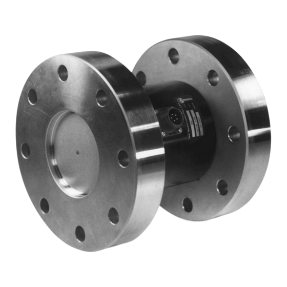
REACTION TORQUE SENSOR OPERATION MANUAL TABLE OF CONTENTS Section Page 1.0 Introduction 2.0 Safety Information 3.0 Mechanical Installation 4.0 Electrical Installation 5.0 Polarity 6.0 Shunt Calibration 7.0 Operation 8.0 Troubleshooting 9.0 Maintenance LIST OF ILLUSTRATIONS Figure Page 1. Flange Mount Reaction Torque Sensor 2. -
Page 7: Introduction
Gage Committee as revised in May 1960. wiring code is as follows: Reaction torque sensors manufactured by the Force- Torque Division of PCB are strain gage based measuring instruments suitable for a wide range of torque measurement applications. They are rigid structures with no moving parts and are typically mounted in a fixed position. -
Page 8: Safety Information
In addition, review data from manufacturers of fixtures and fasteners used in the sensors installation to determine if failure might occur due Figure 4 - Axis and Sense Nomenclature for PCB Reaction to these loads. Torque Sensors 3.0 MECHANICAL INSTALLATION The principal axis of a transducer is normally the axis. -
Page 9: Electrical Installation
2. Apply full-scale, N.I.S.T. traceable, utilized by PCB reaction torque sensors are typically mechanical input (or torque) to the transducer. calibrated using the shunt calibration technique. 3. Adjust the signal conditioner’s gain or span controls, as required, to obtain a full-scale... -
Page 10: Operation
Operation requires the connection of the sensor to a signal conditioner, then to a readout device (if signal conditioner does not have a display). Strain gage signal conditioners and cable assemblies are available from PCB. Operation with a Signal Conditioner The signal conditioner span and zero must be set before the torque sensor system can be used. -
Page 11: Troubleshooting
No output moments (extraneous loads), the errors due to them No power are present. PCB engineers can design the set-up to Loose or dirty connections eliminate or minimize these extraneous loads. Circuit opens or shorts However, if these extraneous loads are present, the Faulty or improper wiring... - Page 12 REACTION TORQUE SENSOR OPERATION MANUAL Caution should be observed to insure that liquids are not permitted to migrate into devices that are not hermetically sealed. Such devices should only be wiped with a damp cloth and never submerged or have liquids poured on them.
- Page 13 All specifications are at room temperature unless otherwise specified. Fax: 716-684-0987 In the interest of constant product improvement, we reserve the right to change specifications without notice. E-Mail: ltinfo@pcbloadtorque.com ® is a registered trademark of PCB Group, Inc. Web site: http://www.pcbloadtorque.com...
- Page 14 PCB Load & Torque Inc. claims proprietary rights in REVISIONS the information disclosed hereon. Neither it nor any reproduction thereof will be disclosed to others without DESCRIPTION the written consent of PCB Load and Torque Inc. REMOVE PIN OUT VIEW, UPDATE DIM'S - 02.23.18, PTE...
Need help?
Do you have a question about the 2303-02A and is the answer not in the manual?
Questions and answers