
Related Manuals for EROAD CoreHub Xtreme


Summary of Contents for EROAD CoreHub Xtreme
- Page 1 EROAD CoreHub Xtreme Install Guide (USA) - Carrier Technical support North 1-855-503-7 support@eroad.com America Australia 1800 437 support@eroad.com.au 0800 437 support@eroad.co.nz Zealand...
-
Page 2: Parts And Equipment
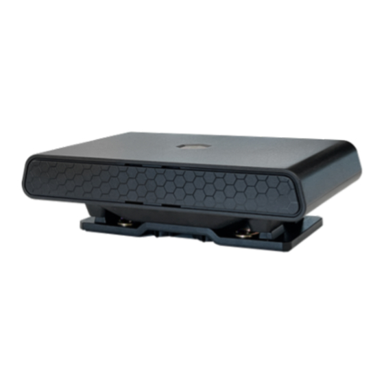
Parts and Equipment Included with the CoreHub Xtreme Install Kit: CoreHub Xtreme (the “unit”) Trailer and reefer Smart harness... -
Page 3: Required Tools
Remote Start Stop (RSS) switch harness (optional) External antenna Bracket Zip ties, screws Required tools • 10, 12, 13, 14, and 17 mm deep well sockets and wrenches • Diagonal flush cutters • Impact driver and 5/16ths bit for self-tapping screws •... - Page 4 A ladder is fine for heights up to 2 m (7 ft) but should not be considered safe for reaching the top of a reefer. Where possible, use a scissor-lift, forklift basket or similar stable, load-bearing platform. Pre-prep • Start the reefer to ensure it’s working with no console alarms.
-
Page 5: Mount The Unit
Mount the unit • Attach the unit to a flat surface half-way up the inside of the reefer, such as above the APX Control System display. • Use the holes in the mounting bracket to mark the drilling points on the reefer, attach the bracket accordingly, and mount the unit. - Page 6 Bracket...
- Page 8 Advance...
- Page 9 Vector 6500 Vector 8600 Mount the antenna Attach the antenna to the top of the reefer or the side front of the trailer. To function properly, it must directly see the sky.
- Page 10 (orange) power lines. • The main harness has connectors for reefer data (Satcomm1), fuel sensor, and the J1 jumper and/or optional RSS switch. • Use the provided zip ties to space the cables. Reefer data to CoreHub Xtreme harness...
- Page 11 Loop ties Attach the unit to J1 through the adapter Take the cap off the J1 and attach it to the adapter. Optional: Attach the unit to J1 with an optional RSS switch If you’re using the RSS switch for remote controlling the unit, you do not need the adapter.
- Page 12 • Tie the double-fuse holder near the APX display for future use. • Plug the switch cable into the J1 and also into the main harness. • Zip tie the old J1 jumper next to its connector for possible future use (in case it’s needed for emergency bypass).
- Page 13 Optional: Connect to trailer ABS module from the 7-way connector This step refers to using the optional trailer ABS harness (part number HHXTR7) if each axel’s odometer reading will be gathered for maintenance purposes. • The unit receives data from the 7-way connector.
- Page 14 Reefer on; look for a solid red light • Reconnect the battery. • Use the displayed table to troubleshoot the unit’s status. LED Color Flash Pattern Description Light Pink Solid Bootup Blue Solid Starting Services Green Solid/ Ignition Disconnected from Cloud Flashing/ Connecting to Ignition Off...
- Page 15 Use the Installer app to activate the unit and any wireless sensors • Scan the QR code to download or search for the Unit in Google Play or Apple’s App store. You can also find the QR code in the box the unit came in and on the back of the unit itself.
- Page 16 • Add sensors one at a time by scanning their QR codes. Each sensor has diagnostics. • Optionally, photo-document your work as described below. Photo verification Installers are encouraged to photo-document their work to assist in supporting work order documents. Any digital camera may be used for 2 or 3 images per site, but images must: •...
- Page 17 Once removed, fill holes with appropriate grommets, and weatherproof with silicone. Mount CoreHub Xtreme. Follow the steps detailed in this guide, with the following call- outs: If using the same TMU locations for the CoreHub Xtreme and its antenna: re-use the...
-
Page 18: Specifications
Be mindful of alterations to the reefer since the TMU’s installation: additional peripherals, special structures, etc., that may affect CoreHub Xtreme’s installation, its performance, or its structural integrity. If using a door sensor, a new wireless door sensor will need to be installed. (Wired door sensors are no longer supported.) -
Page 19: Health And Safety
Pinout Function Function RX2 (normally ADIO 5 debug) TX2 (normally ADIO 4 debug) RX1 (shared J1708) ADIO 3 TX1 (shared J1708) ADIO 2 CAN LOW ADIO 1 CAN HIGH 1708-/ CAN1 LOW 1-Wire 1708+/ CAN1 HIGH EXT 5/ 5 V SW -VIN/ Solar Panel - EX 12/ 12 V SW +VIN... - Page 20 This device is factory-sealed; tampering will void the warranty. Before installing EROAD equipment in a vehicle you must be, in Australia, an approved EROAD installer and, in New Zealand, an accredited EROAD installer. EROAD expects installers and contractors to understand and follow all relevant health and safety regulatory requirements.
- Page 21 While EROAD hardware is comprehensively tested against corrosion and ingress, devices are not invulnerable to water, fire or impact damage. Do not subject EROAD devices to extreme heat, high- pressure water force or other intense physical forces. Protect this device and other EROAD devices from extreme temperatures.
- Page 22 As EROAD is continuously improving its products, EROAD may make changes to this device at any time, which may not be reflected in this document. Please contact your nearest EROAD office if you require any further assistance.
Need help?
Do you have a question about the CoreHub Xtreme and is the answer not in the manual?
Questions and answers