
Related Manuals for EROAD CoreHub Xtreme


Summary of Contents for EROAD CoreHub Xtreme
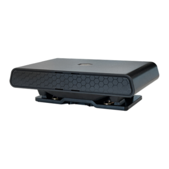
- Page 1 EROAD EROAD CoreHub Xtreme Install Guide Thermo King, AUS, NZL Technical support 1-855-503-7623 support@eroad.com 1800 437 623 support@eroad.com.au 0800 437 623 support@eroad.co.nz...
- Page 2 Parts & equipment CoreHub Xtreme (the ‘unit’) Trailer & reefer Smart harness External antenna...
- Page 3 Bracket Zip ties, screws...
-
Page 4: Required Tools
Required tools • Socket/ Spanner set • Side cutters • Impact driver and hex bits • 18/20ga butt splice crimping tool • Propane torch • Platform to safely reach the top of the reefer A ladder is fine for heights up to 2 m (7 ft) but should not be considered safe for reaching the top of a reefer. -
Page 5: Mount The Unit
Mount the unit • For SR4 units, mount the unit to the front of the trailer above the battery. Bracket... - Page 6 Precedent...
- Page 7 Legacy units • For legacy units (SR3 and before), mount the unit vertically on the upper half of the reefer next to the condenser inflow (above the display). • Keep the unit and cables away from hot or moving parts, and high voltage lines (usually colored orange).
-
Page 8: Mount The Antenna
Mount the antenna • Attach the antenna to the top of the reefer or the side front of the trailer. It should directly see the sky. Run the cables into the controller enclosure • Open the Precedent control compartment cover. Unscrew the cable cover to push the cables through to reach the power and data connections. - Page 9 Plug the unit into the reefer 3rd party port The unit’s harness has connectors for reefer data and fuel sensor. It plugs into the 3rd party communications port located inside the reefer controller module. Depending on the reefer type and readiness for telematics it may be necessary to do additional work to add this port to the reefer.
- Page 10 Reefer on; look for a solid red light Reconnect the battery. Use the displayed table to troubleshoot the unit’s status. Color Flash Desc Pink Solid Bootup Blue Solid Starting Services Green Solid /Ignition Disconnected from Cloud Flashing / Connecting to Cloud Ignition Off Solid /Ignition Connected to Cloud...
- Page 11 Use the Installer app to commission the unit & wireless sensors Scan the QR code to download or search for Unit in Google Play or Apple’s App Store. Log in to the app using your Core360 credentials. Turn on the reefer and verify that the unit’s status LED is solid red and that you are within 5 m of it.
- Page 12 Add sensors one at a time by scanning their QR codes. Each sensor has diagnostics. Photo verification Installers are encouraged to photo-document their work to assist in supporting work order documents. Any digital camera may be used for 2 or 3 images per site, but images must: •...
-
Page 13: Health And Safety
This device is factory-sealed; tampering will void the warranty. Before installing EROAD equipment in a vehicle you must be, in Australia, an approved EROAD installer and, in New Zealand, an accredited EROAD installer. EROAD expects installers and contractors to understand and follow all relevant health and safety regulatory requirements. - Page 14 While EROAD hardware is comprehensively tested against corrosion and ingress, devices are not invulnerable to water, fire or impact damage. Do not subject EROAD devices to extreme heat, high- pressure water force or other intense physical forces. Protect this device and other EROAD devices from extreme temperatures.
- Page 15 As EROAD is continuously improving its products, EROAD may make changes to this device at any time, which may not be reflected in this document. Please contact your nearest EROAD office if you require any further assistance.
- Page 16 Addendum Migrating from a TMU to Xtreme Unplug the TMU unit from all cabling. Take photos of the installation beyond this step. Record/confirm the serial number of the TMU before moving on. Except for the fuel sensor and its cabling, remove the antenna and any connected TMU- related hardware (harnesses, door sensors, etc).
-
Page 17: Specifications
Specifications Cellular 4G LTE WiFi 2.4 & 5 GHz 802.11 a/b/g/n, 150 Mbps Bluetooth Classic+BLE 4.2 GPS, BEIDOU, GLONASS, Galileo Power 12 V, 0.5 A 24 V, 0.25 A Int. Battery Lion rechargeable, or Li-hybrid Supercap (Optional) Dimensions 160 x 90 x 25 mm (6.3 x 3.5 x 1 250–400 g (0.5–0.8 lb) Temperature -40 —... - Page 18 Pinout Function Function RX2 (normally debug) 11 ADIO 5 TX2 (normally debug) 12 ADIO 4 RX1 (shared J1708) ADIO 3 TX1 (shared J1708) ADIO 2 CAN LOW ADIO 1 CAN HIGH 1708-/ CAN1 LOW 1-Wire 1708+/ CAN1 HIGH EXT 5/ 5 V SW -VIN/ Solar Panel - EX 12/ 12 V +VIN...
Need help?
Do you have a question about the CoreHub Xtreme and is the answer not in the manual?
Questions and answers