Table of Contents
Advertisement
Advertisement
Table of Contents

Related Manuals for ASROCK B650 PG LIGHTNING


Summary of Contents for ASROCK B650 PG LIGHTNING
- Page 2 Contact Information If you need to contact ASRock or want to know more about ASRock, you’re welcome to visit ASRock’s website at http://www.asrock.com; or you may contact your dealer for further information. For technical questions, please submit a support request form at https://event.asrock.com/tsd.asp...
-
Page 3: Table Of Contents
Package Contents Specifications Motherboard Layout I/O Panel Block Diagram 802.11axe Wi-Fi 6E Module and ASRock WiFi 2.4/5/6 GHz Antennas (For B650 PG Lightning WiFi) Chapter 2 Installation Installing the CPU Installing the CPU Fan and Heatsink Installing Memory Modules (DIMM) - Page 4 2.13 Smart Button 2.14 Post Status Checker 2.15 M.2 WiFi/BT Module Installation Guide (For B650 PG Lightning) 2.16 M.2 SSD Module Installation Guide (M2_1) 2.17 M.2 SSD Module Installation Guide (M2_2 and M2_3)
-
Page 5: Chapter 1 Introduction
If you require technical support related to this mother- board, please visit our website for specific information about the model you are using. You may find the latest VGA cards and CPU support list on ASRock’s website as well. ASRock website http://www.asrock.com. -
Page 6: Specifications
• Supports DDR5 ECC/non-ECC, un-buffered memory up to 7200+(OC)* • Max. capacity of system memory: 192GB • Supports Extreme Memory Profile (XMP) and EXTended Profiles for Overclocking (EXPO) memory modules * Please refer to Memory Support List on ASRock's website for more information. (http://www.asrock.com/) Expansion CPU: Slot • 1 x PCIe 4.0 x16 Slot (PCIE1), supports x16 mode*... - Page 7 B650 PG Lightning WiFi B650 PG Lightning • 2.5 Gigabit LAN 10/100/1000/2500 Mb/s • Dragon RTL8125BG • Supports Phantom Gaming LAN Software - Smart Auto Adjust Bandwidth Control - Visual User Friendly UI - Visual Network Usage Statistics - Optimized Default Setting for Game, Browser, and...
- Page 8 Rear Panel • 2 x Antenna Ports (For B650 PG Lightning WiFi) • 2 x Antenna Mounting Points (For B650 PG Lightning) • 1 x HDMI Port • 1 x USB 3.2 Gen2x2 Type-C Port (20 Gb/s) (ReDriver) • 7 x USB 3.2 Gen1 Ports (USB32_34 are Lightning Gaming...
- Page 9 • ErP/EuP ready (ErP/EuP ready power supply is required) * For detailed product information, please visit our website: http://www.asrock.com Please realize that there is a certain risk involved with overclocking, including adjusting the setting in the BIOS, applying Untied Overclocking Technology, or using third-party overclocking tools.
-
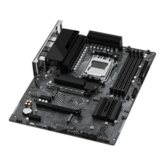
Page 10: Motherboard Layout
1.3 Motherboard Layout B650 PG Lightning WiFi: CPU_FAN2/WP CHA_FAN1 ATX12V1 ATX12V2 CPU_FAN1 USB 3.2 Gen1 T: USB32_1 B: USB32_2 USB 3.2 Gen1 Top: T: USB32_3 RJ-45 B: USB32_4 USB 3.2 Gen1 T: USB32_5 B: USB32_6 USB 3.2 Gen1 T:USB32_7 USB 3.2 Gen2x2... - Page 11 B650 PG Lightning WiFi B650 PG Lightning B650 PG Lightning : CPU_FAN2/WP CHA_FAN1 ATX12V1 ATX12V2 CPU_FAN1 USB 3.2 Gen1 T: USB32_1 B: USB32_2 USB 3.2 Gen1 Top: T: USB32_3 RJ-45 B: USB32_4 USB 3.2 Gen1 T: USB32_5 B: USB32_6 USB 3.2 Gen1 T:USB32_7 USB 3.2 Gen2x2...
- Page 12 No. Description ATX 12V Power Connector (ATX12V1) ATX 12V Power Connector (ATX12V2) CPU Fan Connector (CPU_FAN1) CPU/Water Pump Fan Connector (CPU_FAN2/WP) 2 x 288-pin DDR5 DIMM Slots (DDR5_A1, DDR5_B1) Post Status Checker (PSC) 2 x 288-pin DDR5 DIMM Slots (DDR5_A2, DDR5_B2) Chassis/Water Pump Fan Connector (CHA_FAN1/WP) Addressable LED Header (ADDR_LED2) ATX Power Connector (ATXPWR1)
-
Page 13: I/O Panel
B650 PG Lightning WiFi B650 PG Lightning 1.4 I/O Panel B650 PG Lightning WiFi: No. Description No. Description Antenna Ports USB 3.2 Gen1 Type-A Ports 2.5G LAN RJ-45 Port* (USB32_56) Line In (Light Blue)** USB 3.2 Gen1 Type-A Ports Front Speaker (Lime)**... - Page 14 B650 PG Lightning : No. Description No. Description 2.5G LAN RJ-45 Port* USB 3.2 Gen1 Type-A Ports Line In (Light Blue)** (USB32_56) Front Speaker (Lime)** USB 3.2 Gen1 Type-A Ports BIOS Flashback Button (USB32_34)*** Microphone (Pink)** USB 2.0 Ports (USB1234) USB 3.2 Gen1 Type-A Port...
- Page 15 B650 PG Lightning WiFi B650 PG Lightning *There are two LEDs on each LAN port. Please refer to the table below for the LAN port LED indications. ACT/LINK LED SPEED LED LAN Port Activity / Link LED Speed LED Status...
-
Page 16: Block Diagram
1.5 Block Diagram... -
Page 17: 802.11Axe Wi-Fi 6E Module And Asrock Wifi 2.4/5/6 Ghz Antennas (For B650 Pg Lightning Wifi)
B650 PG Lightning WiFi B650 PG Lightning 1.6 802.11axe Wi-Fi 6E Module and ASRock WiFi 2.4/5/6 GHz Antennas (For B650 PG Lightning WiFi) 802.11axe Wi-Fi 6E + BT Module This motherboard comes with an exclusive 802.11 a/b/g/n/ac/ax/axe Wi-Fi 6E + BT v5.2 module that offers support for 802.11 a/b/g/n/ac/ax/axe Wi-Fi 6E connectivity... - Page 18 WiFi Antennas Installation Guide Step 1 Prepare the WiFi 2.4/5/6 GHz Antennas that come with the package. Step 2 Connect the two WiFi 2.4/5/6 GHz Antennas to the antenna connectors. Turn the antenna clockwise until it is securely connected. Step 3 Set the WiFi 2.4/5/6 GHz Antenna as shown in the illustration.
-
Page 19: Chapter 2 Installation
B650 PG Lightning WiFi B650 PG Lightning Chapter 2 Installation This is an ATX form factor motherboard. Before you install the motherboard, study the configuration of your chassis to ensure that the motherboard fits into it. Pre-installation Precautions Take note of the following precautions before you install motherboard components or change any motherboard settings. -
Page 20: Installing The Cpu
2.1 Installing the CPU 1. Before you insert the 1718-Pin CPU into the socket, please check if the PnP cap is on the socket, if the CPU surface is unclean, or if there are any bent pins in the socket. Do not force to insert the CPU into the socket if above situation is found. - Page 21 B650 PG Lightning WiFi B650 PG Lightning Carefully place the CPU in as flat as possible. Do not drop it.
- Page 22 Make sure the CPU is aligned with the socket before locking it into place. Make sure the black cover plate is always in place until it pops off when closing the socket lever. Please save the cover if the processor is removed. The cover must be placed if you wish to return the motherboard for after service.
-
Page 23: Installing The Cpu Fan And Heatsink
B650 PG Lightning WiFi B650 PG Lightning 2.2 Installing the CPU Fan and Heatsink After you install the CPU into this motherboard, it is necessary to install a larger heatsink and cooling fan to dissipate heat. You also need to spray thermal grease between the CPU and the heatsink to improve heat dissipation. - Page 25 B650 PG Lightning WiFi B650 PG Lightning Installing the CPU Cooler (Type 2)
- Page 27 B650 PG Lightning WiFi B650 PG Lightning +12V *The illustrations shown here are for reference purposes only and may not exactly match the model you purchase.
- Page 28 Installing the CPU Cooler (Type 3)
- Page 29 B650 PG Lightning WiFi B650 PG Lightning...
- Page 31 +12V Please note that only one cable should be used at a time in this step. If you select RGB_LED1, please install ASRock utility "ASRock Polychrome SYNC". If you select USB connector, please install AMD utility "SR3 Settings Software". *The illustrations shown here are for reference purposes only and may not exactly match...
-
Page 32: Installing Memory Modules (Dimm)
2.3 Installing Memory Modules (DIMM) This motherboard provides four 288-pin DDR5 (Double Data Rate 5) DIMM slots, and supports Dual Channel Memory Technology. 1. For dual channel configuration, you always need to install identical (the same brand, speed, size and chip-type) DDR5 DIMM pairs. 2. - Page 33 B650 PG Lightning WiFi B650 PG Lightning...
-
Page 34: Connecting The Front Panel Header
2.4 Connecting the Front Panel Header Front Panel Wires System Panel Header Power SW (-) RESET SW (+) Power SW (+) RESET SW (-) Power LED (-) HDD LED (-) Power LED (+) HDD LED (+) PANEL1... -
Page 35: Installing The Motherboard
B650 PG Lightning WiFi B650 PG Lightning 2.5 Installing the Motherboard... -
Page 36: Installing Sata Drives
2.6 Installing SATA Drives Optical Drive SATA Drive SATA Data Cable... - Page 37 B650 PG Lightning WiFi B650 PG Lightning SATA Power Connector SATA Data Connector...
-
Page 38: Installing A Graphics Card
2.7 Installing a Graphics Card CLICK! - Page 39 B650 PG Lightning WiFi B650 PG Lightning Expansion Slots (PCIe Slots) There are 4 PCI Express slots on the motherboard. Before installing an expansion card, please make sure that the power supply is switched off or the power cord is unplugged. Please read the documentation of the expansion card and make necessary hardware settings for the card before you start the installation.
-
Page 40: Connecting Peripheral Devices
2.8 Connecting Peripheral Devices... -
Page 41: Connecting The Power Connectors
B650 PG Lightning WiFi B650 PG Lightning 2.9 Connecting the Power Connectors... -
Page 42: Power On
2.10 Power On... -
Page 43: Jumpers Setup
B650 PG Lightning WiFi B650 PG Lightning 2.11 Jumpers Setup The illustration shows how jumpers are setup. When the jumper cap is placed on the pins, the jumper is “Short”. If no jumper cap is placed on the pins, the jumper is “Open”. -
Page 44: Onboard Headers And Connectors
2.12 Onboard Headers and Connectors Onboard headers and connectors are NOT jumpers. Do NOT place jumper caps over these headers and connectors. Placing jumper caps over the headers and connectors will cause permanent damage to the motherboard. System Panel Header (9-pin PANEL1) (see p.6, 7, No. - Page 45 B650 PG Lightning WiFi B650 PG Lightning Power LED and Speaker Header (7-pin SPK_PLED1) (see p.6, 7, No. 18) Please connect the chassis power LED and the chassis speaker to this header. SPK_PLED1 SPEAKER DUMMY DUMMY PLED+ PLED+ PLED-...
- Page 46 Serial ATA3 Connectors Right Angle: (SATA3_1) (see p.6, 7, No. 15) (SATA3_2) (see p.6, 7, No. 16) Vertical: (SATA3_3) (see p.6, 7, No. 20) (SATA3_4) (see p.6, 7, No. 19) These four SATA3 connectors support SATA data cables for internal storage devices with up to 6.0 Gb/s data transfer rate.
- Page 47 B650 PG Lightning WiFi B650 PG Lightning USB 2.0 Headers (9-pin USB_5_6) (see p.6, 7, No. 22) (9-pin USB_7_8) (see p.6, 7, No. 21) There are two headers on this motherboard. Each USB 2.0 header can support two ports. USB_7_8...
- Page 48 USB 3.2 Gen1 Header (19-pin USB32_8_9) (see p.6, 7, No. 12) There is one header on this motherboard. This USB 3.2 Gen1 header can support two ports. USB32_8_9 Vbus Vbus Vbus IntA_PB_SSRX- IntA_PA_SSRX- IntA_PB_SSRX+ IntA_PA_SSRX+ IntA_PB_SSTX- IntA_PA_SSTX- IntA_PB_SSTX+ IntA_PA_SSTX+ IntA_PB_D- IntA_PA_D- IntA_PB_D+ IntA_PA_D+...
- Page 49 B650 PG Lightning WiFi B650 PG Lightning Front Panel Type C USB 3.2 Gen2 Header (20-pin USB32_TC2) (see p.6, 7, No. 11) There is one Front Panel Type C USB 3.2 Gen2 Header on this motherboard. This header is used for connecting a USB 3.2 Gen2 module for additional USB 3.2 Gen2 ports.
- Page 50 Front Panel Audio Header (9-pin HD_AUDIO1) (see p.6, 7, No. 28) This header is for connecting audio devices to the front audio panel. HD_AUDIO1 PRESENCE# MIC_RET OUT_RET OUT2_L J_SENSE OUT2_R MIC2_R MIC2_L High Definition Audio supports Jack Sensing, but the panel wire on the chassis must sup- port HDA to function correctly.
- Page 51 B650 PG Lightning WiFi B650 PG Lightning Chassis/Water Pump Fan Connectors (4-pin CHA_FAN1/WP) (see p.6, 7, No. 8) (4-pin CHA_FAN2/WP) (see p.6, 7, No. 13) (4-pin CHA_FAN3/WP) (see p.6, 7, No. 29) (4-pin CHA_FAN4/WP) (see p.6, 7, No. 24) This motherboard provides four 4-Pin water cooling chassis fan connectors. If you plan to connect a 3-Pin chassis water cooler fan, please connect it to Pin 1-3.
- Page 52 CPU Fan Connector (4-pin CPU_FAN1) (see p.6, 7, No. 3) This motherboard provides a 4-Pin CPU fan (Quiet Fan) connector. If you plan to connect a 3-Pin CPU fan, please connect it to Pin 1-3. CPU_FAN1 +12V CPU_F AN_SPEED FAN_SPEED_CONTROL...
- Page 53 B650 PG Lightning WiFi B650 PG Lightning CPU/Water Pump Fan Connector (4-pin CPU_FAN2/WP) (see p.6, 7, No. 4) This motherboard provides a 4-Pin water cooling CPU fan connector. If you plan to connect a 3-Pin CPU water cooler fan, please connect it to Pin 1-3.
- Page 54 ATX Power Connector (24-pin ATXPWR1) (see p.6, 7, No. 10) This motherboard provides a 24-pin ATX power connector. To use a 20-pin ATX power supply, please plug it along Pin 1 and Pin 13. ATXPWR1...
- Page 55 B650 PG Lightning WiFi B650 PG Lightning ATX 12V Power Connectors (8-pin ATX12V1) (see p.6, 7, No. 1) (8-pin ATX12V2) (see p.6, 7, No. 2) This motherboard provides two 8-pin ATX 12V power connectors. To use a 4-pin ATX power supply, please plug it along Pin 1 and Pin 5.
- Page 56 SPI TPM Header (13-pin SPI_TPM_J1) (see p.6, 7, No. 14) This connector supports SPI Trusted Platform Module (TPM) system, which can securely store keys, digital certificates, passwords, and data. A TPM system also helps enhance network security, protects digital identities, and ensures platform integrity. SPI_TPM_J1 SPI_DQ3 SPI_PWR...
- Page 57 B650 PG Lightning WiFi B650 PG Lightning RGB LED Header (4-pin RGB_LED1) (see p.6, 7, No. 27) This RGB header is used to connect RGB LED extension cable which allow users to choose from various LED lighting effects. Caution: Never install the RGB LED cable in the wrong orientation; otherwise, the cable may be damaged.
- Page 58 Addressable LED Headers (3-pin ADDR_LED1) (see p.6, 7, No. 26) (3-pin ADDR_LED2) (see p.6, 7, No. 9) (3-pin ADDR_LED3) (see p.6, 7, No. 25) These headers are used to connect Addressable LED extension cables which allow users to choose from various LED lighting effects. Caution: Never install the Addressable LED cable in the wrong orientation;...
- Page 59 B650 PG Lightning WiFi B650 PG Lightning 1. Never install the Addressable LED cable in the wrong orientation; otherwise, the cable may be damaged. 2. Before installing or removing your Addressable LED cable, please power off your system and unplug the power cord from the power supply. Failure to do so may cause damages to motherboard components.
- Page 60 2.13 Smart Button The motherboard has a smart button: BIOS Flashback Button, allowing users to flash the BIOS. BIOS Flashback Button (BIOS_FB1) (see p.9, No. 5 or p.10, No. 4) BIOS Flashback Button allows users to flash the BIOS. BIOS_FB1 USB BIOS Flashback port...
- Page 61 B650 PG Lightning WiFi B650 PG Lightning ASRock BIOS Flashback feature allows you to update BIOS without powering on the system, even without CPU. Before using the BIOS Flashback function, please suspend BitLocker and any encryption or security relying on the TPM. Make sure that you have already stored and backup-ed the recovery key.
- Page 62 2.14 Post Status Checker Post Status Checker (PSC) diagnoses the computer when users power on the machine. It emits a red light to indicate whether the CPU, memory, VGA or storage is dysfunctional. The lights go off if the four mentioned above are function- ing normally.
- Page 63 B650 PG Lightning WiFi B650 PG Lightning 2.15 M.2 WiFi/BT Module Installation Guide (For B650 PG Lightning) The M.2, also known as the Next Generation Form Factor (NGFF), is a small size and versatile card edge connector that aims to replace mPCIe and mSATA. The M.2 Socket (Key E) supports type 2230 WiFi/BT module.
- Page 64 Step 4 Tighten the screw with a screwdriver to secure the module into place. Please do not overtighten the screw as this might damage the module.
- Page 65 B650 PG Lightning WiFi B650 PG Lightning 2.16 M.2 SSD Module Installation Guide (M2_1) The M.2 is a small size and versatile card edge connector that aims to replace mPCIe and mSATA. The Blazing M.2 Socket (M2_1, Key M) supports type 2280 PCIe Gen5x4 (128 Gb/s) mode.
- Page 66 Step 3 Before installing a M.2 SSD module, please loosen the screws to remove the M.2 heatsink. *Please remove the protective films on the bottom side of the M.2 heatsink before you install a M.2 SSD module. Step 4 Align and gently insert the M.2 SSD module into the M.2 slot.
- Page 67 B650 PG Lightning WiFi B650 PG Lightning Step 5 Before securing the M.2 heatsink, make sure to align the notch on the SSD to the standoff on the motherboard if you use a Type 2280 SSD module; otherwise, the SSD module may be damaged.
- Page 68 M.2 connector (3). *Please do not overtighten the screw as this might damage the module and M.2 heatsink. For the latest updates of M.2 SSD module support list, please visit our website for details: http://www.asrock.com...
- Page 69 B650 PG Lightning WiFi B650 PG Lightning 2.17 M.2 SSD Module Installation Guide (M2_2 and M2_3) The M.2 is a small size and versatile card edge connector that aims to replace mPCIe and mSATA. The Hyper M.2 Socket (M2_2, Key M) supports type 2280 PCIe Gen4x4 (64 Gb/s) mode.
- Page 70 Tighten the screw with a screwdriver to secure the module into place. Please do not overtighten the screw as this might damage the module. NUT2 NUT1 For the latest updates of M.2 SSD module support list, please visit our website for details: http://www.asrock.com...
- Page 71 (including damages for loss of profits, loss of business, loss of data, interruption of business and the like), even if ASRock has been advised of the possibility of such damages arising from any defect or error in the documentation or product.
- Page 72 If you require assistance please call ASRock Tel : +886-2-28965588 ext.123 (Standard International call charges apply)
- Page 73 ASRock follows the green design concept to design and manufacture our products, and makes sure that each stage of the product life cycle of ASRock product is in line with global environmental regulations. In addition, ASRock disclose the relevant information based on regulation requirements.
- Page 74 Operations in the 5.15-5.35/6GHz band are restricted to indoor usage only. Radio transmit power per transceiver type Function Frequency Maximum Output Power (EIRP) 2400-2483.5 MHz 18.5 + / -1.5 dbm 5150-5250 MHz 21.5 + / -1.5 dbm 18.5 + / -1.5 dbm (no TPC) 5250-5350 MHz 21.5 + / -1.5 dbm (TPC) WiFi...
Need help?
Do you have a question about the B650 PG LIGHTNING and is the answer not in the manual?
Questions and answers