Advertisement
GENERAL SAFETY RULES

Read and understand all instructions. Failure to follow all instructions listed below, may result in electric shock, fire and/or serious personal injury.
READ ALL INSTRUCTIONS
- KNOW YOUR POWER TOOL. Read the operator's manual carefully. Learn the applications and limitations as well as the specific potential hazards related to this tool.
- GUARD AGAINST ELECTRICAL SHOCK BY PREVENTING BODY CONTACT WITH GROUNDED SURFACES. For example: pipes, radiators, ranges, refrigerator enclosures, etc.
- KEEP GUARDS IN PLACE and in good working order.
- REMOVE ADJUSTING KEYS AND WRENCHES. Form habit of checking to see that keys and adjusting wrenches are removed from tool before turning it on.
- KEEP WORK AREA CLEAN. Cluttered areas and benches invite accidents. DO NOT leave tools or pieces of wood on the tool while it is in operation.
- DO NOT USE IN DANGEROUS ENVIRONMENTS. Do not use power tools in damp or wet locations or expose to rain. Keep the work area well lit.
- KEEP CHILDREN AND VISITORS AWAY. All visitors should wear safety glasses and be kept a safe distance from work area. Do not let visitors contact tool or extension cord while operating.
- MAKE WORKSHOP CHILDPROOF with padlocks, master switches, or by removing starter keys.
- DON'T FORCE THE TOOL. It will do the job better and safer at the feed rate for which it was designed.
- USE THE RIGHT TOOL. Do not force the tool or attachment to do a job for which it was not designed.
- USE THE PROPER EXTENSION CORD. Make sure your extension cord is in good condition. Use only a cord heavy enough to carry the current your product will draw. An undersized cord will cause a drop in line voltage resulting in loss of power and overheating. A wire gauge size (A.W.G.) of at least 16 is recommended for an extension cord 50 feet or less in length. If in doubt, use the next heavier gauge. The smaller the gauge number, the heavier the cord.
- DRESS PROPERLY. Do not wear loose clothing, neckties or jewelry. They can get caught and draw you into moving parts. Also wear protective hair covering to contain long hair.
- ALWAYS WEAR EYE PROTECTION WITH SIDE SHIELDS WHICH IS MARKED TO COMPLY WITH ANSI Z87.1 WHEN USING THIS P RODUCT.
- SECURE WORK. Use clamps or a vise to hold work when practical, it is safer than using your hand and frees both hands to operate the tool.
- DO NOT OVERREACH. Keep proper footing and balance at all times.
- MAINTAIN TOOLS WITH CARE. Keep tools sharp and clean for better and safer performance. Follow instructions for lubricating and changing accessories.
- DISCONNECT TOOLS. When not in use, before servicing, or when changing attachments, blades, bits, cutters, etc., all tools should be disconnected from power source.
- AVOID ACCIDENTAL STARTING. Be sure switch is off when plugging in any tool.
- USE RECOMMENDED ACCESSORIES. Consult the operator's manual for recommended accessories. The use of improper accessories may result in injury.
- NEVER STAND ON TOOL. Serious injury could occur if the tool is tipped.
- CHECK DAMAGED PARTS. Before further use of the tool, a guard or other part that is damaged should be carefully checked to determine that it will operate properly and perform its intended function. Check for alignment of moving parts, binding of moving parts, breakage of parts, mounting and any other conditions that may affect its operation. A guard or other part that is damaged must be properly repaired or replaced by an authorized service center to avoid risk of personal injury.
- USE THE RIGHT DIRECTION OF FEED. Feed work into a blade, cutter, or sanding spindle against the direction or rotation of the blade, cutter, or sanding spindle only.
- NEVER LEAVE TOOL RUNNING UNATTENDED. TURN THE POWER OFF. Don't leave tool until it comes to a complete stop.
- PROTECT YOUR LUNGS. Wear a face or dust mask if the cutting operation is dusty.
- PROTECT YOUR HEARING. Wear hearing protection during extended periods of operation.
- DO NOT ABUSE CORD. Never carry tool by the cord or yank it to disconnect from receptacle. Keep cord from heat, oil, and sharp edges.
- USE OUTDOOR EXTENSION CORDS. When tool is used outdoors, use only extension cords with approved ground connection that are intended for use outdoors and so marked.
- STAY ALERT AND EXERCISE CONTROL. Watch what you are doing and use common sense. Do not operate tool when you are tired. Do not rush.
- DO NOT USE TOOL IF SWITCH DOES NOT TURN IT ON AND OFF. Have defective switches replaced by an authorized service center.
- ALWAYS TURN SWITCH OFF before disconnecting it to avoid accidental starting.
- NEVER USE IN AN EXPLOSIVE ATMOSPHERE. Normal sparking of the motor could ignite fumes.
- INSPECT TOOL CORDS PERIODICALLY. If damaged, have repaired by a qualified service technician at an authorized service facility. The conductor with insulation having an outer surface that is green with or without yellow stripes is the equipment-grounding conductor. If repair or replacement of the electric cord or plug is necessary, do not connect the equipment-grounding conductor to a live terminal. Repair or replace a damaged or worn cord immediately. Stay constantly aware of cord location and keep it well away from the rotating blade.
- INSPECT EXTENSION CORDS PERIODICALLY and replace if damaged.
- GROUND ALL TOOLS. If tool is equipped with 3-prong plug, it should be plugged into a 3-hole electrical receptacle.
- USE ONLY CORRECT ELECTRICAL DEVICES: 3-wire extension cords that have 3-prong grounding plugs and 3-pole receptacles that accept the tool's plug.
- KEEP TOOL DRY, CLEAN, AND FREE FROM OIL AND GREASE. Always use a clean cloth when cleaning. Never use brake fluids, gasoline, petroleum-based products or any solvents to clean tool.
- NEVER START A TOOL WHEN ANY ROTATING COMPONENT IS IN CONTACT WITH THE WORKPIECE.
- DO NOT OPERATE A TOOL WHILE UNDER THE INFLUENCE OF DRUGS, ALCOHOL OR ANY MEDICATION.
- WHEN SERVICING use only identical replacement parts. Use of any other parts may create a hazard or cause product damage.
- USE ONLY RECOMMENDED ACCESSORIES listed in this manual or addendums. Use of accessories that are not listed may cause the risk of personal injury. Instructions for safe use of accessories are included with the accessory.
SPECIFIC SAFETY RULES
- KEEP BITS CLEAN AND SHARP. Sharp bits minimize stalling. Dirty and dull bits may cause misalignment of the material and possible operator injury.
- KEEP HANDS AWAY FROM WORK AREA. Keep hands away from the bit. Restrain any loose clothing, jewelry, long hair, etc., that may become entangled in the bit.
- ALWAYS CLAMP WORKPIECE OR BRACE AGAINST COLUMN TO PREVENT ROTATION. Never use your hand to hold the object while drilling.
- USE RECOMMENDED SPEED FOR DRILL ACCESSORY AND WORKPIECE MATERIAL.
- BE SURE DRILL BIT OR CUTTING TOOL IS SECURELY LOCKED IN THE CHUCK.
- BE SURE CHUCK KEY IS REMOVED from the chuck before connecting to power source or turning power ON.
- ADJUST THE TABLE OR DEPTH STOP TO AVOID DRILLING INTO THE TABLE. Shut off the power, remove the drill bit, and clean the table before leaving machine.
- AVOID DIRECT EYE EXPOSURE when using the laser guide.
- ALWAYS ENSURE THE LASER BEAM IS AIMED AT A SURFACE WITH OUT REFLECTIVE PROPERTIES. Shiny reflective materials are not suitable for laser use.
- NEVER PLACE YOUR FINGERS IN A POSITION WHERE THEY COULD CONTACT THE DRILL or other cutting tool if the workpiece should unexpectedly shift.
- NEVER PERFORM ANY OPERATION by moving the head or table with respect to one another. Do not turn the motor switch ON or start any operation before checking that the head and table support lock handle is clamped tight to column and head and table support collars are correctly positioned.
- BEFORE ENGAGING THE POWER SWITCH, MAKE SURE THE BELT GUARD IS DOWN AND THE CHUCK IS INSTALLED PROPERLY.
- LOCK THE MOTOR SWITCH OFF WHEN LEAVING THE DRILL PRESS. Do not perform layout, assembly, or set-up work on the table while the cutting tool is rotating, switched on, or connected to a power source.
- IF THE POWER SUPPLY CORD IS DAMAGED, it must be replaced only by the manufacturer or by an authorized service center to avoid risk.
- SAVE THESE INSTRUCTIONS. Refer to them frequently and use to instruct other users. If you loan someone this tool, loan them these instructions also.
SYMBOLS
The following signal words and meanings are intended to explain the levels of risk associated with this product.
| SYMBOL | SIGNAL | MEANING |
 | DANGER: | Indicates a hazardous situation, which, if not avoided, will result in death or serious injury. |
| | WARNING: | Indicates a hazardous situation, which, if not avoided, could result in death or serious injury. |
 | CAUTION: | Indicates a hazardous situation, that, if not avoided, may result in minor or moderate injury. |
 | NOTICE: | (Without Safety Alert Symbol) Indicates information considered important, but not related to a potential injury (e.g. messages relating to property damage). |
Some of the following symbols may be used on this tool. Please study them and learn their meaning. Proper interpretation of these symbols will allow you to operate the tool better and safer.
| SYMBOL | NAME | DESIGNATION/EXPLANATION |
| | Safety Alert | Indicates a potential personal injury hazard. |
 | Read Operator's Manual | To reduce the risk of injury, user must read and understand operator's manual before using this product. |
 | Eye Protection | Always wear eye protection with side shields marked to comply with ANSI Z87.1. |
 | Wet Conditions Alert | Do not expose to rain or use in damp locations. |
| V | Volts | Voltage |
| A | Amperes | Current |
| Hz | Hertz | Frequency (cycles per second) |
| W | Watt | Power |
| min | Minutes | Time |
 | Alternating Current | Type of current |
| no | No Load Speed | Rotational speed, at no load |
| .../min | Per Minute | Revolutions, strokes, surface speed, orbits etc., per minute |
ELECTRICAL
EXTENSION CORDS
Use only 3-wire extension cords that have 3-prong grounding plugs and 3-pole receptacles that accept the tool's plug. When using a power tool at a considerable distance from the power source, use an extension cord heavy enough to carry the current that the tool will draw. An undersized extension cord will cause a drop in line voltage, resulting in a loss of power and causing the motor to overheat. Use the chart provided below to determine the minimum wire size required in an extension cord. Only round jacketed cords listed by Underwriter's Laboratories (UL) should be used.
**Ampere rating (on tool faceplate)
| Cord Length | Wire Size (A.W.G.) | |||||
| 0-2.0 | 2.1-3.4 | 3.5-5.0 | 5.1-7.0 | 7.1-12.0 | 12.1-16.0 | |
| 25' | 16 | 16 | 16 | 16 | 14 | 14 |
| 50' | 16 | 16 | 16 | 14 | 14 | 12 |
| 100' | 16 | 16 | 14 | 12 | 10 | — |
**Used on 12 gauge - 20 amp circuit.
NOTE: AWG = American Wire Gauge
When working with the tool outdoors, use an extension cord that is designed for outside use. This is indicated by the letters "W-A" or "W" on the cord's jacket.
Before using an extension cord, inspect it for loose or exposed wires and cut or worn insulation.
Keep the extension cord clear of the working area. Position the cord so that it will not get caught on lumber, tools or other obstructions while you are working with a power tool. Failure to do so can result in serious personal injury.
Check extension cords before each use. If damaged replace immediately. Never use tool with a damaged cord since touching the damaged area could cause electrical shock resulting in serious injury.
ELECTRICAL CONNECTION
This tool is powered by a precision built electric motor. It should be connected to a power supply that is 120 volts, AC only (normal household current), 60 Hz. Do not operate this tool on direct current (DC). A substantial voltage drop will cause a loss of power and the motor will overheat. If the tool does not operate when plugged into an outlet, double check the power supply.
SPEED AND WIRING
The no-load speed of this tool is approximately 3,050 rpm. This speed is not constant and decreases under a load or with lower voltage. For voltage, the wiring in a shop is as important as the motor's horsepower rating. A line intended only for lights cannot properly carry a power tool motor. Wire that is heavy enough for a short distance will be too light for a greater distance. A line that can support one power tool may not be able to support two or three tools.
GROUNDING INSTRUCTIONS

- Grounding pin
- 120V grounded outlet
In the event of a malfunction or breakdown, grounding provides a path of least resistance for electric current to reduce the risk of electric shock. This tool is equipped with an electric cord having an equipment-grounding conductor and a grounding plug. The plug must be plugged into a matching outlet that is properly installed and grounded in accordance with all local codes and ordinances.
Do not modify the plug provided. If it will not fit the outlet, have the proper outlet installed by a qualified electrician. Improper connection of the equipment-grounding conductor can result in a risk of electric shock. The conductor with insulation having an outer surface that is green with or without yellow stripes is the equipment-grounding conductor. If repair or replacement of the electric cord or plug is necessary, do not connect the equipment-grounding conductor to a live terminal.
Check with a qualified electrician or service personnel if the grounding instructions are not completely understood, or if in doubt as to whether the tool is properly grounded. Repair or replace a damaged or worn cord immediately.
This tool is intended for use on a circuit that has an outlet like the one shown in Figure 1. It also has a grounding pin like the one shown.
GLOSSARY OF TERMS
Anti-Kickback Pawls (radial arm and table saws)
A device which, when properly installed and maintained, is designed to stop the workpiece from being kicked back toward the front of the saw during a ripping operation.
Arbor
The shaft on which a blade or cutting tool is mounted.
Bevel Cut
A cutting operation made with the blade at any angle other than 90° to the table surface.
Chamfer
A cut removing a wedge from a block so the end (or part of the end) is angled rather than at 90°.
Compound Cut
A cross cut made with both a miter and a bevel angle.
Cross Cut
A cutting or shaping operation made across the grain or the width of the workpiece.
Cutter Head (planers and jointer planers)
A rotating cutterhead with adjustable blades or knives. The blades or knives remove material from the workpiece.
Dado Cut (table saws and compound sliding miter saws)
A non-through cut which produces a square, 3-sided notch or trough in the workpiece.
Featherboard (table saws)
A device used to help control the workpiece by guiding it securely against the table or fence during any ripping operation.
FPM or SPM
Feet per minute (or strokes per minute), used in reference to blade movement.
Freehand
Performing a cut without the workpiece being guided by a fence, miter fence, or other aids.
Gum
A sticky, sap-based residue from wood products.
Heel
Alignment of the blade to the fence.
Kerf
The material removed by the blade in a through cut or the slot produced by the blade in a non-through or partial cut.
Kickback
A hazard that can occur when the blade binds or stalls, throwing the workpiece in the direction of the spinning blade.
Miter Cut
A cutting operation made with the workpiece at any angle to the blade other than 90°.
Non-Through Cuts (table saws and compound sliding miter saws)
Any cutting operation where the blade does not extend completely through the thickness of the workpiece. This is a cut where the blade will not cut the workpiece into two pieces.
Pilot Hole (drill presses and scroll saws)
A small hole drilled in a workpiece that serves as a guide for drilling large holes accurately or for insertion of a scroll saw blade.
Push Blocks (jointer planers)
Device used to feed the workpiece over the jointer planer cutterhead during any operation. This aid helps keep the operator's hands well away from the cutterhead.
Push Blocks and Push Sticks (table saws)
Devices used to feed the workpiece through the saw blade during cutting operations. When making a narrow rip cut without a jig or similar cutting aid, always use a push stick (not a push block). A push block can be used for narrow ripping operations, if a jig or similar cutting aid is used. These aids help keep the operator's hands well away from the blade.
Rabbet
A non-through cut positioned on the end or edge of the workpiece which produces a square, two-sided notch or trough in the workpiece.
Resaw (table saws and band saws)
A cutting operation to reduce the thickness of the workpiece to make thinner pieces.
Resin
A sticky, sap-based substance that has hardened.
Revolutions Per Minute (RPM)
The number of turns completed by a spinning object in one minute.
Ripping or Rip Cut (table saws)
A cutting operation along the length of the workpiece and typically in the direction of the grain.
Riving Knife/Spreader/Splitter (table saws)
A metal piece, slightly thinner than the blade, which helps keep the kerf open and also helps to prevent kickback.
Saw Blade Path
The area over, under, behind, or in front of the blade. As it applies to the workpiece, that area which will be or has been cut by the blade.
Snipe (planers)
Depression made at either end of a workpiece by cutter blades when the workpiece is not properly supported.
Taper Cut
A cut where the material being cut has a different width at the beginning of the cut from the end.
Through Sawing
Any cutting operation where the blade extends completely through the thickness of the workpiece. This type of cut will separate a single workpiece into two pieces.
Workpiece or Material
The item on which the operation is being done.
Worktable
Surface where the workpiece rests while performing a cutting, drilling, planing, or sanding operation.
FEATURES
PRODUCT SPECIFICATIONS
Chuck: 1/2 in.
Input: 120 Volt, 60Hz, AC Only, 6.2 Amps
Motor: 1/4 HP Induction
No Load Speed: 630-3, 050 r/min. (RPM)
Swing: 10 in.
Spindle Travel: 2 in.
Table Size: 7-5/8 in. x 6-1/2 in.
Table Movement: 45° bevel, 360° swivel
Overall Height: 29 in.
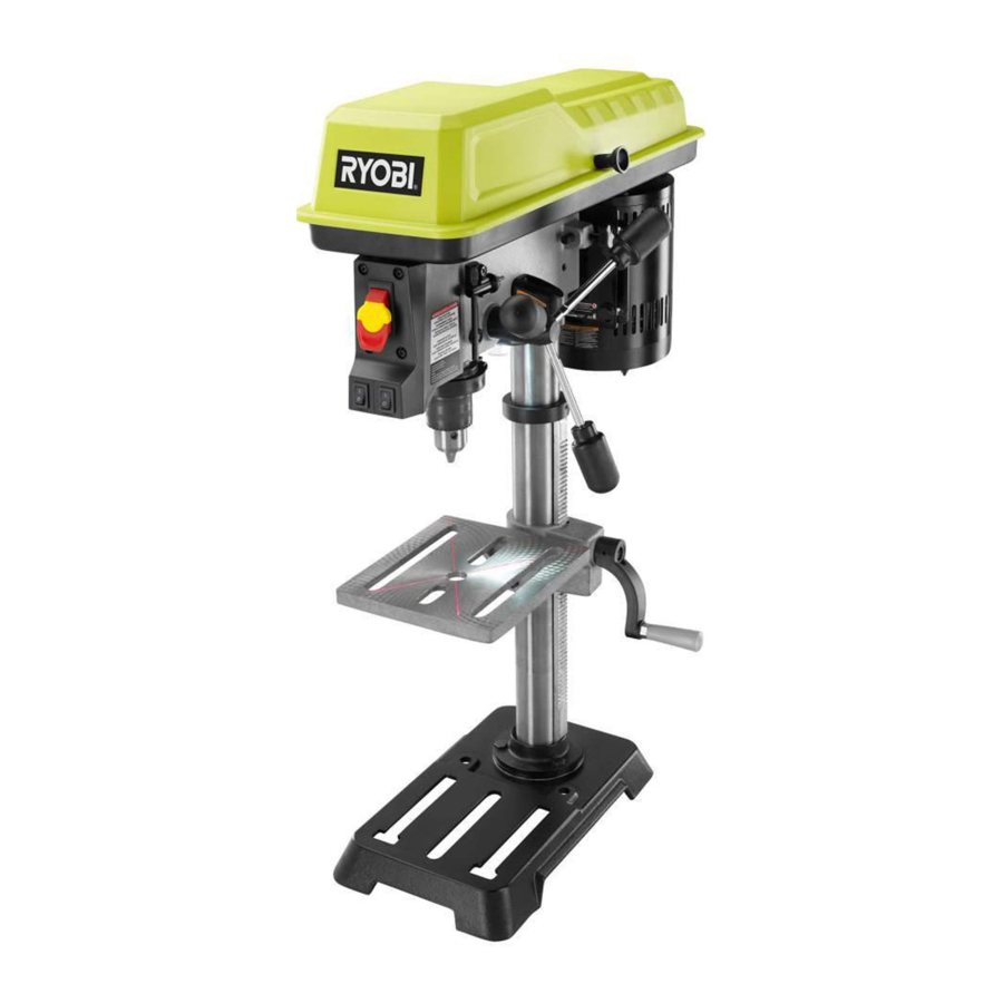
KNOW YOUR DRILL PRESS

- LED worklight
- Laser
- Table
- Chuck
- Power switch
- Switch key
- Worklight on/off switch
- Laser on/off switch
- Depth gauge
- Depth stop locking collar
- Feed handle
- Table adjustment handle
- Base
- Bevel scale
The safe use of this product requires an understanding of the information on the tool and in this operator's manual as well as a knowledge of the project you are attempting. Before use of this product, familiarize yourself with all operating features and safety rules.
BEVEL SCALE
The bevel scale indicates the degree the table is tilted.
CHUCK
Your drill press features a standard 3-jaw type chuck with a self-ejecting chuck key, which prevents accidentally starting the drill press with the key still engaged in the chuck.
EXACTLINE™ LASER
The Exactline™ laser makes accurate, precision drilling simple and easy.
DEPTH GAUGE
A depth gauge is located between the pulley housing and feed handles to aid in drilling at desired depths.
DEPTH STOP
The adjustable locking depth stop permits accurate depth measurement and repetitive drilling.
FEED HANDLES
Feed handles raise and lower the chuck and bit during the drilling operation.
MOTOR
Your drill press is equipped with an industrial duty induction motor for long-lasting, smooth performance.
SPINDLE SPEED
Five different spindle speeds allow you to drill a wide variety of material including wood, plastic, and metal.
TABLE
The table of your drill press rotates 3600 and bevels up to 450 for angle drilling.
WORKLIGHT
The integrated LED worklight can be used to help illuminate the work area.
ASSEMBLY
UNPACKING
This product requires assembly.
- Carefully remove the tool and any accessories from the box. Place it on a level work surface.
NOTE: This tool is heavy. To avoid back injury, lift with your legs, not your back, and get help when needed.
Do not use this product if any parts on the Loose Parts List are already assembled to your product when you unpack it. Parts on this list are not assembled to the product by the manufacturer and require customer installation. Use of a product that may have been improperly assembled could result in serious personal injury.
- Inspect the tool carefully to make sure no breakage or damage occurred during shipping.
- Do not discard the packing material until you have carefully inspected the tool, identified all loose parts, and satisfactorily operated the tool.
- If any parts are damaged or missing, please call 1-800-525-2579 for assistance.
If any parts are damaged or missing, do not operate this tool until the parts are replaced. Use of this product with damaged or missing parts could result in serious personal injury.
Do not attempt to modify this tool or create accessories not recommended for use with this tool. Any such alteration or modification is misuse and could result in a hazardous condition leading to possible serious personal injury.
Do not connect to power supply until assembly is complete. Failure to comply could result in accidental starting and possible serious personal injury.
TOOLS NEEDED
The following tools (not included or drawn to scale) are needed for assembly:
- Mallet or hammer
- Adjustable wrench
- Phillips screwdriver
LOOSE PARTS LIST

The following items are included with the tool:
- Depth gauge: 1
- Chuck key: 1
- Table assembly: 1
- Hex key: 1
- Feed handles: 3
- Hex bolts: 3
- Base: 1
- Column collar: 1
- Table adjustment handle: 1
- Worm gear: 1
- Chuck: 1
- Table lock handle: 1
- Head assembly: 1
ATTACHING COLUMN ASSEMBLY TO BASE

- Column assembly
- Hex bolt
- Base
- Place the base on a flat surface. Align screw holes in the column assembly with screw holes in the base.
- Place a hex bolt in each hole and tighten using an adjustable wrench.
INSTALLING TABLE ASSEMBLY

- Worm gear
- Table lock handle
- D-shaft
- Threaded hole
- Slot

- Gear rack
- Table assembly

- Set screw
- Table assembly
- Base collar
- Gear rack
- Column collar

- Head assembly
- Set screw
- Hex key
- Loosen the set screw in the column collar. Remove the column collar and gear rack from the column and set aside.
- Clean the spindle with a degreaser before installing the chuck into the head.
- Locate the worm gear and feed the D-shaft through the hole in the table assembly.
- Install table adjustment handle over the end of the D-shaft so that the flat side of the shaft aligns with the set screw. Tighten the set screw using the hex key.
- Feed the gear rack through the slot in the table assembly so that the teeth are facing out and the longer smooth end faces up. The worm gear should engage the gear rack.
- Using both hands, slide the entire table assembly and gear rack onto the column until the bottom of the gear rack is positioned in the base collar and against the column.
- Slide the column collar, bevel-side down, over the column until the beveled side engages the beveled end of the gear rack. Tighten the set screw in the collar using the hex key. Do not overtighten.
![warning]() NOTE: You should be able to move the table from side to side.
NOTE: You should be able to move the table from side to side. - Locate the table lock handle. Insert it into the threaded hole at the rear of the table assembly and tighten by hand.
INSTALLING CHUCK, HEAD ASSEMBLY, AND FEED HANDLES

- Mallet
- Scrap wood
- Chuck

- Feed handle
- Place the head assembly upside down on a level, flat surface.
- Position chuck on spindle. Chuck should be fully opened to avoid damaging jaws.
- Using a piece of scrap wood to protect the chuck, firmly tap the chuck into place using a mallet or hammer.
- Position the head assembly onto the column with the chuck positioned over the table.
![warning]() NOTE: This head assembly is heavy. Get help when needed.
NOTE: This head assembly is heavy. Get help when needed. - Slide the head assembly down as far as it will go. Align the table assembly with the base and then tighten the two head set screws with the hex key.
- Attach the three feed handles by screwing them into the threaded holes in the hub.
MOUNTING THE DRILL PRESS

- Mounting bolts
- Base
If the drill press is to be used in a permanent location, secure it to a workbench or other stable surface.
If the drill press is to be used as a portable tool, fasten it permanently to a mounting board that can easily be clamped to a workbench or other stable surface. The mounting board should be of sufficient size to avoid tipping while drill press is in use. Any good grade plywood or chipboard with a 3/4 in. thickness is recommended.
- Mark holes on surface where drill press is to be mounted using holes in drill press base as a template for hole pattern.
- Drill holes through mounting surface.
- Place drill press on mounting surface, aligning holes in the base with holes drilled in the mounting surface.
- Insert bolts (not included) and tighten securely with lock washers and hex nuts (not included).
- If lag bolts are used, make sure they are long enough to go through holes in drill press base and material the drill press is being mounted to. If machine bolts are used, make sure bolts are long enough to go through holes in drill press, the material being mounted to, and the lock washers and hex nuts.
![warning]() NOTE: All bolts should be inserted from the top. Install the lock washers and hex nuts from the underside of the workbench.
NOTE: All bolts should be inserted from the top. Install the lock washers and hex nuts from the underside of the workbench.
Once the drill press is securely mounted on a sturdy surface:
- Check for vibration when the motor is switched ON.
- Adjust and retighten the mounting hardware as n ecessary.
- Check the table assembly to assure smooth movement up and down the column.
- Check to assure that the spindle shaft moves s moothly.
Laser radiation. Avoid direct eye contact with light source.
Use of controls or adjustments or performance of procedures other than those specified herein could result in hazardous radiation exposure.
CHECKING/ADJUSTING LASER ALIGNMENT

- Laser housing
- Set screw
- Laser adjustment knob
Check the laser alignment to ensure the intersection of the laser lines is precisely at the spot where the drill bit meets the workpiece. If it is not, the laser lines should be adjusted using the laser adjustment knobs located on opposite sides of the head assembly.
- Mark an "X" on a piece of scrap wood.
- Insert a small drill bit into the chuck and align its tip to the intersection of the lines of the "X".
- Secure the board to the table.
- Turn on the laser and verify the laser lines align with the "X" on the workpiece.
- If the laser lines do not align, loosen the set screws on each of the laser housings with a hex key and rotate the laser adjustment knobs until the lines meet in the center of the "X". Retighten the set screws to secure.
OPERATION
Do not allow familiarity with tools to make you careless. Remember that a careless fraction of a second is sufficient to inflict serious injury.
Always wear eye protection with side shields marked to comply with ANSI Z87.1. Failure to do so could result in objects being thrown into your eyes, resulting in possible serious injury.
Do not use any attachments or accessories not recommended by the manufacturer of this tool. The use of attachments or accessories not recommended can result in serious personal injury.
To prevent the workpiece or the backup material from being torn from your hand while drilling, position them against the left side of the column. If the workpiece or the backup material are not long enough to reach the column, clamp them to the table. Failure to do this could result in personal injury.
APPLICATIONS
You may use this tool for the purposes listed below:
- Drilling in wood
- Drilling in ceramics, plastics, fiberglass, and laminates
- Drilling in metals
POWER SWITCH

- Power on
- Power off
- Switch key
The drill press is equipped with a power switch that has a built-in locking feature. This feature is intended to prevent unauthorized and possible hazardous use by children and others.
To turn the drill press on:
- With the switch key inserted into the switch, lift the switch to turn ON ( l ).
To turn the drill press off:
- With the switch key inserted into the switch, push the switch down to turn OFF ( O ).
To LOCK the drill press:
- Place the switch in the OFF ( O ) position.
- Remove the switch key from the switch and store in a secure location.
ALWAYS remove the switch key when the tool is not in use and keep it in a safe place. In the event of a power failure, turn the switch OFF ( O ) and remove the key. This action will prevent the tool from accidentally starting when power returns.
Always make sure the workpiece is not in contact with the bit before operating the switch to start the tool. Failure to heed this warning may cause the workpiece to be kicked back toward the operator and result in serious personal injury.
SELF-EJECTING CHUCK KEY

- Chuck key
- Key hole
The self-ejecting chuck key ensures the chuck key is removed from the chuck before the drill press is turned on.
In order to loosen or tighten the chuck using the chuck key, push the key into the key hole located on the chuck. Rotate the key clockwise to tighten the chuck or counterclockwise to loosen the chuck.
Use only the self-ejecting chuck key provided. Always remove chuck key. Failure to heed this warning could result in serious personal injury.
TABLE ROTATION

- Table lock handle
- Table assembly
The table can be rotated out of the way when drilling large objects.
- Loosen the table lock handle.
- Rotate the table to the desired position.
- Retighten the table lock handle.
INSTALLING AND REMOVING BITS

- Unplug the drill press.
- Open or close the chuck jaws to a point where the opening is slightly larger than the bit size you intend to use.
- Insert drill bit into the chuck the full length of the jaws.
Do not insert drill bit into chuck jaws and tighten. This could cause drill bit to be thrown from the drill press, resulting in possible serious personal injury or damage to the chuck.
- Tighten chuck jaws securely using chuck key provided. Do not use a wrench to tighten or loosen chuck jaws.
- Remove chuck key.
- To remove the drill bit, reverse the steps listed above.
DRILLING

- Clamp
- Workpiece
- Scrap wood
- Using a clamping device, secure the workpiece to the worktable. To protect the top surface of the workpiece, use a piece of scrap wood between the clamping device and the workpiece.
- Select the proper drill bit based on the hole size desired. For large holes, drill a pilot hole first, using a smaller diameter bit.
- Select and set the recommended spindle speed. Refer to "Changing Speeds" in the Adjustments section of this manual.
- Set table assembly to desired height. Refer to "Adjusting Table" Height in the Adjustments section.
- If desired, set feed shaft at desired spindle depth. Refer to "Adjusting Depth Gauge" in the Adjustments section.
- Make sure the work table is free of all loose objects and the bit is not in contact with the workpiece.
- Plug electrical cord into power supply and turn switch ON. Make sure spindle rotates freely.
- Slowly lower drill bit into workpiece. Do not force the bit; let the drill press do the work.
- Once the hole is completed, allow the spindle to return to its normal position. This will automatically raise the chuck and bit.
DRILLING TIPS
- If a large hole is needed, it's a good idea to drill a smaller pilot hole before drilling the final one. Your hole will be more accurately positioned, rounder, and the bits will last longer.
- If the hole is deeper than it is wide, back off occasionally to clear the chips.
- When drilling metal, lubricate the bit with oil to improve drilling action and increase bit life.
- As you increase the drill size, you may need to reduce the spindle speed.
- If drilling a through hole, make sure that the bit will not drill into the table after moving through the workpiece.
ADJUSTMENTS
Before performing any adjustment, make sure the tool is unplugged from the power supply and the switch is in the OFF ( O ) position. Failure to heed this warning could result in serious personal injury.
ADJUSTING TABLE HEIGHT

- Bevel scale
- Table adjustment handle
- Table lock handle
- Hold the table with one hand and loosen the table lock handle.
- Rotate the table adjustment handle clockwise to raise the table.
- Rotate the table adjustment handle counterclockwise to lower the table.
- Position the table to the desired height and retighten the table lock handle.
ADJUSTING TABLE BEVEL

- Table lock handle
- Hex bolt

- Depth gauge
- Depth stop locking collar
The drill press is equipped with a tilting table that allows you to drill angled holes. The table can be tilted left or right, from 0º to 45º.
To tilt the table:
- Loosen the large hex bolt located underneath the table.
- Use the bevel scale to tilt the table to the desired angle.
- Retighten the hex bolt securely.
ADJUSTING DEPTH GAUGE
See Figure 21
Adjust the depth gauge when you need to drill a number of holes to exactly the same depth.
- Loosen the depth stop locking collar.
- Rotate depth gauge to desired setting.
- Retighten depth stop locking collar, if needed.
CHANGING SPEEDS

- Pivot bolt
- Pivot nut

- Tension bolt
- Motor

- Spindle pulley
- Drive belt
- Motor pulley
The spindle speed is determined by the location of the belt on the pulleys inside the head assembly. The speed chart located on the cover inside the head assembly shows the recommended speed and pulley configuration for each drilling operation.
NOTE: The pivot bolts located on the side of the tool should allow the motor to move freely once the tension bolt is loosened. If the motor is difficult to move, it may be necessary to loosen the pivot bolts slightly (1/4 turn). Do not retighten.
To change the pulley configuration:
- Lift head assembly cover from side to open.
- Loosen the tension bolt until there is enough slack in the belt for it to be repositioned around the pulleys.
- Reposition the belt according to the speed chart.
- When decreasing speed, move the belt down the motor pulley first and then down the spindle pulley.
- When increasing speed, move the belt up the spindle pulley first and then up the motor pulley.
- Turn the belt by hand until you are certain it is properly aligned on the grooves of the pulleys.
- Move the motor away from the tool until there is tension in the belt.
- Hold the motor in place and retighten the tension bolt.


MAINTENANCE
When servicing, use only identical replacement parts. Use of any other parts may create a hazard or cause product damage.
Always wear eye protection with side shields marked to comply with ANSI Z87.1. Failure to do so could result in objects being thrown into your eyes, resulting in possible serious injury.
Before performing any maintenance, make sure the tool is unplugged from the power supply and the switch is in the OFF ( O ) position. Failure to heed this warning could result in serious personal injury.
GENERAL MAINTENANCE
Avoid using solvents when cleaning plastic parts. Most plastics are susceptible to damage from various types of commercial solvents and may be damaged by their use. Use clean cloths to remove dirt, dust, oil, grease, etc.
Do not at any time let brake fluids, gasoline, petroleumbased products, penetrating oils, etc., come in contact with plastic parts. Chemicals can damage, weaken or destroy plastic which may result in serious personal injury.
After using the drill press, clean it completely and lubricate all sliding and moving parts. Apply a light coat of automotivetype paste wax to the table and column to help keep the surfaces clean.
LUBRICATION
- Lower spindle to maximum depth and oil moderately once every three months.
- Oil the column lightly every two months.
- If cranking becomes difficult, grease gear rack lightly.
The ball bearings in the tool are permanently lubricated.
MOTOR/ELECTRICAL
The induction motor is easy to maintain but must be kept clean. Do not allow water, oil, or sawdust to accumulate on or in it. The sealed bearings are permanently lubricated and need no further attention.
HEAD ASSEMBLY AND MOTOR HOUSING
Frequently blow out any dust that may accumulate inside the head assembly and/or motor housing.
PULLEYS

- Pulley set screws
Should you feel an unusually high level of vibration, the pulleys may not be tightly secured on the motor and/or spindle shafts. To make sure the pulleys are properly seated and tight, locate the set screw on each of the pulleys. Tighten each set screw with the hex key.
GEAR RACK
Periodically lubricate the worm gear and gear rack in order to keep the vertical movement smooth and to help prolong the life of the drill press.
TROUBLESHOOTING
| Problem | Possible Cause | Solution |
| Noisy operation. | Incorrect belt tension. Dry spindle. Loose spindle pulley or motor pulley. | Adjust belt tension. Lubricate spindle. Tighten set screws in pulleys. |
| Bit burns or smokes. | Incorrect speed. Chips not coming out of hole Dull bit. Feeding too slow. Not lubricated. | Change speed. See "Changing Speeds" in the Adjustments section. Retract bit frequently to clear chips Sharpen or replace bit. Feed fast enough; allow drill to cut. Lubricate bit for metal work. |
| Excessive drill runout or wobble. | Bent bit. Bit not properly installed in chuck. Chuck not properly installed. Worn spindle bearings. | Replace bit. Install bit properly. Install chuck properly. Contact authorized service center. |
| Drill bit binds in workpiece. | Excessive feed pressure. Improper belt tension. | Reduce feed pressure. Adjust belt tension. |
| Workpiece support loosens. | Workpiece not supported or clamped properly. | Check support and/or reclamp workpiece. |

Documents / ResourcesDownload manual
Here you can download full pdf version of manual, it may contain additional safety instructions, warranty information, FCC rules, etc.
Advertisement


Need help?
Do you have a question about the DP103L and is the answer not in the manual?
Questions and answers