Table of Contents
Advertisement
Quick Links
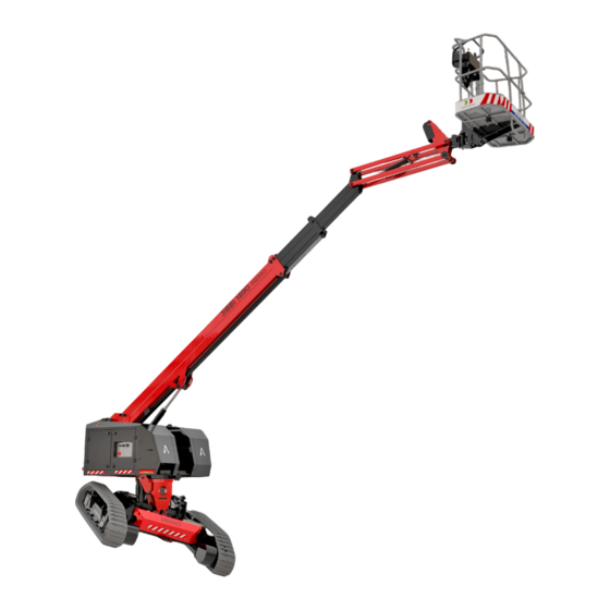
JIBBI 1890 PRIMO
Crawler Telescopic Boom
JIBBI
1250 EVO
Carrum Downs (HQ)
Hunter Valley, NSW
(03) 8795 2999
(02) 9589 6200
vic@alfasi.com.au
hv@alfasi.com.au
Derrimut, VIC
Sydney, NSW
(03) 8795 2999
(02) 9589 6200
vic@alfasi.com.au
nsw@alfasi.com.au
1300 551 108 | info@alfasihire.com.au | alfasihire.com.au
1300 551 108 | efleet@alfasihire.com.au
Brisbane, QLD
(07) 3370 2800
qld@alfasi.com.au
Gold Coast, QLD
(07) 3370 2800
gc@alfasi.com.au
Mackay, QLD
(07) 3370 2800
nq@alfasi.com.au
Karratha, WA
(08) 6187 3000
wa@alfasi.com.au
Advertisement
Table of Contents

Related Manuals for ALMACRAWLER JIBBI PRIMO Series


Summary of Contents for ALMACRAWLER JIBBI PRIMO Series
- Page 1 JIBBI 1890 PRIMO Crawler Telescopic Boom JIBBI 1250 EVO 1300 551 108 | efleet@alfasihire.com.au Carrum Downs (HQ) Hunter Valley, NSW Brisbane, QLD Mackay, QLD (03) 8795 2999 (02) 9589 6200 (07) 3370 2800 (07) 3370 2800 vic@alfasi.com.au hv@alfasi.com.au qld@alfasi.com.au nq@alfasi.com.au Derrimut, VIC Sydney, NSW...
- Page 2 JIBBI 1890 PRiMO PRiMO. The first full electric, self- levelling, tracked telescopic boom with PRiMO electric drive and fully removable power pack. Designed to eliminate jobsite SELF-PROPELLED obstacles, with an 18m working height, SELF-LEVELLING it can safely be driven up to 14m and 15°...
- Page 3 BATTERY TYPE WEIGHT RECHARGE FULL ELECTRIC TIPO BATTERIA PESO RICARICA Lead acid 720 Kg 6,5 h WITH COMPLETELY 420Ah 48V REMOVABLE BATTERY TYPE WEIGHT RECHARGE FULL ELECTRIC TIPO BATTERIA PESO RICARICA Lithium 300 Kg 5,0 h POWER PACK 330Ah 48V Lead acid WITH COMPLETELY 720 Kg...
- Page 4 JIBBI 1890 PRiMO Technical data Dati tecnici Max working height 17,90 m Altezza massima di lavoro Max height basket floor 15,90 m Altezza piano calpestio Max moving height 13,80 m Altezza di traslazione Max outreach (load 140 kg) 9,92 m Sbraccio massimo (carico 140 Kg) Max outreach (250 kg) 8,32 m...
- Page 5 JIBBI 1890 PRiMO JIBBI 1890 PRiMO REMOVABLE POWER PACK REMOVABLE POWER PACK 1300 551 108 | info@alfasihire.com.au | alfasihire.com.au...
- Page 6 1300 551 108 | info@alfasihire.com.au | alfasihire.com.au...
- Page 7 JIBBI PRIMO SERIES: JIBBI 1890 PRIMO USE AND MAINTENANCE ENGLISH Original Instructions ALMAC S.r.l. e-mail: info@almac-italia.com 39 0375 83 35 27 Phone + Fax. +39 0375 78 43 50 Registered office Operational Headquarters Viale Ruggeri 6 / A Via Caduti sul Lavoro 1...
- Page 8 PAGE 2 DATE REVISION DESCRIPTION 2023/01/09 • First issue of the document. 2023/02/01 • Various updates.
-
Page 9: Table Of Contents
PAGE 3 SUMMARY GENERAL INFORMATION..................7 ................7 EGULATORY AND LEGAL ASPECTS 1.1.1 Documentation supplied................7 1.1.2 Notification of commissioning, first check, subsequent periodic checks and transfer of ownership......................7 1.1.2.1 Notification of commissioning and first check (only for Italy)............8 1.1.2.2 Periodic checks following the first check. - Page 10 PAGE 4 5.1.3 Push-button panel on the platform..............39 5.1.3.1 "Dead man" system...................... 40 5.1.3.1.1 Enabling commands by means of the ON button..............40 5.1.3.1.2 Enabling commands by foot pedal (OPTIONAL) ..............40 5.1.3.2 Traction and steering controls..................41 5.1.3.2.1 Traction speed selector switch.
- Page 11 PAGE 5 ................. 71 OADING WITH LOADING RAMP ..................71 OADING WITH A FORKLIFT ..................72 OADING WITH A CRANE ............72 IXING THE MACHINE ON THE MEANS OF TRANSPORT EMERGENCY COMMANDS..................74 7.1.1 Emergency recovery of the incapacitated operator..........74 7.1.2 Emergency recovery of the incapacitated operator in the presence of an overload alarm.
- Page 12 PAGE 6 11.3 .................. 115 RANSFERS OF WNERSHIP 12 FUNCTIONAL DIAGRAMS..................116 12.1 WIRING DIAGRAMS..................116 12.2 HYDRAULIC DIAGRAMS................... 116...
-
Page 13: General Information
PAGE 7 1 GENERAL INFORMATION. This document contains proprietary information. All rights reserved. This document cannot be reproduced, in whole or in part, without the prior written consent of ALMAC s.r.l. The use of this document is permitted only to the customer to whom the manual was provided as a kit with the equipment, and only for purposes of use and maintenance of the equipment to which the manual refers. -
Page 14: Notification Of Commissioning And First Check (Only For Italy)
PAGE 8 1.1.2.1 Notification of commissioning and first check (only for Italy). In Italy, the owner of the Elevating Work Platform (PLE) must report its commissioning to INAIL and submit it to mandatory periodic checks. The first check is carried out by INAIL within sixty days from the request, after which the employer can make use of the ASLs or authorized public or private entities. -
Page 15: Training, Information And Training Of Operators
PAGE 9 1.1.3 Training, information and training of operators. Training, information and training of operators are legal obligations for the employer. The employer must in fact ensure that the workers in charge of the use of the equipment receive adequate and specific training to allow their use in a suitable and safe way, also in relation to the damage that may be caused to other people and things. -
Page 16: Request For Intervention Under Warranty And Technical Assistance
PAGE 10 1.1.5.2 Request for intervention under warranty and technical assistance. Any requests for spare parts or technical interventions under warranty must be reported to ALMAC S.r.l. as soon as a defect is found. For any request for assistance, always contact the ALMAC technical assistance service as indicated below: OPERATIONAL REGISTERED OFFICE HEADQUARTERS... -
Page 17: Description And Intended Use Of The Machine
PAGE 11 1.2 Description and intended use of the machine. The machine described in this manual is a self-propelled Elevating Work Platform or, as described by the EN280 technical standard, a mobile machine designed to move people to work positions, in which they perform tasks while remaining on the work platform, with the understanding that persons enter and exit the work platform only through access positions at ground or chassis level, and which consists of at least a work platform with controls, an extendable structure (lift arms) and a frame. - Page 18 PAGE 12 Ground inclination; Opening angle of the main arm; Position of the telescopic extension of the arm; Opening angle of the jib; Loading on the platform. By means of the display at the ground control station and the LED indicators on the control panel in the platform, the operator on board is constantly informed of the operating limits reached and the movements allowed.
-
Page 19: Operating Positions
PAGE 13 1.3 Operating positions. The normal operating position is on the platform, whereas there is a control station on the ground for platform emergency recovery, emergency stop, maintenance, and machine on/off. 1.3.1 Foot-driven use (function reserved for ALMAC authorized technicians). It is possible, by means of an additional control console (provided to ALMAC authorised technicians only) to drive the machine by walking operator, during loading/unloading operations of the machine from containers or closed means of transport where it is necessary to remove the platform beforehand. -
Page 20: Identification
PAGE 14 1.6 Identification. In the event of a request for spare parts and for interventions, the data shown on the registration plate located on the turret or on the identification plate on the platform must always be mentioned. In case of loss or illegibility of the plates (as well as for the various adhesive plates located throughout the machine), it must be restored as quickly as possible. -
Page 21: Definitions And Locations Of The Main Components
PAGE 15 1.7 Definitions and locations of the main components The main components of the machine are shown in the following images. This manual deals with different models and equipment so some images may differ slightly from the model owned. 1. - Page 22 PAGE 16 38. Headlights for driving path lighting (optional) 39. Pothole sensors (optional) 40. Working lights platform (optional) 41. Anti-collision sensors on platform (optional) 42. Anti-crushing sensor on platform (optional) 43. Connector for additional console connection (optional for SERVICE) for loading/unloading Figure 3...
-
Page 23: Technical Data, Dimensions And Working Diagrams
PAGE 17 2 TECHNICAL DATA, DIMENSIONS AND WORKING DIAGRAMS. 2.1 JIBBI 1890 PRIMO. 2.1.1 General technical data JIBBI 1890 PRIMO. Dimensions: Metric Imperial Maximum working height (1) 17.9 58’ 9” Maximum height of the platform surface (1) 15.9 52’ 2” Maximum working outreach from centre of slew ring –... -
Page 24: Technical Data Jibbi 1890 Primo Version - Lth 330 Battery
PAGE 18 2.1.2 Technical data JIBBI 1890 PRIMO version - LTH 330 battery. Technical data Metric Imperial Lithium battery - LiFePO4 Machine weight (1) 5890 13000 Battery nominal voltage Battery nominal capacity Battery pack weight 1120 x 605 44” x 24” Battery pack size h=535 h=21”... -
Page 25: Technical Data Jibbi 1890 Primo Version - Lth 440 Battery
PAGE 19 2.1.3 Technical data JIBBI 1890 PRIMO version - LTH 440 battery. Technical data Metric Imperial Lithium battery - LiFePO4 Machine weight (1) 5910 13000 Battery nominal voltage Battery nominal capacity Battery pack weight 1120 x 605 44” x 24” Battery pack size h=535 h=21”... -
Page 26: Technical Data Jibbi 1890 Primo Version - Elc 420 Battery
PAGE 20 2.1.4 Technical data JIBBI 1890 PRIMO version - ELC 420 battery. Technical data Metric Imperial Lithium battery - LiFePO4 Machine weight (1) 6310 13900 Battery nominal voltage Battery nominal capacity (C5) Battery pack weight 1580 1200 x 605 47”... -
Page 27: Jibbi 1890 Primo Working Diagrams (All Versions)
PAGE 21 2.1.5 JIBBI 1890 PRIMO working diagrams (all versions). 2.1.5.1 Working diagrams. Maximum height and maximum outreach. Drive inhibited. -
Page 28: Working Diagrams. Translation Allowed
PAGE 22 2.1.5.2 Working diagrams. Drive permitted. 2.1.5.3 Access position and transport dimensions. -
Page 29: Max Height Of Walking Surface For Safety Speed Insertion (Lowered Travel Position)
PAGE 23 2.1.5.4 Max height of platform surface with full drive speed permitted (LOWERED TRAVEL POSITION). The following pictures show the limit positions of the main boom and jib beyond which the decreased safety travel speed for elevated platform is automatically activated. -
Page 30: Safety Information, Obligations And Prohibitions
PAGE 24 3 SAFETY INFORMATION, OBLIGATIONS AND PROHIBITIONS. 3.1 Personal Protective Equipment (PPE). For completely safe use of the machine it is mandatory to wear the appropriate Personal Protective Equipment indicated below, in addition to any additional devices related to the risks connected to the activity carried out to be identified by the Employer (example: in cases of activities in a noisy environment, the use of hearing protectors, etc. -
Page 31: Safety Rules
PAGE 25 3.2 Safety rules. 3.2.1 General safety rules. • Read this manual carefully before proceeding with start-up, use, maintenance or other interventions on the machine; • The use of the machine is reserved for adults (18 years of age) and adequately instructed and trained; •... - Page 32 PAGE 26 • It is forbidden to transport large materials or panels, as they increase wind resistance, causing a strong risk of overturning.
-
Page 33: Handling And Displacements
PAGE 27 3.2.2 Handling and displacements • It is forbidden to drive on roads open to traffic. The machine is not approved for this purpose. • Do not operate on soft ground to avoid the risk of instability and machine downtime. To avoid overturning, it is necessary to comply with the maximum permissible slopes indicated in the chapter relating to the technical characteristics of each model under the heading “Stability limits”;... -
Page 34: Stages Of Work
PAGE 28 Figure5 3.2.3 Stages of work. • The machine is equipped with numerous sensors on its moving parts (arms, turret rotation, telescopic extension, etc.) which constantly monitor the configuration of the machine and the loads carried on the platform. Any alarms or operation inhibitions are clearly indicated by the LED lights on the control station on the platform;... - Page 35 PAGE 29 Figure 6...
-
Page 36: Wind Action And Beaufort Scale
PAGE 30 3.2.4 Wind action and Beaufort scale. The wind is one of the possible causes of overturning. Use of the machine with winds exceeding 12.5 m / s (45 km / h - 28 mph) is prohibited. There is no anemometer on the standard machine; to monitor the wind speed, refer to the table below, where the operating wind limit is defined as N.6 according to the BEAUFORT INTERNATIONAL SCALE. -
Page 37: Ground Suitability And Pressure To The Ground Of The Machine
PAGE 31 3.2.5 Ground suitability and ground pressure of the machine. 3.2.5.1 Bearing capacity of the ground. Always, before using the machine, the operator must check that the floor or ground is suitable to withstand the load and pressures generated by the machine, and such as not to slide the machine due to high slope and / or poor grip. - Page 38 PAGE 32 JIBBI 1890 PRIMO LTH330 JIBBI 1890 PRIMO LTH440 JIBBI 1890 PRIMO ELC420 Formula Metric Imperial Metric Imperial Metric Imperial 5890 kg 13000 lbs 5910 kg 13000 lbs 6310 kg 13900 lbs 3100 kg 6800 lbs 3100 kg 6800 lbs 3160 kg 6800 lbs 250 kg...
-
Page 39: Ground Inclination
PAGE 33 LOAD BEARING VALUE TYPES OF SOIL Kg / cm² lb / in² Non-compact filler earth 0 – 1 0 - 14 Mud, peat, etc. Sand Gravel Crumbly earth Soft earth Stiff earth Semi-solid earth Solid earth Rock 15 – 30 210 - 420 It is forbidden to use the machine if the maximum pressure generated on the ground is higher than the permitted bearing capacity value indicated in the table. -
Page 40: Live Power Lines
PAGE 34 3.2.6 Live power lines The machine is not electrically isolated and does not provide protection from contact or proximity to electrical lines. It is mandatory to maintain a minimum distance from the electrical lines in accordance with the local regulations in force and according to the following table. -
Page 41: Installation And Preliminary Checks
PAGE 35 4 INSTALLATION AND PRELIMINARY CHECKS. The machine is generally delivered completely assembled, therefore it can perform all the functions provided by the manufacturer in complete safety. There is no need to perform any preliminary operations. To unload the machine, follow the instructions in the "handling and transport" chapter. Place the machine on a sufficiently consistent surface with a slope lower than the maximum allowed (see technical characteristics "Stability limits") before operating it. -
Page 42: Defects Found During Pre-Use Checks
PAGE 36 4.3 Defects found during pre-use checks. If during the pre-use checks (or during the use of the machine), the operator finds a defect that can generate dangerous situations or suspects that there may be malfunctions, the machine must be placed in a safe condition (isolate the same, apply a defect sign) and report the anomaly to the employer and contact an authorised service centre. -
Page 43: Method Of Use
PAGE 37 5 METHOD OF USE. 5.1 Platform control station. 5.1.1 Document compartment on the platform. There is a document compartment in the platform as shown in the image on the side. At least one copy of the following documents must always be kept in this compartment: Instruction manual... - Page 44 PAGE 38 To operate with the push-button panel on the platform, remove the protective cap "A", slide it behind the push-button panel, and fix it in position using the automatic clips "B" Figure 11...
-
Page 45: Push-Button Panel On The Platform
PAGE 39 5.1.3 Push-button panel on the platform. Figure 12 1. DRIVE CONTROL JOYSTICK 2. RIGHT STEERING BUTTON 3. LEFT STEERING BUTTON 4. MAIN BOOM AND TURRET ROTATION CONTROL JOYSTICK 5. TELESCOPIC BOOM PROPORTIONAL CONTROL LEVER 6. JIB PROPORTIONAL CONTROL LEVER 7. -
Page 46: Dead Man" System
PAGE 40 5.1.3.1 "Operator presence" system. With the machine on, if the platform control station has been selected, after activating the EMERGENCY STOP button (16) by turning it clockwise, the green LED (11) will flash. Flashing green LED (11) indicates that the controls are not enabled. -
Page 47: Traction And Steering Controls
PAGE 41 5.1.3.2 Drive and steering controls. Attention: Before carrying out any operation to move the machine, check that there are no people or obstacles in the vicinity or in the range of action of the machine. In any case, proceed with the utmost caution. -
Page 48: Traction Speed Selector Switch
PAGE 42 In low platform conditions (ACCESS POSITION and LOWERED TRAVEL POSITION) the drive and steering command can take place at the same time as the turret rotation command in order to facilitate machine movement in tight spaces. 5.1.3.2.1 Drive speed selector switch. The green lights alongside indicate the following traction speeds: A. -
Page 49: Steering While Moving
PAGE 43 5.1.3.2.2 Steering while moving. If one of the steering buttons (2,3) is pressed when the drive joystick (1) has already been activated, the machine performs "soft" steering by reducing the forward speed of one of the two tracks. Releasing the steering button, the machine returns to forward in straight line. -
Page 50: Manual Control Of Turret Levelling
PAGE 44 PROACTIVE LEVELLING is always active when the platform is elevated and the machine is in the working diagrams where drive is allowed. It does not depend on the button (20). This automatic function allows the turret and the extendable structure to be kept level while you are controlling drive and steering on sloping terrain whose slope changes gradually. -
Page 51: Platform Handling (Ascents, Descents, Rotations)
PAGE 45 5.1.3.4 Platform handling (ascents, descents, rotations). The joystick (4), proportional levers (5,6,7) and pushbuttons (8, 9,12) are used to move the platform (ascending, descending, rotating). If you are in a condition where platform movement commands are available, once you have enabled the controls through the "operator presence"... -
Page 52: Ascent / Descent Of The Main Boom
PAGE 46 Attention: RISK OF OVERTURNING The system is not able to level the rotating plane of the fifth wheel if the ground is inclined more than 15°. If the leveling system fails, the machine enters the tilt alarm, and the commands to return the platform to the ground are available. -
Page 53: Jib Up/Down
PAGE 47 5.1.3.4.6 Jib up/down. To perform the jib up/down operation, the proportional lever (5) is used by operating it forward to obtain the ascent of the jib, or backwards to obtain the descent. The control is proportional so it is possible to modulate the operating speed by moving the lever more or less deeply. -
Page 54: Other Functions And Devices Of The Control Panel
PAGE 48 5.1.3.5 Other functions and devices of the control panel. 5.1.3.5.1 Emergency stop. Pressing the red emergency stop button (16) will stop the ongoing movements, but the control system will stay turned on. In order to restart normal functions from the platform control station after any operation of the emergency stop button, it is necessary: Rotate the button clockwise by a quarter of a turn (or pulling outwards, depending on the type of button);... -
Page 55: Warning Lights
PAGE 49 5.1.3.5.6 Warning lights. A. OVERLOAD INDICATOR LIGHT; B. LIMIT REACH / ANTI-COLLISION INDICATOR LIGHT; C. BATTERY LEVEL GREEN INDICATOR LIGHT; D. TURRET TILT WARNING LIGHT; E. PLATFORM TILT WARNING LIGHT; F. LEVELLED TURRET GREEN LIGHT. Figure 19 OVERLOAD INDICATOR (depends on workload selection): Turned on with steady red light: The overload indicator is active. - Page 56 PAGE 50 BATTERY LEVEL GREEN INDICATOR LIGHT: Turned on with steady green light: battery charge status is between 61%-100%. Turned on with slow flashing green light: battery charge status is between 21%-60%. Turned on with fast flashing red light: Low battery. The battery charge status is less than 20%.
- Page 57 PAGE 51 LEVELLED TURRET GREEN LIGHT: Turned on with steady green light: The turret is correctly levelled. Green light off: The turret is not correctly levelled. A turret tilt alarm is active as signalled by the red light “D”...
-
Page 58: Ultrasonic Anti-Crushing And Anti-Collision Kits (Optional)
PAGE 52 5.1.4 Ultrasonic anti-crushing and anti-collision kits (OPTIONAL). 5.1.4.1 Operator anti-crushing kit (OPTIONAL). As an option, it is possible to install an ultrasonic sensor in the upper part of the platform, as shown in the figure. This factory-adjusted accessory detects obstacles at a vertical distance of less than 1.5 m from the handrail and alerts the... -
Page 59: Platform Anti-Collision Kit (Optional)
PAGE 53 5.1.4.2 Platform anti-collision kit (OPTIONAL). As an option, it is possible to install a pair of ultrasonic sensors in the lower part of the platform, as shown in the figure. This accessory, adjusted in the factory, detects obstacles at a distance of fewer than 0.7 m from the platform and warns the operator of the danger of collision by means of an appropriate warning on the... -
Page 60: Pothole And Anti-Collision Turret Kit (Optional)
PAGE 54 Warning: it is not a safety device, but an aid to the operator with the purpose of reducing the risk of entrapment of the operator at the machine controls. It remains the responsibility of the operator to monitor the surrounding environment by working with the machine. 5.1.6 Pothole and anti-collision turret kit (OPTIONAL). -
Page 61: Pothole Kit (Optional)
PAGE 55 5.1.6.1 Pothole kit (OPTIONAL). During drive, if one or more "A" sensors detect a depression/pot-hole dangerous for machine stability: Basic function: On the display panel "C" the red warning light "D" relating to the danger zone turns on with a steady light;... - Page 62 PAGE 56 Attention: What is described is not a safety device, but an aid to the operator with the aim of reducing the risk of collision. It remains the responsibility of the operator to monitor the surrounding environment by working with the machine.
-
Page 63: Ontrol Station On The Ground
PAGE 57 5.2 Control station on the ground. The ground control station is located in the turret. It contains the electronic control units that manages all the functions of the machine and has the function of: Turn the machine on and off; Select the enabled control station (on the ground or on the platform);... -
Page 64: Main Key Switch / Control Station Selector
PAGE 58 9. TELESCOPIC EXTENSION/RETRACTION BUTTONS 10. BOOM UP/DOWN/TURRET LEVELLING BUTTONS 11. JIB UP/DOWN BUTTONS 12. PLATFORM ROTATION BUTTONS 13. PLATFORM LEVELLING CORRECTION BUTTONS 14. CIRCULAR DISPLAY 15. BATTERY CHARGER INDICATOR LIGHT 16. MOVEMENT/ALARM BUZZER 17. GROUND CONTROL LIGHT (OPTIONAL) 18. -
Page 65: Emergency Override Button With Leaded Protection
PAGE 59 5.2.4 Emergency Override Button with leaded protection. This button (5, lead-protected) is used for emergency recovery of an operator who is incapacitated, using the ground control station commands by temporarily disabling certain safety controls (e.g., operator incapacitated and machine locked due to overload) regardless of the position of the key switch (ground or platform controls). -
Page 66: Turret Rotation/Leveling Buttons
PAGE 60 5.2.7 TURRET ROTATION/LEVELING buttons. To control the rotation of the turret from the ground control station, press the "ON" enable button (2) and one of the buttons (8) in the image on the right: 8-A: for clockwise rotation; 8-B: for counterclockwise rotation. -
Page 67: Jib Up/Down Buttons
PAGE 61 5.2.10 JIB UP/DOWN buttons. To control the raising/lowering of the jib from the ground control station, press the enabling button "ON" (2) and one of the buttons (11) in the image on the right: 11-A: for raising; 11-B: for lowering. Figure 28 5.2.11 PLATFORM ROTATION buttons. -
Page 68: Circular Display
PAGE 62 5.2.13 Circular display. The circular display (14) represents the man- machine interface and contains the following indications: a. Bars indicating remaining battery charge status; b. Error messages from the command devices. c. Working hours. Using the "D" button it is possible to change the message page;... - Page 69 PAGE 63 Boom telescopic extension sensor does not move during command Boom telescopic retraction sensor does not move during command Boom telescopic extension sensor moves without being commanded Boom telescopic retraction sensor moves without being commanded Main boom rising sensor does not move during command Main boom lowering sensor does not move during command Main boom up/down sensor moves without being commanded Main boom up/down sensor moves in the opposite direction to the command...
- Page 70 PAGE 64 Excessive deviation of carriage tilt sensor signals N.A. N.A. Excessive deviation of carriage tilt sensor signals Incorrect reset of the turret tilt sensor. New reset required N.A. N.A. Excessive deviation of turret tilt sensor signals N.A. N.A. Excessive deviation of turret tilt sensor signals Incorrect reset of the platform tilt sensor.
- Page 71 PAGE 65 EV14A - Telescopic extension error EV14B - Telescopic retraction error EV17A - Jib ascent error EV17B - Jib descent error EV18A - CW turret rotation error EV18B - CCW turret rotation error EV19A - Boom ascent error EV19B - Boom descent error EV3A - Left turret levelling error EV3B - Right turret levelling error EV4A - Forward turret levelling error...
-
Page 72: Battery Charger Indicator Light
PAGE 66 5.2.14 BATTERY CHARGER indicator light. The BATTERY CHARGER indicator light (15) is active when the battery charger is powered. The indicator light indicates the progress of charging as follows: Fast flashing GREEN light: battery charging started; Slow flashing GREEN light: final stage of battery charging; Steady GREEN light: battery charging is completed. -
Page 73: Ccess To The Platform
PAGE 67 5.3 Access to the platform. The access position is the only position allowed for people and materials loading and unloading from the platform. Procedure to access the platform: Lift the inlet rod (1); Get on the platform using the uprights (2); Drop or lower the inlet rod (1);... -
Page 74: Tarting The Machine
PAGE 68 5.4 Starting the machine. To start the machine, the operator must: Release ground control station emergency stop button (2) by turning it clockwise by a quarter of a turn; Turn the key selector (1) of the ground control station, bringing it to the position represented by the blue box (platform controls);... -
Page 75: Normal Shutdown
PAGE 69 5.5 Stopping the machine. 5.5.1 Normal shutdown. During normal use of the machine, releasing the joysticks and switches stops the relative command. 5.5.2 Emergency stop. In case of need, the operator can command the emergency stop of the machine both from the platform control panel and from the ground control station by pressing one of the red emergency buttons present (see image on the side). -
Page 76: Uick Replacement Of The Battery Pack
PAGE 70 5.7 Quick replacement of the Battery Pack. The battery pack (A) can be easily replaced to increase the machine's working autonomy. To remove the battery pack (A): Level turret then turn the machine off; 2. Open the side doors (B); 3. -
Page 77: Loading And Transport
PAGE 71 6 LOADING AND TRANSPORT. Before transporting the machine between different workplaces with a means of transport, it is necessary to find out about the overall dimensions and the transportable mass limits, on the basis of the road traffic regulations in force. -
Page 78: Loading With A Crane
PAGE 72 6.3 Loading with a crane. It is possible to load the machine on the platform of the means of transport using a crane. By means of four lifting bands of appropriate length and capacity (see the weight of the machine in the TECHNICAL DATA chapter), hooking to the lifting points indicated by the adhesive plates placed on the machine and shown alongside. - Page 79 PAGE 73 Warning: Do not over-tension the fastening straps to avoid damaging the machine structure. Attention: Before transporting, make sure that the boom is COMPLETELY DOWN.
-
Page 80: Emergency Commands
PAGE 74 7 EMERGENCY COMMANDS. While using the emergency controls, a qualified operator, who must always be present on the ground, assumes responsibility for moving the machine and the operator on board using the emergency modes described below. The operator using the emergency controls must always check that the machine movements take place in accordance with the commands activated. -
Page 81: Emergency Recovery Of The Incapacitated Operator In The Presence Of An Overload Alarm
PAGE 75 7.1.2 Emergency recovery of an incapacitated operator in the presence of an overload alarm. In the event that the operator on the platform is unable to return to the ground by using the platform controls and with the simultaneous presence of an overload alarm, the machine is blocked. A qualified operator can operate the emergency controls on the ground control station. -
Page 82: Emergency Recovery With A Manual Pump
PAGE 76 7.1.3 Emergency recovery with a manual pump. 7.1.3.1 Operator emergency recovery. In the event of a power failure, to recover a blocked operator, a qualified operator on the ground must use the manual controls activated by the manual pump in the manner described below. The manual emergency controls are located on the rotating turret: 1. - Page 83 PAGE 77 To understand the correspondence between the manual control and the corresponding movement, pay attention to the screen printing placed on the machine and represented in the following image. Press the manual controls of the valves to activate movements indicated with “A”,...
-
Page 84: Maintenance
PAGE 78 8 MAINTENANCE. 8.1 Safety rules during maintenance. Always carry out maintenance operations in conditions of maximum safety, with the machine stopped and off, having extracted the key from the control panel on the ground, with the emergency buttons pressed and wearing the individual protection devices suitable for the operations to be performed. -
Page 85: Ordinary Maintenance
PAGE 79 8.2 Ordinary maintenance. Checks and maintenance must be carried out as indicated in the table below. PERIODIC TABLE OF ORDINARY MAINTENANCE Machine cleaning Cleaning of plates and warning lights Visual check of operational / warning DECALS are legible Functional and serviceability checks of operator controls Functional checks of machine operation Confirmation of no fault codes present... -
Page 86: Cleaning The Machine And Adhesive Plates
PAGE 80 8.2.1 Cleaning the machine. To clean the machine properly, you can use non-pressurized water jets, adequately protecting the following details: Electrical components; Ground control panel and console on platform; Electric motors and battery. After cleaning the machine, dry all the details, check the integrity / legibility of the instructional and warning DECALS and grease the areas with grease nipples or the sliding pads of the telescopic appendages of the arms and stabilizers. - Page 87 PAGE 81 Operate the emergency button on the platform control station and verify that the platform control console is turned off. Release the emergency button at the end of this test. Activate the emergency button of the ground control station, and check that the machine is completely off and that no function is allowed.
-
Page 88: Visual Inspection Of The Structural Elements Of The Machine
PAGE 82 8.2.3 Visual inspection of the structural elements of the machine. According to the periodicity described in the maintenance table, and always before each use of the machine, it is necessary to visually check the integrity of the main structural elements of the machine, with particular attention to the welds. -
Page 89: Visual Check Screw Tightness / Screw Tightening
PAGE 83 8.2.4 Visual check screw tightness / Screw tightening. According to the periodicity described in the maintenance table, and always before each use of the machine, it is necessary to visually check the tightening of the elements indicated alongside, i.e.: 1. -
Page 90: Greasing Joints, Telescopic Extensions And Slewing Ring
PAGE 84 8.2.5 Greasing joints, telescopic extensions and slewing ring. According to the periodicity described in the maintenance table, proceed with greasing the points equipped with grease nipples and the telescopic appendages indicated in the image alongside. To grease the telescopic arms, fully extend the extensions (with the jib completely closed, and no load on the platform) by raising the boom slightly to avoid interference between the basket and the... -
Page 91: Hydraulic Oil Level Check / Oil Change
PAGE 85 8.2.6 Hydraulic oil level check / oil change. According to the periodicity described in the maintenance table, and always before each use of the machine, it is necessary to check the level of hydraulic oil in the tank, through the visual indicator indicated alongside (A). -
Page 92: Hydraulic Oil Filter Replacement
PAGE 86 8.2.7 Hydraulic oil filter replacement. According to the periodicity described in the maintenance table, it is necessary to replace the hydraulic oil filters at the same time as changing the hydraulic oil. To replace the filters USE ORIGINAL SPARE PARTS ONLY. Contact ALMAC for assistance with the procurement of the material. -
Page 93: Suction And Return Filters
PAGE 87 8.2.7.2 Suction and return filters. To replace the suction filters (A) located inside the hydraulic tank and the filter cartridge (B) of the return filter (C) in the same operation: Turn off the machine completely; Empty the tank (see previous chapters); Unscrew all screws (D) of the tank cover (E) and remove the tank cover;... -
Page 94: Traction Reduction Gear Oil Level Check / Oil Change
PAGE 88 8.2.8 Drive reduction gear oil level check / oil change. According to the periodicity described in the maintenance table, it is necessary to check the oil level in the traction reducers according to the following procedure. To check the level: Command the travel until the plugs (A) and (B) are in the position shown alongside;... -
Page 95: Tracks: Check For Wear, Tensioning And Replacement
PAGE 89 8.2.9 Tracks: check for wear, tensioning and replacement. According to the periodicity described in the maintenance table, and always before each use of the machine, it is necessary to check the state of wear and the correct tensioning of the tracks. 8.2.9.1 Track wear check. - Page 96 PAGE 90 Pull the track out of its seat by levering between the track and the idler wheel with a pry bar while an operator from the platform control station operates the traction control while holding down the mode button so as not to activate the automatic tensioning control; Install the new track following the reverse procedure, matching the toothed wheel to its seats, then inserting it on the idler wheel;...
-
Page 97: Extension Chains: Wear Control, Tensioning And Lubrication
PAGE 91 8.2.10 Extension chains: Wear control, Tensioning and Lubrication. According to the periodicity described in the maintenance table, check the extension chains: Wear control; Tension control; Lubrication. 8.2.10.1 Chain wear check. The wear control of the telescopic extension / retraction chains consists mainly of measuring a 10-step stretch and evaluating the percentage elongation. -
Page 98: Check Wear And Register Of Sliding Pads
PAGE 92 8.2.10.3 Chain lubrication. The extension / return chains must always be kept lubricated. Lubricate the extension / return chains according to the frequency described in the maintenance table. For correct lubrication it is necessary: Remove the telescopic boom in safety conditions (machine on flat ground, in stable conditions, without load on the platform and with the jib completely retracted);... -
Page 99: Turret Rotation Game Control
PAGE 93 8.2.12 Turret rotation clearance check. According to the periodicity described in the maintenance table, check the play of the turret rotation system. The turret rotation system used on ALMAC machines makes it possible to have no play at the base of the rotating turret by applying horizontal forces to the platform. -
Page 100: Overload Control Device Check
PAGE 94 8.2.14 Overload control device check. According to the periodicity described in the maintenance table, check the operation of the platform overload control system. The work platform support incorporates a sensor that detects the load present on the platform. If the rated load is exceeded by 20% of the rated load, and the platform is not in the access position, the overload alarm is activated and the... -
Page 101: Machine Sensor Control
PAGE 95 8.2.15 Machine sensor check. All moving parts of the machine, except for the rotation of the platform, are monitored by sensors. Based on the information received from these sensors, the control system adapts the operation of the machine in relation to: Work diagrams;... -
Page 102: Battery
PAGE 96 8.2.19 Battery. The battery is a component of fundamental importance in the operation of the machine. Maintaining it over time is important to increase its life, but also to limit problems and reduce the operating costs of the machine itself. In general, keep in mind the following warnings: Charge the lead-acid battery in a ventilated area;... -
Page 103: Lithium Battery (Lth Versions)
PAGE 97 8.2.19.2 LITHIUM battery (LTH versions). The LITHIUM battery present on the LTH version machines feeds the power circuits of the machine and, through a DC-DC converter, also the control circuit battery. The battery consists of lithium-ion cells and an advanced electronic management system, integrated ... -
Page 104: Lithium Battery Charging (Lth Versions)
PAGE 98 8.2.19.2.2 LITHIUM battery charging (LTH versions) To charge the LITHIUM battery, it is necessary to connect the charger to the mains or to a vehicle charging station. The battery can be recharged both when the battery pack is correctly installed on the machine and when it is on the ground;... - Page 105 PAGE 99 8.2.19.2.2.2 Recharging by means of a vehicle charging station. The charging station must be of alternating current AC type 2, IEC 62196-2, 32A / 250V (AC). It is also necessary to keep in mind the following: Use a specific cable; Do not use cables or extensions longer than 5 meters;...
-
Page 106: Traction Battery (Elc Versions)
PAGE 100 8.2.19.3 TRACTION battery (ELC versions). The TRACTION battery present on the ELC version machines supplies the power circuits of the machine and, through a DC-DC converter, also the control circuits. The battery is made up of lead-acid elements combined in order to provide the correct voltage and ... - Page 107 PAGE 101 TOPPING UP THE BATTERY WATER USING A CENTRALIZED FILLING KIT. a. Open the doors on the battery side (3) and locate the quick coupler (4) of the central filling system; b. Connect the quick coupling to the external counterpart connected to a tank containing DISTILLED WATER and open the tap.
-
Page 108: Traction Battery Charging (Elc Versions)
PAGE 102 8.2.19.3.2 TRACTION battery charging (ELC versions). To recharge the TRACTION battery, the battery charger must be connected to an electrical network equipped with all the protections in accordance with current safety standards, and which following characteristics (depending on the country in which the machine is put into service): Power supply voltage 115-230V AC ±... -
Page 109: Demolition
PAGE 103 9 DEMOLITION. 9.1 Machine life. The machine has been designed for a duration of 10 years in normal working environments, considering correct use and adequate maintenance. 9.2 Decommissioning and demolition. Once the end of its technical and operational life has been reached, the machine must be subjected to a detailed and complete check / overhaul by the manufacturer or by specialized and qualified technicians. -
Page 110: Ce Declaration Of Conformity (Fac-Simile)
PAGE 104 10 CE DECLARATION OF CONFORMITY (FAC-SIMILE). -
Page 111: Control Register
PAGE 105 11 CONTROL REGISTER. This CONTROL REGISTER is issued to the user of the machine in accordance with Annex 1 of the Machinery Directive 2006/42 / EC; It must always accompany the machine even following changes in ownership and is used to record events concerning the life of the machine in the appropriate spaces, and more precisely: •... -
Page 112: Register Of Periodic Inspections And Checks By The Control Bodies
PAGE 106 11.1 Register of PERIODIC INSPECTIONS AND CHECKS by the control bodies. Body; Name and surname; Date Remarks Signature and stamp Verification Verification Verification Verification Verification Verification Verification Verification Verification 10th Verification If the machine is kept in service for a period exceeding 10 years, after having subjected it to an extraordinary check, record the subsequent periodic checks below. -
Page 113: Register Of Periodic Inspections By The Owner
PAGE 107 11.2 Register of PERIODIC INSPECTIONS by the owner. For the checks in this section, refer to the MAINTENANCE chapter. FUNCTIONAL CHECKS Name surname; Date Remarks Signature and stamp 1st year 2nd year 3rd year 4th year 5th year 6th year 7th year 8th year... - Page 114 PAGE 108 VISUAL INSPECTION OF THE STRUCTURAL ELEMENTS OF THE MACHINE Name surname; Date Remarks Signature and stamp 1st year 2nd year 3rd year 4th year 5th year 6th year 7th year 8th year 9th year 10th year GREASING JOINTS, TELESCOPIC EXTENSIONS AND SLEWING RING Name surname;...
- Page 115 PAGE 109 HYDRAULIC OIL REPLACEMENT Name surname; Date Remarks Signature and stamp 1st year 2nd year 3rd year 4th year 5th year 6th year 7th year 8th year 9th year 10th year HYDRAULIC OIL FILTER REPLACEMENT Name surname; Date Remarks Signature and stamp 1st year 2nd year...
- Page 116 PAGE 110 TRACK REDUCTION GEAR OIL REPLACEMENT Name surname; Date Remarks Signature and stamp 1st year 2nd year 3rd year 4th year 5th year 6th year 7th year 8th year 9th year 10th year TRACK WEAR AND TENSION CHECK Name, Surname, Date Remarks Signature and Stamp...
- Page 117 PAGE 111 CHECK FOR WEAR AND SLIDING SHOES REGISTER Name, Surname, Date Remarks Signature and Stamp 1st year 2nd year 3rd year 4th year 5th year 6th year 7th year 8th year 9th year 10th year TURRET ROTATION GAME CONTROL Name, Surname, Date Remarks...
- Page 118 PAGE 112 PLATFORM ROTATION GAME CONTROL Name, Surname, Date Remarks Signature and Stamp 1st year 2nd year 3rd year 4th year 5th year 6th year 7th year 8th year 9th year 10th year CHECK OVERLOAD CONTROL DEVICE Name, Surname, Date Remarks Signature and Stamp 1st year...
- Page 119 PAGE 113 MACHINE SENSOR CONTROL Name, Surname, Date Remarks Signature and Stamp 1st year 2nd year 3rd year 4th year 5th year 6th year 7th year 8th year 9th year 10th year ULTRASONIC SENSOR CHECK (IF PRESENT) Name, Surname, Date Remarks Signature and Stamp 1st year...
- Page 120 PAGE 114 OPERATOR ANTI-ENTRAPMENT SYSTEM CHECK Name, Surname, Date Remarks Signature and Stamp 1st year 2nd year 3rd year 4th year 5th year 6th year 7th year 8th year 9th year 10th year...
- Page 121 PAGE 115 11.3 Transfers of Ownership. Copy to keep Ownership of the machine: Serial number Year of construction It is transferred to: We certify that, as of the date above, the technical, dimensional and functional characteristics of the machine in question comply with those originally envisaged and that any changes have been noted in this register.
- Page 122 PAGE 116 12 FUNCTIONAL DIAGRAMS. 12.1 WIRING DIAGRAMS. The wiring diagrams are delivered to the owner of the machine and attached to this instruction manual at the time of delivery of the machine. 12.2 HYDRAULIC DIAGRAMS. The hydraulic diagrams are delivered to the owner of the machine and attached to this instruction manual at the time of delivery of the machine.
- Page 123 PAGE 117 ALMAC S.r.l. e-mail: info@almac-italia.com Phone +39 0375 83 35 27 Fax. +39 0375 78 43 50 Registered office Operational Headquarters Viale Ruggeri 6 / A Via Caduti sul Lavoro 1 42016 - Guastalla (RE) - Italy 42012 - Viadana (MN) - Italy...
- Page 124 PAGE 118...
Need help?
Do you have a question about the JIBBI PRIMO Series and is the answer not in the manual?
Questions and answers