Table of Contents
Advertisement
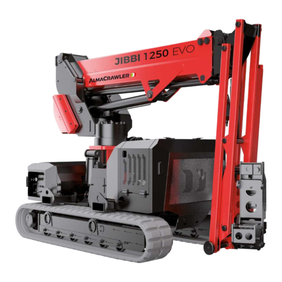
JIBBI is the new crawler
telescopic boom by
JIBBI
AlmaCrawler.
1250 EVO
JIBBI is the new crawler
telescopic boom by
AlmaCrawler.
Patent Pending Innovations
New Dynamic Work Performance (DWP by Almac)
Undercarriage integrated by new Safe-lock System
Patent Pending Innovations
New Dynamic Work Performance (DWP by Almac)
Undercarriage integrated by new Safe-lock System
Cable remote console by AUTEC
Cable remote console by AUTEC
1300 551 108 | info@alfasihire.com.au | alfasihire.com.au
1400
1400
1150
1950
1150
1950
2550
2420
2550
2420
1840
2820
720
3740
1840
2820
720
3740
Mixed slope levelling
Advertisement
Table of Contents

Subscribe to Our Youtube Channel
Related Manuals for ALMACRAWLER JIBBI Series


Summary of Contents for ALMACRAWLER JIBBI Series
- Page 1 2550 1400 2420 2550 1400 2420 JIBBI is the new crawler telescopic boom by JIBBI 1840 1150 2820 AlmaCrawler. 1950 3740 1250 EVO JIBBI is the new crawler telescopic boom by 1840 1150 2820 AlmaCrawler. 1950 3740 Patent Pending Innovations...
- Page 2 Max working height 12,2 m Yanmar Diesel Engine, 3 Cylinders (14,1kW - 19,2 HP) Max height basket floor 10,2 m Yanmar Diesel Engine, 3 Cylinders Max working height 12,2 m 240° Slewing ring rotation Yanmar Diesel Engine, 3 Cylinders Max working height 12,2 m (14,1kW - 19,2 HP) Moving height...
- Page 3 80 kg 120 kg 230 kg 1300 551 108 | info@alfasihire.com.au | alfasihire.com.au...
- Page 4 JIBBI SERIES: JIBBI 1250 - JIBBI 1270 - JIBBI 1670 JIBBI U-1570 USE AND MAINTENANCE ENGLISH Original Instructions ALMAC S.r.l. e-mail: info@almac-italia.com Tel. +39 0375 83 35 27 Fax. +39 0375 78 43 50 Registered office Operational Headquarters Viale Ruggeri 6/A Via Caduti sul Lavoro 1 42016 –...
- Page 5 PAGE2 DATE DESCRIPTION OF THE REVISION 01/08/2022 • First issue of the unified manual document for the whole JIBBI range. • Correction of errors in reduced-track working diagrams: INHIBITED 30/03/2023 TRANSLATION was incorrectly indicated.
-
Page 6: Table Of Contents
PAGE3 SUMMARY GENERAL INFORMATION..................7 ................7 EGULATORY AND LEGAL ASPECTS 1.1.1 Documentation supplied................7 1.1.2 Notification of commissioning, first check, subsequent periodic checks and transfer of ownership......................7 1.1.2.1 Notification of commissioning and first check (only for Italy)............8 1.1.2.2 Periodic checks following the first check. - Page 7 PAGE4 2.4.5.2 JIBBI U-1570 working diagrams with maximum track. Translation allowed........46 2.4.5.3 JIBBI U-1570 working diagrams with reduced track 2.19 m. Translation inhibited......47 2.4.5.4 JIBBI U-1570 working diagrams with reduced track 1.98 m. Translation inhibited......48 2.4.5.5 Working diagrams JIBBI U-1570 with reduced track 1.9 m asymmetrical.
- Page 8 PAGE5 5.1.3.6.6 HORN button......................90 5.1.3.6.7 "MANUAL" function activation button................90 5.1.3.6.8 Safety key (only for RADIO CONTROL version)..............90 5.1.3.6.9 Radio remote control additional battery (only for RADIO CONTROL version)........ 90 5.1.3.6.10 Cable and connector (only for RADIO CONTROL version)............91 5.1.3.6.11 Graphic display and service buttons (versions with DISPLAY).
- Page 9 PAGE6 7.1.3 Emergency recovery with a manual pump............129 7.1.3.1 Operator emergency recovery..................129 7.1.4 Emergency movement of the machine in case of control failure......131 MAINTENANCE....................132 ................. 132 AFETY RULES DURING MAINTENANCE ..................133 RDINARY MAINTENANCE 8.2.1 Cleaning the machine and adhesive plates.
-
Page 10: General Information
PAGE7 1 GENERAL INFORMATION. This document contains proprietary information. All rights reserved. This document cannot be reproduced, in whole or in part, without the prior written consent of ALMAC s.r.l. The use of this document is permitted only to the customer to whom the manual was provided as a kit with the equipment, and only for purposes of use and maintenance of the equipment to which the manual refers. -
Page 11: Notification Of Commissioning And First Check (Only For Italy)
PAGE8 1.1.2.1 Notification of commissioning and first check (only for Italy). In Italy, the owner of the Elevating Work Platform (PLE) must report its commissioning to INAIL and submit it to mandatory periodic checks. The first check is carried out by INAIL within sixty days from the request, after which the employer can make use of the ASLs or authorized public or private entities. -
Page 12: Training, Information And Training Of Operators
PAGE9 1.1.3 Training, information and training of operators. Training, information and training of operators are legal obligations for the employer. The employer must in fact ensure that the workers in charge of the use of the equipment receive adequate and specific training to allow their use in a suitable and safe way, also in relation to the damage that may be caused to other people and things. -
Page 13: Request For Intervention Under Warranty And Technical Assistance
PAGE10 1.1.5.2 Request for intervention under warranty and technical assistance. Any requests for spare parts or technical interventions under warranty must be reported to ALMAC S.r.l. as soon as a defect is found. For any request for assistance, always contact the ALMAC technical assistance service as indicated below: OPERATIONAL REGISTERED OFFICE HEADQUARTERS... -
Page 14: Description And Intended Use Of The Machine
PAGE11 1.2 Description and intended use of the machine. The machine described in this manual is a self-propelled Elevating Work Platform or, as described by the EN280 technical standard, a mobile machine designed to move people to work positions, in which they perform tasks while remaining on the work platform, with the understanding that persons enter and exit the work platform only through access positions at ground or chassis level, and which consists of at least a work platform with controls, an extendable structure (lift arms) and a frame. - Page 15 PAGE12 platform is made of aluminium and is equipped with parapets and toe-boards of regular height (parapets H = 1100 mm; toeboard H = 150 mm). Platforms of various sizes can be installed; see technical data. The levelling of the platform is automatic and is guaranteed by: Master-slave hydraulic system for models JIBBI 1250, JIBBI 1270 and JIBBI 1670;...
-
Page 16: Operating Positions
PAGE13 1.3 Operating positions. The machine control system can be of two types: Control system with wired console on platform (remote control - standard); Control system with console connected via radio on platform (radio control - optional). In both cases, the normal operating position is located on the platform while on the ground there is a control station for the emergency recovery of the platform. -
Page 17: Uses Not Permitted And "Disembarkation At High Altitude
PAGE14 1.5 Uses not permitted and "Disembarkation at high altitude". Normal and permitted use of the machine is described in the previous paragraphs. Anything not described as normal and permitted use is to be considered as not permitted use. It is forbidden to operate the work platform from the ground control station except for emergency recovery operations. -
Page 18: Identification
PAGE15 1.6 Identification. In the event of a request for spare parts and for interventions, the data shown on the registration plate located on the turret or on the identification plate on the platform must always be mentioned. In case of loss or illegibility of the plates (as well as for the various adhesive plates located throughout the machine), it must be restored as quickly as possible. -
Page 19: Definitions And Locations Of The Main Components
PAGE16 1.7 Definitions and locations of the main components The main components of the machine are shown in the following images. This manual deals with different models and equipment so some images may differ slightly from the model owned. 1. Lower frame 2. - Page 20 PAGE17 Specific components for ELC - LTH versions: 1. Lithium (LTH) or pb-acid (ELC) traction batteries 2. 48V electric motor 3. Electric motor 220V / 110V (LTH) or ballast (ELC) 4. Battery charger 5. Electrical box for contractors Figure 3...
-
Page 21: Technical Data, Dimensions And Working Diagrams
PAGE18 2 TECHNICAL DATA, DIMENSIONS AND WORKING DIAGRAMS. 2.1 JIBBI 1250. 2.1.1 General technical data JIBBI 1250. Dimensions: Metric Imperial Maximum working height (1) 12.3 40' 4" Maximum height of the walking surface (1) 10.3 33' 9" Maximum working outreach from slewing bearing centre (1) 22' 7"... -
Page 22: Technical Data Version Jibbi 1250 Evo - Yanmar 3Tnm68-As
PAGE19 2.1.2 Technical data version JIBBI 1250 EVO - YANMAR 3TNM68-AS. Technical data Metric Imperial Diesel engine type: Yanmar 3TNM68-AS Certification STAGE-V Machine weight (1) 2880 6350 Dry mass of the engine Displacement cm³ Net power 14.7 Net power regime 3600 g/min 3600... -
Page 23: Technical Data Version Jibbi 1250 Evo - Yanmar 3Tnv74-Sdsa
PAGE20 2.1.3 Technical data version JIBBI 1250 EVO - YANMAR 3TNV74-SDSA. Technical data Metric Imperial Diesel engine type: Yanmar 3TNV74-SDSA Certification EPA Final Tier 4 - Stage V Machine weight (1) 2880 6350 Dry mass of the engine Displacement cm³ Net power 14.2 Net power regime... -
Page 24: Technical Data Jibbi 1250 Elc Version
PAGE21 2.1.4 Technical data JIBBI 1250 ELC version. Technical data Metric Imperial Lead Acid Battery Machine weight (1) 3575 7880 Battery nominal voltage Battery nominal capacity (c5) Battery weight 1280 Battery size 830 x 520 33 x 21 h = h = 575 Battery Life (4) ≥1500... -
Page 25: Technical Data Jibbi 1250 Lth Version
PAGE22 2.1.5 Technical data JIBBI 1250 LTH version. Technical data Metric Imperial Lithium battery - LiFePO4 Machine weight (1) 2920 6440 Battery nominal voltage Battery nominal capacity Battery weight 780 x 550 h 31 x 22 h = Battery size = 455 Battery Life (4) ≥2000... -
Page 26: Jibbi 1250 Working Diagrams (All Versions - Except Rt)
PAGE23 2.1.6 JIBBI 1250 working diagrams (all versions - except RT). 2.1.6.1 JIBBI 1250 working diagrams at the maximum track. Translation inhibited. Metric Imperial Maximum working height - 230 kg 12.3 40' 4'' Maximum working outreach - 230 kg 17' 5'' Maximum working outreach - 140 kg 20' 0'' Maximum working outreach - 80 kg... - Page 27 PAGE24 Metric Imperial Maximum working height - 140 kg 12.1 39' 8'' Maximum working height - 230 kg 11.9 39' 0'' Maximum working outreach - 230 kg 16' 0'' Maximum working outreach - 140 kg 18' 4'' Maximum working outreach - 80 kg 21' 7''...
-
Page 28: Jibbi 1250 Working Diagrams At The Maximum Track. Translation Allowed
PAGE25 2.1.6.2 JIBBI 1250 working diagrams at the maximum track. Translation allowed. Metric Imperial Maximum working height - 230 kg 22' 0'' Maximum working outreach - 230 kg 14' 1'' Max. angle arm lifting ° ° Max angle jib lifting °... -
Page 29: Jibbi 1250 Working Diagrams With Reduced Track (Capacity 140 Kg). Translation Inhibited
PAGE26 2.1.6.3 JIBBI 1250 working diagrams with reduced track (capacity 140 kg). Translation allowed. Metric Imperial Maximum working height - 140 kg 27' 3'' Maximum working outreach - 140 kg 17' 5'' Max. angle arm lifting ° ° Metric Imperial Maximum working height - 140 kg 29' 2'' Maximum working outreach - 140 kg... -
Page 30: Jibbi 1250 Transport Configuration
PAGE27 2.1.6.4 JIBBI 1250 transport configuration. Metric Imperial Maximum height of the walking 1.62 5' 4'' surface Maximum working height 11' 6''... -
Page 31: Jibbi 1250 Rt
PAGE28 2.2 JIBBI 1250 RT. 2.2.1 General technical data JIBBI 1250 RT. Dimensions: Metric Imperial Maximum working height (1) 12.4 40' 8'' Maximum height of the walking surface (1) 10.4 34' 1'' Maximum working outreach from slewing bearing centre (1) 22' 8'' Maximum platform capacity (m) Maximum number of people on the platform (n) -
Page 32: Technical Data Version Jibbi 1250 Evo-Rt - Yanmar 3Tnm68-As
PAGE29 2.2.2 Technical data version JIBBI 1250 EVO-RT - YANMAR 3TNM68-AS. Metric Imperial Diesel engine type: Yanmar 3TNM68-AS Certification STAGE V Machine weight (1) 2865 6316 Dry mass of the engine Displacement cm³ Net power 14.7 Net power regime 3600 g/min 3600 Engine oil quantity... -
Page 33: Technical Data Version Jibbi 1250 Evo-Rt - Yanmar 3Tnv74-Sdsa
PAGE30 2.2.3 Technical data version JIBBI 1250 EVO-RT - YANMAR 3TNV74-SDSA Metric Imperial Diesel engine type: Yanmar 3TNV74-SDSA Certification EPA Final Tier 4 - Stage V Machine weight (1) 2865 6316 Dry mass of the engine Displacement cm³ Net power 14.2 Net power regime 3000... -
Page 34: Jibbi 1250 Rt Working Diagrams
PAGE31 2.2.4 JIBBI 1250 RT working diagrams. 2.2.4.1 JIBBI 1250 RT working diagrams. Maximum height and maximum outreach. Translation inhibited. Metric Imperial Maximum working height - 140 kg 12.4 40' 8'' Maximum working height - 230 kg 12.1 39' 8'' Maximum working outreach - 230 kg 16' 5'' Maximum working outreach - 140 kg... - Page 35 PAGE32 Metric Imperial Maximum working height - 230 kg 12.3 40' 4'' Maximum working outreach - 230 kg 17' 5'' Maximum working outreach - 140 kg 20' 0'' Maximum working outreach - 80 kg 22' 8'' Metric Imperial Maximum working height - 230 kg 12.3 40' 4'' Maximum working outreach - 230 kg...
-
Page 36: Jibbi 1250 Rt Working Diagrams. Translation Allowed
PAGE33 2.2.4.2 JIBBI 1250 RT working diagrams. Translation allowed. Metric Imperial Maximum working height - 140 kg 28' 3'' Maximum working outreach - 140 kg 17' 5'' Max. angle arm lifting ° ° Metric Imperial Maximum working height - 230 kg 22' 4'' Maximum working outreach - 230 kg 14' 5''... -
Page 37: Jibbi 1250 Rt Transport Configuration
PAGE34 Metric Imperial Maximum working height - 230 kg 22' 4'' Maximum working outreach - 230 kg 14' 9'' Max angle jib lifting ° ° Max. angle arm lifting ° ° 2.2.4.3 JIBBI 1250 RT transport configuration. Metric Imperial Maximum height of the walking 1.73 5' 8'' surface... -
Page 38: Jibbi 1270
PAGE35 2.3 JIBBI 1270 2.3.1 General technical data JIBBI 1270 Dimensions: Metric Imperial Maximum working height (1) 12.3 40' 4" Maximum height of the walking surface (1) 10.3 33' 9" Maximum working outreach from slewing bearing centre (1) 27' 0" Maximum platform capacity (m) Maximum number of people on the platform (n) Mass of equipment and materials on the platform (me) -
Page 39: Technical Data Version Jibbi 1270 Evo - Yanmar 3Tnm68-As
PAGE36 2.3.2 Technical data version JIBBI 1270 EVO - YANMAR 3TNM68-AS Technical data Metric Imperial Diesel engine type: Yanmar 3TNM68-AS Certification STAGE-V Machine weight (1) 3620 7981 Dry mass of the engine Displacement cm³ Net power 14.7 Net power regime 3600 g/min 3600... -
Page 40: Technical Data Version Jibbi 1270 Evo - Yanmar 3Tnv74-Sdsa
PAGE37 2.3.3 Technical data version JIBBI 1270 EVO - YANMAR 3TNV74-SDSA Technical data Metric Imperial Diesel engine type: Yanmar 3TNV74-SDSA Certification EPA Final Tier 4 - Stage V Machine weight (1) 3620 7981 Dry mass of the engine Displacement cm³ Net power 14.2 Net power regime... -
Page 41: Jibbi 1270 Working Diagrams
PAGE38 2.3.4 JIBBI 1270 working diagrams 2.3.4.1 JIBBI 1270 working diagrams with maximum track. Translation inhibited. Metric Imperial Maximum working height 12.3 39' 4'' Maximum working outreach - 230 kg 20' 4'' Maximum working outreach - 140 kg 24' 0'' Maximum working outreach - 80 kg 27' 0'' Metric... -
Page 42: Jibbi 1270 Working Diagrams With Reduced Track. Translation Inhibited
PAGE39 2.3.4.2 JIBBI 1270 working diagrams with reduced track. Translation allowed. Metric Imperial Maximum working height 27' 3'' Maximum working outreach 17' 9'' 2.3.4.3 JIBBI 1270 working diagrams with maximum track. Translation allowed. Metric Imperial Maximum working height 28' 0'' Maximum working outreach 17' 8'' Maximum angle of arm lifting... -
Page 43: Jibbi 1270 Transport Configuration
PAGE40 Metric Imperial A Maximum working height 27' 7'' B Maximum working outreach 17' 9'' C Maximum angle of arm lifting ° ° 2.3.4.4 JIBBI 1270 transport configuration. Metric Imperial A Maximum height of the walking 1.63 5' 4'' surface B Maximum working height 3.63 12' 0''... -
Page 44: Jibbi U-1570
PAGE41 2.4 JIBBI U-1570. 2.4.1 General technical data JIBBI U-1570. Dimensions: Metric Imperial Maximum working height (1) 15.2 50' 0'' Maximum height of the walking surface (1) 13.2 43' 4'' Maximum working outreach from slewing bearing centre (1) 31' 6'' Maximum platform capacity (m) Maximum number of people on the platform (n) Mass of equipment and materials on the platform (me) -
Page 45: Technical Data Version Jibbi U-1570 Evo - Yanmar 3Tnm68-As
PAGE42 2.4.2 Technical data version JIBBI U-1570 EVO - YANMAR 3TNM68-AS. Technical data Metric Imperial Diesel engine type: Yanmar 3TNM68-AS Certification STAGE V Machine weight (1): 2880 6349 Dry mass of the engine Displacement cm³ Net power 14.7 Net power regime 3600 g/min 3600... -
Page 46: Technical Data Version Jibbi U-1570 Evo - Yanmar 3Tnv74-Sdsa
PAGE43 2.4.3 Technical data version JIBBI U-1570 EVO - YANMAR 3TNV74-SDSA. Technical data Metric Imperial Diesel engine type: Yanmar 3TNV74-SDSA Certification EPA Final Tier 4 - Stage V Machine weight (1) 2880 6349 Dry mass of the engine Displacement cm³ Net power 14.2 Net power regime... -
Page 47: Technical Data Jibbi U-1570 Lth Version
PAGE44 2.4.4 Technical data JIBBI U-1570 LTH version. Technical data Metric Imperial Lithium battery - LiFePO4 Machine weight (1) 2935 6471 Battery nominal voltage Battery nominal capacity Battery weight 780 x 550 h 31 x 22 h = Battery size = 455 Battery Life (4) ≥2000... -
Page 48: Jibbi U-1570 Working Diagrams (All Versions)
PAGE45 2.4.5 JIBBI U-1570 working diagrams (all versions). 2.4.5.1 JIBBI U-1570 working diagrams with maximum track. Translation inhibited. Metric Imperial A Maximum working height - 250 kg 15.2 50' 0'' B Maximum working outreach - 250 kg 22' 4'' C Maximum working outreach - 200 kg 24' 0'' D Maximum working outreach - 140 kg 27' 0''... -
Page 49: Jibbi U-1570 Working Diagrams With Maximum Track. Translation Allowed
PAGE46 2.4.5.2 JIBBI U-1570 working diagrams with maximum track. Translation allowed. Metric Imperial A Maximum working height - 250 kg 24' 3'' B Maximum working height - 170 kg 31' 6'' C Maximum working outreach - 250 kg 17' 9'' D Maximum working outreach - 170 kg 22' 0'' E Max. -
Page 50: Jibbi U-1570 Working Diagrams With Reduced Track 2.19 M. Translation Inhibited
PAGE47 2.4.5.3 JIBBI U-1570 working diagrams with reduced track 2.19 m. Translation inhibited. Metric Imperial A Maximum working height - 250 kg 14.2 46' 7'' B Maximum working height - 200 kg 15.2 50' 0'' C Maximum working outreach - 250 kg 20' 0'' D Maximum working outreach - 200 kg 21' 8''... -
Page 51: Jibbi U-1570 Working Diagrams With Reduced Track 1.98 M. Translation Inhibited
PAGE48 2.4.5.4 JIBBI U-1570 working diagrams with reduced track 1.98 m. Translation inhibited. Metric Imperial A Maximum working height - 250 kg 12.9 42' 4'' B Maximum working height - 200 kg 13.9 45' 7'' C Maximum working height - 140 kg 15.2 50' 0'' D Maximum working outreach - 250 kg... -
Page 52: Working Diagrams Jibbi U-1570 With Reduced Track 1.9 M Asymmetrical. Translation Inhibited
PAGE49 2.4.5.5 Working diagrams JIBBI U-1570 with reduced track 1.9 m asymmetrical. Translation inhibited. Metric Imperial A Maximum working height - 250 kg 10.3 33' 9'' B Maximum working height - 200 kg 11.0 36' 0'' C Maximum working height - 140 kg 12.1 39' 8'' D Maximum working height - 140 kg... -
Page 53: Jibbi U-1570 Working Diagrams With Reduced Track (1.35 M). Translation Inhibited
PAGE50 2.4.5.6 JIBBI U-1570 working diagrams with reduced track (1.35 m). Translation allowed. Metric Imperial A Maximum working height - 250 kg 25' 7'' B Maximum working height - 200 kg 29' 2'' C Maximum working height - 170 kg 30' 6'' D Maximum working outreach - 250 kg 20' 0''... -
Page 54: Jibbi U-1570 Transport Configuration
PAGE51 2.4.5.7 JIBBI U-1570 transport configuration. Metric Imperial Maximum height of the walking 1.71 5' 7'' surface M Maximum working height 3.71 12' 2''... -
Page 55: Jibbi 1670
PAGE52 2.5 JIBBI 1670. 2.5.1 General technical data JIBBI 1670. Dimensions: Metric Imperial Maximum working height (1) 16.0 52' 6'' Maximum height of the walking surface (1) 14.0 46' 0'' Maximum working outreach from slewing bearing centre (1) 27' 7'' Maximum platform capacity (m) Maximum number of people on the platform (n) Mass of equipment and materials on the platform (me) -
Page 56: Technical Data Version Jibbi 1670 Evo - Yanmar 3Tnm68-As
PAGE53 2.5.2 Technical data version JIBBI 1670 EVO - YANMAR 3TNM68-AS. Technical data Metric Imperial Diesel engine type: Yanmar 3TNM68-AS Certification STAGE V Machine weight (1) 3850 8488 Dry mass of the engine Displacement cm³ Net power 14.7 Net power regime 3600 g/min 3600... -
Page 57: Technical Data Version Jibbi 1670 Evo - Yanmar 3Tnv74-Sdsa
PAGE54 2.5.3 Technical data version JIBBI 1670 EVO - YANMAR 3TNV74-SDSA. Technical data Metric Imperial Diesel engine type: Yanmar 3TNV74-SDSA Certification EPA Final Tier 4 - Stage V Machine weight (1) 3850 8488 Dry mass of the engine Displacement cm³ Net power 14.2 Net power regime... -
Page 58: Technical Data Jibbi 1670 Lth Version
PAGE55 2.5.4 Technical data JIBBI 1670 LTH version. Metric Imperial Lithium battery - LiFePO4 Machine weight (1) 3880 8554 Battery nominal voltage Battery nominal capacity Battery weight 780 x 550 h 31 x 22 Battery size = 455 h = 18 Battery Life (4) ≥2000 cycles... -
Page 59: Jibbi 1670 Working Diagrams (All Versions)
PAGE56 2.5.5 JIBBI 1670 working diagrams (all versions). 2.5.5.1 JIBBI 1670 working diagrams with maximum track (2.45 m). Translation inhibited. Metric Imperial A Maximum working height - 230 kg 16.0 52' 6'' B Maximum working outreach - 230 kg 21' 8'' C Maximum working outreach - 140 kg 24' 7'' D Maximum working outreach - 80 kg... -
Page 60: Jibbi 1670 Working Diagrams With Maximum Track (2.45 M). Translation Allowed
PAGE57 2.5.5.2 JIBBI 1670 working diagrams with maximum track (2.45 m). Translation allowed. Metric Imperial A Maximum working height - 230 kg 32' 0'' B Maximum working outreach - 230 kg 22' 0'' C Max. angle arm lifting ° ° Metric Imperial A Maximum working height - 230 kg... -
Page 61: Jibbi 1670 Working Diagrams With Reduced Track 2.19 M. Translation Inhibited
PAGE58 2.5.5.3 JIBBI 1670 working diagrams with reduced track 2.19 m. Translation inhibited. Metric Imperial A Maximum working height - 230 kg 15.8 52' 0'' B Maximum working outreach - 230 kg 21' 8'' C Maximum working outreach - 140 kg 24' 7'' D Maximum working outreach - 80 kg 27' 7''... - Page 62 PAGE59 Metric Imperial A Maximum working height - 230 kg 15.5 51' 0'' B Maximum working height - 140 kg 15.9 52' 2'' C Maximum working outreach - 230 kg 19' 4'' D Maximum working outreach - 140 kg 23' 4'' E Maximum working outreach - 80 kg 25' 7''...
-
Page 63: Jibbi 1670 Working Diagrams With Reduced Track 1.9 M. Translation Inhibited
PAGE60 2.5.5.4 JIBBI 1670 working diagrams with reduced track 1.9 m. Translation inhibited. Metric Imperial A Maximum working height - 230 kg 15.1 49' 6'' B Maximum working height - 140 kg 16.0 52' 6'' C Maximum working outreach - 230 kg 21' 8'' D Maximum working outreach - 140 kg 22' 4''... - Page 64 PAGE61 Metric Imperial A Maximum working height - 230 kg 12.6 41' 4'' B Maximum working height - 140 kg 13.7 45' 0'' C Maximum working height - 80 kg 15.1 49' 6'' D Maximum working outreach - 230 kg 21' 8'' E Maximum working outreach - 80 kg 22' 4''...
-
Page 65: Jibbi 1670 Working Diagrams With Reduced Track 1.9 M Asymmetrical. Translation Inhibited
PAGE62 2.5.5.5 JIBBI 1670 working diagrams with reduced track 1.9 m asymmetrical. Translation inhibited. Metric Imperial A Maximum working height - 230 kg 11.1 36' 5'' B Maximum working height - 140 kg 12.3 40' 4'' C Maximum working height - 80 kg 13.2 43' 4'' D Maximum working outreach - 230 kg... -
Page 66: Jibbi 1670 Working Diagrams With Reduced Track (1.35 M). Translation Inhibited
PAGE63 2.5.5.6 JIBBI 1670 working diagrams with reduced track (1.35 m). Translation allowed. Metric Imperial A Maximum working height - 230 kg 31' 0'' B Maximum working outreach - 230 kg 21' 8'' C Max. angle arm lifting ° ° Metric Imperial A Maximum working height - 230 kg... -
Page 67: Jibbi 1670 Transport Configuration
PAGE64 2.5.5.7 JIBBI 1670 transport configuration. Metric Imperial Maximum height of the walking 1.89 6' 2'' surface M Maximum working height 3.89 12' 9''... -
Page 68: Safety Information, Obligations And Prohibitions
PAGE65 3 SAFETY INFORMATION, OBLIGATIONS AND PROHIBITIONS. 3.1 Personal Protective Equipment (PPE). For completely safe use of the machine it is mandatory to wear the appropriate Personal Protective Equipment indicated below, in addition to any additional devices related to the risks connected to the activity carried out to be identified by the Employer (example: in cases of activities in a noisy environment, the use of hearing protectors, etc. -
Page 69: Safety Rules
PAGE66 3.2 Safety rules. 3.2.1 General safety rules. • Read this manual carefully before proceeding with start-up, use, maintenance or other interventions on the machine; • The use of the machine is reserved for adults (18 years of age) and adequately instructed and trained; •... - Page 70 PAGE67 • It is forbidden to operate the PLE from the ground control position when the operators are present on the platform, except for emergency recovery operations; • It is forbidden to transport large materials or panels, as they increase wind resistance, causing a strong risk of overturning.
-
Page 71: Handling And Displacements
PAGE68 3.2.2 Handling and displacements • It is forbidden to drive on roads open to traffic. The machine is not approved for this purpose. • Do not operate on soft ground to avoid the risk of instability and machine downtime. To avoid overturning, it is necessary to comply with the maximum permissible slopes indicated in the chapter relating to the technical characteristics of each model under the heading “Stability limits”;... -
Page 72: Stages Of Work
PAGE69 Figure 5 3.2.3 Stages of work. • The machine is equipped with numerous sensors on its moving parts (extendable tracks, arms, rotations, telescopic extension, etc.) which constantly monitor the configuration of the machine and the loads transported on the platform. Any alarms or manoeuvre inhibitions are clearly indicated on the display of the platform control console (or by luminous LEDs for consoles without display);... - Page 73 PAGE70 Figure 6...
-
Page 74: Wind Action And Beaufort Scale
PAGE71 3.2.4 Wind action and Beaufort scale. The wind is one of the possible causes of overturning. Use of the machine with winds exceeding 12.5 m / s (45 km / h - 28 mph) is prohibited. There is no anemometer on the standard machine; to monitor the wind speed, refer to the table below, where the operating wind limit is defined as N.6 according to the BEAUFORT INTERNATIONAL SCALE. -
Page 75: Ground Suitability And Pressure To The Ground Of The Machine
PAGE72 3.2.5 Ground suitability and pressure to the ground of the machine. 3.2.5.1 Bearing capacity of the ground. Always, before using the machine, the operator must check that the floor or ground is suitable to withstand the load and pressures generated by the machine, and such as not to slide the machine due to high slope and / or poor grip. - Page 76 PAGE73 EXAMPLE: JIBBI 1270 EVO P1 = 3.685 kg P2 = 2,900 kg M = 230 kg i1 = 183 cm i2 = 383 cm i3 = 46 cm c1 = 195 cm c2 = 25 cm A1 = c1 × i2 = 195 × 383 = 74,685 cm² A2 = c2 ×...
-
Page 77: Ground Inclination
PAGE74 The following table shows the indicative bearing capacity of the soil according to the type of soil. Compare the bearing capacity of the ground with the specific pressure data calculated with the method just described, to understand if the ground is able to withstand the pressure generated by the machine. The values in the table are indicative, therefore in case of doubts the bearing capacity of the ground must be ascertained with specific tests. -
Page 78: Live Power Lines
PAGE75 3.2.6 Live power lines The machine is not electrically isolated and does not provide protection from contact or proximity to electrical lines. It is mandatory to maintain a minimum distance from the electrical lines in accordance with the regulations in force and according to the following table. Minimum distance Type of power lines Voltage (KV) -
Page 79: Installation And Preliminary Checks
PAGE76 4 INSTALLATION AND PRELIMINARY CHECKS. The machine is generally delivered completely assembled, therefore it can perform all the functions provided by the manufacturer in complete safety. There is no need to perform any preliminary operations. To unload the machine, follow the instructions in the "handling and transport" chapter. Place the machine on a sufficiently consistent surface with a slope lower than the maximum allowed (see technical characteristics "Stability limits") before operating it. -
Page 80: Defects Found During Pre-Use Checks
PAGE77 ▪ Check, when used as a platform, that the work platform (basket) is correctly interlocked and that the appropriate warning light on the console signals the "work platform" mode. ▪ Check, when used as a winch (optional), that the winch is correctly interlocked and that the appropriate warning light on the console signals the "Winch"... -
Page 81: Method Of Use
PAGE78 5 METHOD OF USE. 5.1 Control panel on the platform. The platform is equipped with a removable control panel (console) which can be of two types: Remote controller Radio controller Regardless of the type of control system (remote control or radio control), it is possible to remove the control console from the platform, and drive the machine on foot when placing the machine or for loading and unloading the machine from the means of transport. -
Page 82: Fixing The Push-Button Panel On The Platform
PAGE79 5.1.2 Fixing the push-button panel on the platform. When operating from the command station on the platform, or when transporting the machine, it is necessary to fix the mobile push-button panel on the platform following the instructions below: 1. Open the lid by pulling the side piston indicated by the arrow outwards;... -
Page 83: Platform Push-Button Panel With Graphic Display
PAGE80 5.1.3 Platform push-button panel with GRAPHIC DISPLAY. Figure 11 1. LEFT MULTIFUNCTION JOYSTICK: a. LEFT CRAWLER DRIVE / LEFT TRACK (ORANGE) b. ARM / TURRET ROTATION (LIGHT BLUE) c. MANUAL (GREEN) 2. RIGHT MULTIFUNCTION JOYSTICK: a. RIGHT CRAWLER DRIVE / RIGHT TRACK (ORANGE) b. -
Page 84: Dead Man" System
PAGE81 5.1.3.1 "Dead man" system. For safety reasons, when turning on the machine, after activating the EMERGENCY STOP button (3) by turning it clockwise, to have the commands available on the console, press the START button (13) to: Turn on the radio control and activate data transmission (radio control version only); Activate the console commands. -
Page 85: Traction, Steering And Track Widening Controls
PAGE82 5.1.3.2 Traction, steering and track widening controls. Attention: before carrying out any operation to move the machine, check that there are no people in the vicinity or in the range of action of the machine. In any case, proceed with the utmost caution. Before carrying out a traction movement with the platform raised, be sure that the ground on which you intend to move has the characteristics described in the previous paragraphs. -
Page 86: Traction And Steering Control With Dynamic & Proactive Levelling Function
PAGE83 5.1.3.2.1 Traction and steering control with DYNAMIC & PROACTIVE LEVELLING function. The DYNAMIC & PROACTIVE LEVELLING functions are controlled by the selector (5). These automatic functions allow you to operate safely on land whose slope changes gradually. The system is able to compensate for a maximum inclination of 15°... -
Page 87: Traction And Steering Control With Fast Drive And Booster Function
PAGE84 5.1.3.2.2 Traction and steering control with FAST DRIVE and BOOSTER function. The FAST DRIVE and BOOSTER functions are controlled by the button (11). These automatic functions allow you to move at high speed and / or in straight-line travel, by activating only the right control joystick (2). -
Page 88: Manual Control Of The Levelling Of The Fifth Wheel Plane
PAGE85 5.1.3.2.2.2 FAST DRIVE and BOOSTER: OPTIONAL configuration. When the button (11) is pressed, automatic activation of the horn signals that the function has been activated (1 blow of the horn) or deactivated (2 blows of the horn). If the machine is in TRANSPORT CONFIGURATION, regardless of the position of the potentiometer (7), the FAST DRIVE + BOOSTER function is active and: Control the traction with only the right joystick (2) activated within about 90% of its stroke: o the... -
Page 89: Platform Handling (Ascents, Descents, Rotations)
PAGE86 5.1.3.4 Platform handling (ascents, descents, rotations). To move the platform (ascents, descents, rotations), the joysticks (1), (2), the switch (9) and the selector (6) are used. If you are in a condition in which the platform movement commands available (see indications on the DISPLAY / LEDs), once the commands have been activated using the START... -
Page 90: Extension / Retraction Of The Telescopic Arm
PAGE87 In the TRANSPORT position, the turret rotation control stops automatically when it reaches the central position (0° +/- 2°), in order to enable the TRACKS NARROWING command. To continue with the manoeuvre, the proportional joystick (1) must be released and reactivated. 5.1.3.4.3 Extension / retraction of the telescopic arm. -
Page 91: Winch Control (Optional)
PAGE88 when the rotation plane of the fifth wheel is horizontal, the platform movement command is activated. Attention: RISK OF OVERTURNING The system is not able to level the rotation plane of the fifth wheel if the ground is inclined over 15° and, if the selector (5) is in the ON position, it is not possible to carry out any command to move the platform. -
Page 92: Other Functions And Devices Of The Control Panel
PAGE89 5.1.3.6 Other functions and devices of the control panel. 5.1.3.6.1 Emergency stop. Pressing the red emergency stop button (3) instantly stops all functions and the machine switches off. To resume normal functions after pressing the emergency stop button, it is necessary to: Rotate the button clockwise by a quarter of a turn (or pulling outwards, depending on the type of button);... -
Page 93: Start Button
PAGE90 5.1.3.6.5 START button. The START button (13) is used to activate the controls of the push-button panel when the machine is switched on when the message PRESS START appears on the display after the acoustic warning signal has been activated, which signals that the control system has been switched on. 5.1.3.6.6 HORN button. -
Page 94: Cable And Connector (Only For Radio Control Version)
PAGE91 5.1.3.6.10 Cable and connector (only for RADIO CONTROL version). The cable (18) is supplied with the machines equipped with radio control. It is used to physically connect the push-button panel to the machine control system via the connector (16) in case of problems with the radio transmission and for all those occasions in which the use of radio control is not allowed due to specific regulations. -
Page 95: Graphic Display And Service Buttons (Versions With Display)
PAGE92 5.1.3.6.11 Graphic display and service buttons (versions with DISPLAY). On the graphic display (21) there is information necessary during normal use of the machine on the graphic part of the display and in the area of the warning lights (19). There is also information needed during service interventions, for information on errors and diagnostics, using the service... - Page 96 PAGE93 5.1.3.6.11.1 Main screen indications. Green indicator: “Fuel OK” - “Batt. OK ”Fuel / Battery level Fuel Fuel / Battery level sufficient; indicator Red indicator: “Fuel reserve” - Battery “Low battery %” Fuel level / Low battery. Green indicator: “BOOSTER ON” Booster active;...
- Page 97 PAGE94 Note: These conditions, if they restrict movement, are highlighted in the alarm box. It updates in real time the maximum outreach that the operator can reach with respect to the centre of the fifth wheel, according working Limit outreach diagram.
- Page 98 PAGE95 : N°4 Arrows: EXTENDED TRACK. The track is at the end of its travel. N.B .: Depending on the track, the machine automatically adjusts possible working diagrams also based on the load on the platform. All crawler extension steps are also signalled with an acoustic signal.
- Page 99 PAGE96 5.1.3.6.11.2 Brightness adjustment button (A). Press this button several times to adjust different brightness of the display. 5.1.3.6.11.3 HOME button (B). Press this key to return to the main display screen. 5.1.3.6.11.4 ERRORS button (C). Press this key to enter the ERROR LIST screen, where any errors in progress are displayed. Selecting the ERROR LOG page, you enter the memory of the recorded errors.
- Page 100 PAGE97 5.1.3.6.11.8 Warning lights. Figure 15 Steady green light: the platform is correctly installed on the machine. In the absence of other alarms, all commands are enabled. On with flashing green light (only for machines with radio control): the push-button panel (radio control) is not located in the platform control station.
- Page 101 PAGE98 If the platform is beyond the transport position but at a height where it is still possible to control the translation: Alarm due to inclination of the fifth wheel plane greater than 1°; the PRO-ACTIVE LEVELLING function is allowed. Steady red light: the platform has reached the maximum outreach allowed for the specific condition of the machine (track width, load on the platform, position of the turntable).
-
Page 102: Platform Push-Button Panel With Led Display
PAGE99 5.1.4 Platform push-button panel with LED DISPLAY. Figure 16 1. LEFT TRACK CONTROL JOYSTICK 2. RIGHT TRACK CONTROL JOYSTICK 3. ARM CONTROL JOYSTICK 4. TELESCOPIC CONTROL JOYSTICK 5. TURRET ROTATION CONTROL JOYSTICK 6. JIB CONTROL SWITCH 7. PLATFORM ROTATION CONTROL SWITCH 8. -
Page 103: Dead Man" System
PAGE100 5.1.4.1 "Dead man" system. For safety reasons, when turning on the machine, after activating the EMERGENCY STOP button (11) by turning it clockwise, to have the commands available on the console, press the START button (17) to: Turn on the radio control and activate data transmission (radio control version only); Activate the console commands. -
Page 104: Traction, Steering And Track Widening Controls
PAGE101 5.1.4.2 Traction, steering and track widening controls. Attention: before carrying out any operation to move the machine, check that there are no people in the vicinity or in the range of action of the machine. In any case, proceed with the utmost caution. Before carrying out a traction movement with the platform raised, be sure that the ground on which you intend to move has the characteristics described in the previous paragraphs. -
Page 105: Traction And Steering Control With Fast Drive And Booster Function
PAGE102 Attention: RISK OF OVERTURNING The system cannot prevent the machine from overturning in the event of sudden changes in the slope of the ground or curbs. It is strictly forbidden to face sudden changes in slope, curbs, dips, holes or bumps in translation. It is the operator's full responsibility to check the suitability of the terrain on which he must move. -
Page 106: Platform Handling (Ascents, Descents, Rotations)
PAGE103 5.1.4.3 Platform handling (ascents, descents, rotations). To move the platform (ascents, descents, rotations) use the joysticks (3), (4) (5), and the switches (6), (7). If you are in a condition in which the platform movement commands available (see indications of the LEDs), once the commands have been activated using the START button (17), it is possible to command the movement of the platform as indicated in the following paragraphs. -
Page 107: Rotation Of The Platform
PAGE104 Only for JIBBI 12xx and JIBBI 16xx: Up or down of the jib (switch 6). 5.1.4.3.4 Rotation of the platform. To perform the platform rotation manoeuvre, the switch (7) is used by operating it to the left to obtain clockwise rotation, or to the right to obtain counterclockwise rotation. -
Page 108: Winch Control (Optional)
PAGE105 5.1.4.4 Winch control (optional). Except for the JIBBI U-1570 model, on the other JIBBI 12xx and JIBBI16xx models, it is possible to install, as INTERCHANGEABLE EQUIPMENT, a winch in place of the platform, allowing the machine to be used as a crane for loads up to 200 kg. -
Page 109: Other Functions And Devices Of The Control Panel
PAGE106 5.1.4.5 Other functions and devices of the control panel. 5.1.4.5.1 Emergency stop. Pressing the red emergency stop button (11) instantly stops all functions and shuts down the machine. To resume normal functions after pressing the emergency stop button, it is necessary to: Rotate the button clockwise by a quarter of a turn (or pulling outwards, depending on the type of button);... -
Page 110: Safety Key (Only For Radio Control Version)
PAGE107 5.1.4.5.6 Safety key (only for RADIO CONTROL version). The safety key (19) is used to activate the control panel. Insert the supplied key to activate the push button panel. If the key is not inserted, the push button panel will not be activated. The key is coded, therefore use only the supplied key;... - Page 111 PAGE108 Function and Identification Function description State Steady green LED: The machine is in transport conditions; TRANSPORT Led off: The machine is not within the transport conditions. Steady green LED: Translation with the machine in transport configuration; Flashing green LED: In addition to the transport DRIVE condition, machine...
- Page 112 PAGE109 Function and Identification Function description State A steady green LED: The movement shown is enabled; Movement Led off: The movement shown is disabled; indication lights Flashing green led: Movement is suggested. Indicator lights relating to the Refer to the remote control manual. operating and battery status of the radio control...
- Page 113 PAGE110 Function and Identification Function description State Steady red LED: Overload exceeded; Flashing red LED: Overload at maximum limit; Led off: Load below the maximum limit. Overload warning light Steady red LED: Maximum outreach has been reached; Flashing red LED: The pre-alarm threshold is entered;...
- Page 114 PAGE111 Jib angle sensor redundancy error; No signal from Jib angle sensor 1; No signal from Jib angle sensor 2. Identification Function description Basket angle sensor redundancy error; No signal from basket angle sensor 1; No signal from basket angle sensor 2. Basket load sensor redundancy error;...
- Page 115 PAGE112 Low Battery Percentage / Low Fuel Level Warning: The errors are listed in order of danger; if two errors occur, the one considered more serious is displayed.
-
Page 116: Operator Anti-Crushing Kit (Optional)
PAGE113 5.1.5 Operator anti-crushing kit (OPTIONAL). As an option, it is possible to install an ultrasonic sensor in the upper part of the platform, as shown in the figure. This accessory, adjusted in the factory, detects obstacles at a vertical distance of fewer than 1.5 m from the handrail and warns the operator of the danger of crushing by means of an appropriate warning on the control push-button panel as well as... -
Page 117: Control Station On The Ground
PAGE114 5.2 Control station on the ground. The ground control station is located on the base carriage. It contains the electronic control unit that manages all the functions of the machine and has the function of: Turn the machine on and off; Select the enabled control station (on the ground or on the platform);... -
Page 118: Main Key Switch / Control Station Selector
PAGE115 8. TURRET ROTATION SWITCH 9. TELESCOPIC RELEASE / RETURN SWITCH 10. ARM UP / DOWN SWITCH 11. JIB UP / DOWN SWITCH 12. PLATFORM ROTATION SWITCH 13. PLATFORM LEVELLING CORRECTION SWITCH 14. HOUR COUNTER 5.2.1 Main key switch / control station selector. The main key of the ground control station is used to: Switch on the machine by selecting one of the two control stations: Control station on the platform with the key turned on the BLUE frame. -
Page 119: Emergency Stop Button
PAGE116 5.2.3 Emergency stop button. Press the button to completely stop the machine and the engine. To resume normal operation of the machine - depending on the position of the key selector - it is necessary to turn the button a quarter of a turn clockwise so that the button is completely extracted. -
Page 120: Connector For Use With Winch Kit (Optional)
PAGE117 5.2.6 Connector for use with winch kit (OPTIONAL). It is possible to connect to the ground control panel with the cable console only when the WINCH KIT (Optional) is installed and the key switch is turned to the PURPLE position. If the machine is supplied with a REMOTE CONTROL (optional), the WINCH KIT can only be used if the key selector is in the BLUE position. -
Page 121: Access To The Platform
PAGE118 5.3 Access to the platform. The access position is the only position in which the boarding and disembarkation of people and materials from the platform is allowed. Procedure to access the platform: Lift the inlet rod (1); With the help of the uprights, climb onto the platform (2);... -
Page 122: Starting The Machine
PAGE119 5.4 Starting the machine. To start the machine, the operator must: Release ground control station emergency stop button (2) by turning it clockwise by a quarter of a turn; Turn the key selector (1) of the ground control station, bringing it to the position represented by the blue box (platform controls);... -
Page 123: Starting The Single-Phase Thermal Or Electric Engine (Evo Versions)
PAGE120 5.4.1 Starting the single-phase thermal or electric engine (EVO versions) For EVO versions it is now possible to operate the machine using the thermal engine or the single-phase electric motor (if present) on the basis of the instructions in the previous chapters. Check the fuel level before operating the thermal engine. -
Page 124: Stopping The Machine
PAGE121 5.5 Stopping the machine. 5.5.1 Normal shutdown. During normal use of the machine, releasing the joysticks and switches stops the relative command. 5.5.2 Emergency stop. In case of need, the operator can command the emergency stop of the machine both from the platform control panel and from the ground control station by pressing one of the red emergency buttons presents (see image on the side). - Page 125 PAGE122 It is the operator's responsibility to park the machine in a safe place protected against unauthorized use, leaving the machine completely off and removing the main key.
-
Page 126: Removing And Replacing The Platform / Winch
PAGE123 5.7 Removing and replacing the platform / winch. The machines can accommodate different types of platforms or a winch (only machines prepared) to be used for lifting materials. It is also possible to quickly remove the platform to pass with the machine in confined spaces, or for transport needs. -
Page 127: Loading And Transport
PAGE124 6 LOADING AND TRANSPORT. Before transporting the machine between different workplaces with a means of transport, it is necessary to find out about the overall dimensions and the transportable mass limits, on the basis of the road traffic regulations in force. To reduce the transport dimensions of the machine, the platform can be removed (see instructions in the previous chapters). -
Page 128: Transport Length Reduction
PAGE125 6.2 Loading with loading ramp. It is possible to load the machine on the platform of the means of transport by means of loading ramps, using the normal translation controls and driving the machine from the platform control post (see the chapter describing the controls). -
Page 129: Loading With A Crane
PAGE126 6.4 Loading with a crane. It is possible to load the machine on the platform of the means of transport using a crane. By means of four lifting bands or chains of appropriate length and capacity (see the weight of the machine in the TECHNICAL DATA chapter), hooking to the lifting points indicated by the adhesive plates placed on the machine and shown alongside. -
Page 130: Emergency Commands
PAGE127 7 EMERGENCY COMMANDS. While using the emergency controls, a qualified operator, who must always be present on the ground, assumes responsibility for moving the machine and the operator on board using the emergency modes described below. The operator using the emergency controls must always check that the machine movements take place in accordance with the commands activated. -
Page 131: Emergency Recovery Of The Incapacitated Operator In The Presence Of An Overload Alarm
PAGE128 7.1.2 Emergency recovery of the incapacitated operator in the presence of an overload alarm. In the event that the operator on the platform is unable to return to the ground by using the platform controls and with the simultaneous presence of an overload alarm, the machine is blocked. A qualified operator, in possession of the master key (for AUSTRALIA and NEW ZEALAND machines the key is always present on the key selector), can activate the emergency controls of the ground control station. -
Page 132: Emergency Recovery With A Manual Pump
PAGE129 7.1.3 Emergency recovery with a manual pump. 7.1.3.1 Operator emergency recovery. In the event of a power failure, to recover a blocked operator, a qualified operator on the ground must use the manual controls activated by the manual pump in the manner described below. The manual emergency controls are located on the rotating turret: 1. - Page 133 PAGE130 Figure 36 RISK OF OVERTURNING! While using the emergency controls with a manual pump, all safety functions are disabled. The operator on the ground must therefore re-enter with the telescopic arm, then completely lower the jib before activating other movements. Activate only one command at a time.
-
Page 134: Emergency Movement Of The Machine In Case Of Control Failure
PAGE131 7.1.4 Emergency movement of the machine in case of control failure. In the event of a fault in the control system, but with the heat engine (or the single-phase electric pump) still running, it is possible in an emergency to make short movements of the machine (control of the tracks) by manually activating the travel control solenoid valves. -
Page 135: Maintenance
PAGE132 8 MAINTENANCE. 8.1 Safety rules during maintenance. Always carry out maintenance operations in conditions of maximum safety, with the machine stopped and off, having extracted the key from the control panel on the ground, with the emergency buttons pressed and wearing the individual protection devices suitable for the operations to be performed. Only adequately trained personnel are authorized to carry out repairs and maintenance on the machine. -
Page 136: Ordinary Maintenance
PAGE133 8.2 Ordinary maintenance. Checks and maintenance must be carried out as indicated in the table below. PERIODIC TABLE OF ORDINARY MAINTENANCE Machine cleaning Cleaning of plates and warning lights Functional checks Visual check tightening of screws / Tightening of screws Visual inspection of the structural elements of the machine Greasing joints, telescopic extensions and slewing ring Check the hydraulic oil level... - Page 137 PAGE134 The machines can be equipped with different types of heat engines. For routine maintenance operations and for the intervals for interventions on heat engines, always refer to the OPERATION AND MAINTENANCE manual of the engine manufacturer, supplied at the time of delivery of the machine.
-
Page 138: Cleaning The Machine And Adhesive Plates
PAGE135 8.2.1 Cleaning the machine and adhesive plates. To clean the machine properly, you can use non-pressurized water jets, adequately protecting the following details: Electrical components; Ground control panel and console; Electric motor (if present). After cleaning the machine, dry all the details, check the integrity of the adhesive plates and grease the areas with grease nipples or the sliding pads of the telescopic appendages of the arms and stabilizers. - Page 139 PAGE136 Activate the emergency button on the remote control (or radio control), and check that the platform control console and the heat engine (EVO, ETS versions) turn off. Release the emergency button at the end of this test. Activate the emergency button of the ground control station, and check that the machine is completely off and that no function is allowed.
-
Page 140: Visual Inspection Of The Structural Elements Of The Machine
PAGE137 8.2.3 Visual inspection of the structural elements of the machine. According to the periodicity described in the maintenance table, and always before each use of the machine, it is necessary to visually check the integrity of the main structural elements of the machine, with particular attention to the welds. -
Page 141: Visual Check Screw Tightness / Screw Tightening
PAGE138 8.2.4 Visual check screw tightness / Screw tightening. According to the periodicity described in the maintenance table, and always before each use of the machine, it is necessary to visually check the tightening of the elements indicated alongside, i.e.: 1. -
Page 142: Greasing Joints, Telescopic Extensions And Slewing Ring
PAGE139 8.2.5 Greasing joints, telescopic extensions and slewing ring. According to the periodicity described in the maintenance table, proceed with greasing the points equipped with grease nipples and the telescopic appendages indicated in the image alongside. To grease the telescopic arms, fully extend the extensions (with the jib completely closed, and no load on the platform) by raising the arm slightly to avoid interference between the basket and the... -
Page 143: Hydraulic Oil Level Check / Oil Change
PAGE140 8.2.6 Hydraulic oil level check / oil change. According to the periodicity described in the maintenance table, and always before each use of the machine, it is necessary to check the level of hydraulic oil in the tank, through the visual indicator indicated alongside (A). The level check must be performed with: Minimum track (narrow carriage);... - Page 144 PAGE141 According to the periodicity described in the maintenance table, it is necessary to replace the hydraulic oil filters of the suction and return circuits, simultaneously with the replacement of the hydraulic oil. To replace the suction filters (A) located inside the hydraulic tank and the filter cartridge (B) of the return filter (C) in the same operation: Turn off the machine completely;...
-
Page 145: Traction Reduction Gear Oil Level Check / Oil Change
PAGE142 8.2.8 Traction reduction gear oil level check / oil change. According to the periodicity described in the maintenance table, it is necessary to check the oil level in the traction reducers according to the following procedure. To check the level: command the translation until the plugs (A) and (B) are in the position shown alongside;... -
Page 146: Tracks: Check For Wear, Tensioning And Replacement
PAGE143 8.2.9 Tracks: check for wear, tensioning and replacement. According to the periodicity described in the maintenance table, and always before each use of the machine, it is necessary to check the state of wear and the correct tensioning of the tracks. 8.2.9.1 Track wear check. - Page 147 PAGE144 Once the track is perfectly in place, tighten the track tensioner valve and fill the track tensioner cylinder with grease using the adjustable grease nipple (4) until the correct track tension is obtained; Check the tension as described above, and clean from grease residues. Warning: The replacement of the tracks must be carried out by specialized and adequately trained personnel.
-
Page 148: Extension Chains: Wear Control, Tensioning And Lubrication
PAGE145 8.2.10 Extension chains: Wear control, Tensioning and Lubrication. According to the periodicity described in the maintenance table, check the extension chains: Wear control; Tension control; Lubrication. 8.2.10.1 Chain wear check. The wear control of the telescopic extension / retraction chains consists mainly of measuring a 10-step stretch and evaluating the percentage elongation. -
Page 149: Chain Lubrication
PAGE146 8.2.10.3 Chain lubrication. The extension / return chains must always be kept lubricated. Lubricate the extension / return chains according to the frequency described in the maintenance table. For correct lubrication it is necessary: Remove the telescopic arm in safety conditions (machine on flat ground, in stable conditions, without load on the platform and with the jib completely retracted);... -
Page 150: Turret Rotation Game Control
PAGE147 8.2.12 Turret rotation game control. According to the periodicity described in the maintenance table, check the play of the turret rotation system. The turret rotation system used on ALMAC machines makes it possible to have no play at the base of the rotating turret by applying horizontal forces to the platform. -
Page 151: Overload Control Device Check
PAGE148 8.2.14 Overload control device check. According to the periodicity described in the maintenance table, check the operation of the platform overload control system. The work platform support incorporates a sensor that detects the load present on the platform. If the rated load is exceeded by 20% of the rated load, and the platform is not in the access position, the overload alarm is activated and the machine is completely blocked. -
Page 152: Check The Efficiency Of The Differential Switch 115-220V Socket
PAGE149 8.2.15 Check the efficiency of the differential switch 115-220V socket. According to the frequency described in the maintenance table, check the operation of the differential switch of the power line on the platform To verify its operation: Connect the plug located on the base frame to a cable connected to the mains in compliance with current regulations;... -
Page 153: Battery
PAGE150 8.2.18 Battery. The battery is a component of fundamental importance in the operation of the machine. Maintaining it over time is important to both increase its life, but also to limit problems and reduce the operating costs of the machine itself. In general, keep in mind the following warnings: Charge the battery in ventilated areas;... -
Page 154: Lithium Battery (Lth Versions)
PAGE151 8.2.18.2 LITHIUM battery (LTH versions). The LITHIUM battery present on the LTH version machines feeds the power circuits of the machine and, through a DC-DC converter, also the control circuits. The battery consists of lithium-ion cells and an advanced electronic management system, integrated ▪... -
Page 155: Lithium Battery Charging (Lth Versions)
PAGE152 8.2.18.2.2 LITHIUM battery charging (LTH versions) To recharge the LITHIUM battery, the battery charger must be connected to an electrical network equipped with all the protections in accordance with current safety standards, and which has the following characteristics (depending on the country in which the machine is put into service): Power supply voltage 115-230V AC ±... -
Page 156: Traction Battery (Elc Versions)
PAGE153 8.2.18.3 TRACTION battery (ELC versions). The TRACTION battery present on the ELC version machines supplies the power circuits of the machine and, through a DC-DC converter, also the control circuits. The battery is made up of lead-acid elements combined in order to provide the correct voltage and ▪... - Page 157 PAGE154 TOPPING BATTERY WATER USING CENTRALIZED FILLING KIT. a. Open the upper door (3) and locate the quick coupling (4) of the centralized filling system; b. Connect the quick coupling to the external counterpart connected to a tank containing DISTILLED WATER and open the tap.
-
Page 158: Traction Battery Charging (Elc Versions)
PAGE155 8.2.18.3.2 TRACTION battery charging (ELC versions). To recharge the TRACTION battery, the battery charger must be connected to an electrical network equipped with all the protections in accordance with current safety standards, and which has the following characteristics (depending on the country in which the machine is put into service): Power supply voltage 115-230V AC ±... - Page 159 PAGE156 8.2.18.3.2.2 Delta-Q IC900 CB4820 20A-48V battery charger To proceed with recharging, connect the plug (A) to a cable connected to the mains as described above, checking that the two battery chargers turn on correctly, by turning on the blue LEDs (D) visible through the inspection holes (E) and (F).
-
Page 160: Demolition
PAGE157 9 DEMOLITION. 9.1 Machine life. The machine has been designed for a duration of 10 years in normal working environments, considering correct use and adequate maintenance. 9.2 Decommissioning and demolition. Once the end of its technical and operational life has been reached, the machine must be subjected to a detailed and complete check / overhaul by the manufacturer or by specialized and qualified technicians. -
Page 161: Ce Declaration Of Conformity (Fac-Simile)
PAGE158 10 CE DECLARATION OF CONFORMITY (FAC-SIMILE). - Page 162 PAGE159...
- Page 163 PAGE160...
- Page 164 PAGE161...
- Page 165 PAGE162...
- Page 166 PAGE163...
-
Page 167: Control Register
PAGE164 11 CONTROL REGISTER. This CONTROL REGISTER is issued to the user of the machine in accordance with Annex 1 of the Machinery Directive 2006/42 / EC; It must always accompany the machine even following changes in ownership and is used to record events concerning the life of the machine in the appropriate spaces, and more precisely: •... -
Page 168: Register Of Periodic Inspections And Checks By The Control Bodies
PAGE165 11.1 Register of PERIODIC INSPECTIONS AND CHECKS by the control bodies. Body; Name and surname; Date Remarks Signature and stamp Verification Verification Verification Verification Verification Verification Verification Verification Verification 10th Verification If the machine is kept in service for a period exceeding 10 years, after having subjected it to an extraordinary check, record the subsequent periodic checks below. -
Page 169: Register Of Periodic Inspections By The Owner
PAGE166 11.2 Register of PERIODIC INSPECTIONS by the owner. For the checks in this section, refer to the MAINTENANCE chapter. FUNCTIONAL CHECKS Name surname; Date Remarks Signature and stamp 1st year 2nd year 3rd year 4th year 5th year 6th year 7th year 8th year 9th year... - Page 170 PAGE167 VISUAL CHECK OF THE STRUCTURAL ELEMENTS OF THE MACHINE Name surname; Date Remarks Signature and stamp 1st year 2nd year 3rd year 4th year 5th year 6th year 7th year 8th year 9th year 10th year GREASING OF JOINTS, TELESCOPIC EXTENSIONS AND ROTATION WHEEL Name surname;...
- Page 171 PAGE168 HYDRAULIC OIL REPLACEMENT Name surname; Date Remarks Signature and stamp 1st year 2nd year 3rd year 4th year 5th year 6th year 7th year 8th year 9th year 10th year REPLACEMENT OF HYDRAULIC OIL FILTERS Name surname; Date Remarks Signature and stamp 1st year 2nd year...
- Page 172 PAGE169 TRACK REDUCER OIL REPLACEMENT Name surname; Date Remarks Signature and stamp 1st year 2nd year 3rd year 4th year 5th year 6th year 7th year 8th year 9th year 10th year TRACK WEAR AND TENSION CHECK Name, Surname, Date Remarks Signature and Stamp 1st year...
- Page 173 PAGE170 CHECK FOR WEAR AND SLIDING SHOES REGISTER Name, Surname, Date Remarks Signature and Stamp 1st year 2nd year 3rd year 4th year 5th year 6th year 7th year 8th year 9th year 10th year TOWER ROTATION CLEARANCE CONTROL Name, Surname, Date Remarks Signature and Stamp...
- Page 174 PAGE171 PLATFORM ROTATION CLEARANCE CONTROL Name, Surname, Date Remarks Signature and Stamp 1st year 2nd year 3rd year 4th year 5th year 6th year 7th year 8th year 9th year 10th year CHECK OF THE OVERLOAD CONTROL DEVICE Name, Surname, Date Remarks Signature and Stamp...
- Page 175 PAGE172 EFFICIENCY CHECK OF DIFFERENTIAL SWITCH 115-230V SOCKET Name, Surname, Date Remarks Signature and Stamp 1st year 2nd year 3rd year 4th year 5th year 6th year 7th year 8th year 9th year 10th year MACHINE SENSOR CHECK Name, Surname, Date Remarks Signature and Stamp...
- Page 176 PAGE173 CHECK ULTRASOUND SENSORS (IF PRESENT) Name, Surname, Date Remarks Signature and Stamp 1st year 2nd year 3rd year 4th year 5th year 6th year 7th year 8th year 9th year 10th year...
-
Page 177: Transfers Of Ownership
PAGE174 11.3 Transfers of Ownership. Copy to keep Ownership of the machine: Serial number Year of construction It is transferred to: We certify that, as of the date above, the technical, dimensional and functional characteristics of the machine in question comply with those originally envisaged and that any changes have been noted in this register. -
Page 178: Functional Diagrams
PAGE175 12 FUNCTIONAL DIAGRAMS. 12.1 WIRING DIAGRAMS. The wiring diagrams are delivered to the owner of the machine, and attached to this instruction manual at the time of delivery of the machine. 12.2 HYDRAULIC DIAGRAMS. The hydraulic diagrams are delivered to the owner of the machine, and attached to this instruction manual at the time of delivery of the machine. - Page 179 PAGE176 ALMAC S.r.l. e-mail: info@almac-italia.com Tel. +39 0375 83 35 27 Fax. +39 0375 78 43 50 Registered office Operational Headquarters Viale Ruggeri 6/A Via Caduti sul Lavoro 1 42016 – Guastalla (RE) - Italy 42012 – Viadana (MN) - Italy...
Need help?
Do you have a question about the JIBBI Series and is the answer not in the manual?
Questions and answers