Advertisement
Quick Links
Advertisement

Related Manuals for Wind Crest SERIAL BUS


Summary of Contents for Wind Crest SERIAL BUS
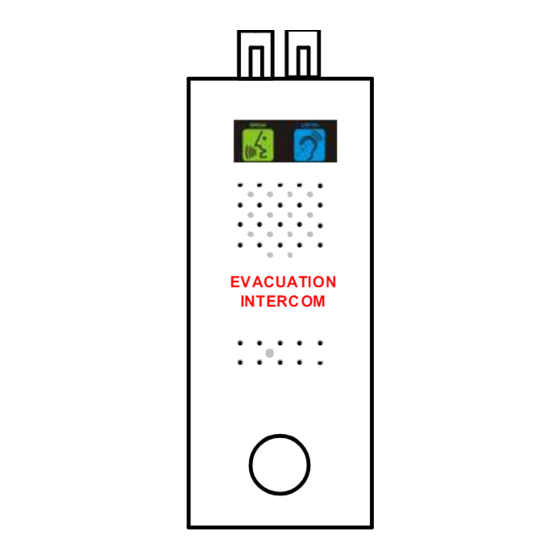
- Page 1 Evacuation Intercom System with Keypad & Display TYPE: SERIAL BUS...
- Page 2 IMPORTANT: READ PRIOR TO INSTALLATION Each Landing Speaker supplied should be installed on the designated landing as they are pre-assigned a unique address (Do not change the address as they are assigned from the factory. Contact Windcrest before changing address). The Master Switching Panel (with push buttons for each landing) should be ...
- Page 3 CAT5 Cable Lift Shaft CAT5 Cable Evacuation Intercom Power Supply Floors 43 to 34 CAT5 Cable This area represents Lift Motor Room EVACUAT ION INTE RCOM 12 Way Travelling Cable 0.75mm Cable Floor 34 Min. 6 way screened & twisted with min.
- Page 4 CAT5 Cable Lift Shaft CAT5 Cable Evacuation Intercom Power Supply Floors 43 to 34 CAT5 Cable This area represents Lift Motor Room EVACUAT ION INTE RCOM 12 Way Travelling Cable 0.75mm Cable Floor 34 Min. 6 way screened & twisted with min.
-
Page 5: Power Booster
Evacuation Intercom Power Supply Unit This area represents CAT5 Cable Lift Motor Room Lift Shaft CAT5 Cable Evacuation Intercom Power Supply Floors 43 to 34 CAT5 Cable M 0 B + - EVACUAT ION INTE RCOM 12 Way Travelling Cable 0.75mm Cable Floor 34... - Page 6 CAT5 Cable Lift Shaft CAT5 Cable Evacuation Intercom Power Supply Floors 43 to 34 CAT5 Cable This area represents Lift Motor Room EVACUAT ION INTE RCOM 12 Way Travelling Cable 0.75mm2 Cable Floor 34 Min. 6 way screened & twisted with min.
- Page 7 Note:- This is a generic system drawing and the installation may very depending upon the position of cables and master panel. CAT5 Cable Lift Shaft CAT5 Cable Evacuation Intercom Power Supply Top Landing CAT5 Cable This area represents Lift Motor Room EVACUAT ION INTE RCOM 12 Way Upto 10...
- Page 8 Evacuation Functions Lift Controller Spare Contacts:- Blue – Common / Green - Normally Open/ Yellow- Normally Closed Above contacts are rated at 40V Max @ 500mA. Operation:- Windcrest When The Evacuation & Fire Fighting Switches are switched OFF. EVAC/FF SYSTEM OFF When The Evacuation System is Turned ON EVACUATION SYSTEM ON Both the Pictograms will flash alternatively for 5 seconds and then remain Solid ON.
- Page 9 Evacuation Intercom Power Supply Unit M 0 B + - 12V Output Mains Detection Relay Output (“0” - Common, “M” - Normally Open) Mains Failure = Closed Mains Good = Open Low Battery Relay Output (“0” - Common, “B” - Normally Open) Low Battery = Closed Battery Good = Open NB: The buzzer is connected inside the PSU for Low Battery warning as standard.
- Page 10 Green (Autodialler ‘G’) Black (Not Used) Note:- If the Autodialler is Red (Autodialler ‘+’) already wired, please Yellow (Autodialler ‘Y’) refer to the Page 8. White Cable for Lift Car Alarm Push Pictogram/Loop/Amplifier in the Lift Serial Data Controller To Autodialler ‘+’ To Autodialler ‘A’...
- Page 11 Green (Autodialler ‘G’) Black (Not Used) Yellow (Autodialler ‘Y’) Red (Autodialler ‘+’) White Cable for Pictogram/Loop/ Disconnect the wire connected to Amplifier the Existing Autodialler Terminal “A” and connect to this terminal Serial Data Controller Disconnect the wire connected to the Existing Autodialler “+”...
- Page 12 Serial Evacuation-AD1000EN-xR Interface for the Car Speaker & Lift Car Alarm Push...
- Page 13 CAR/D CAR/S PIT/D PIT/S TOP/D TOP/S MR/S Serial Evacuation-AD1000EN-xR Interface for the Car Speaker & Lift Car Alarm Push...
- Page 14 RJ45 EVACUATION INTERCOM Cable 6 7 8 nth Floor Landing Speaker Box WRONG 1. Orange/White……….A (Data) 2. Orange……………….B (Data) 3. Green/White ………..+24V 4. Blue…………………..Audio EVACUATION INTERCOM 5. Blue/White…………...Audio nth Floor Landing 6. Green………………...Ground 7. Brown/White…………+24V 8. Brown………………...Ground Speaker Box RJ45 to Terminal 25-30V Data –...
- Page 15 Outstation Calling Level No. Lift Car --------------------------- 00 Basement ------------------------ Ground Floor -------------------- Landing 1 ------------------------ Landing 2 ------------------------ Landing 3 ------------------------ Landing 4 ------------------------ Landing 5 ------------------------ Landing 6 ------------------------ Landing 7 ------------------------ Landing 8 ------------------------ Landing 9 ------------------------ Landing 10 ------------------------ Landing 11 ------------------------ Landing 12 ------------------------...
Need help?
Do you have a question about the SERIAL BUS and is the answer not in the manual?
Questions and answers