Advertisement
Quick Links
Advertisement

Related Manuals for Wind Crest SERIAL BUS


Summary of Contents for Wind Crest SERIAL BUS
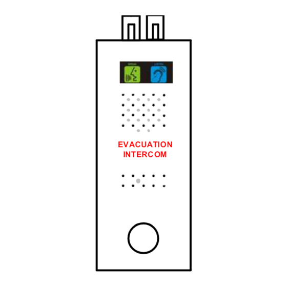
- Page 1 Evacuation Intercom System TYPE: SERIAL BUS...
- Page 2 IMPORTANT: READ PRIOR TO INSTALLATION Each Landing Speaker supplied should be installed on the designated landing as they are pre-assigned a unique address (Do not change the address as they are assigned from the factory. Contact Windcrest before changing address). The Master Switching Panel (with push buttons for each landing) should be ...
- Page 3 12 Way Cable to Power Booster if the no. of outstations are more than 10. Patch Cable Evacuation Intercom Power EVACUATION INTERC OM Supply This area represents Top most landing Motor Room Travelling Cable Evacuation Intercom Operation: EVACUATION INTERC OM When the system is operated, a speech link will open to allow communication between the Master Switching Panel and any of the...
- Page 4 After every 10 outstations a Motor Room (This area represents the Motor Room) 12 Way Cable to Power Booster will be required. Power Booster if Refer to Page 6. the no. of outstations are Evacuation Intercom more than 10. Power Supply 6 way CT5 Cable Windcrest...
- Page 5 Lift Shaft After every 10 outstations a (This area represents the Lift Shaft) Power Booster will be required. Refer to Page 6. 12 Way Cable to Power Booster if Evacuation the no. of Intercom outstations are Power Supply more than 10. CT5 Cable Top most landing 4 way...
- Page 6 After every 10 outstations a Power Booster will be required. Refer to Page 6. Top of the Shaft 230 VAC Evacuation Intercom Power Supply CAT 5 Cable Travelling Cable Top most landing Landing CAT5 Cable EVACUATION INTERCOM (Everything here is outside the lift, but near the lift door...
- Page 7 CAT5 Cable Lift Shaft CAT5 Cable Evacuation Intercom Power Supply This area represents Lift Motor Room or Top of the Lift Shaft CAT5 Cable 10 outstations To Lift Car EVACUATION INTERCOM Travelling Cable Min. 6 way screened & twisted with min. of 0.75mm conductor (Travelling Cable will be required if the system is...
- Page 8 CAT5 Cable Lift Shaft CAT5 Cable Evacuation Intercom Power Supply This area represents Lift Motor Room or Top of the Lift Shaft CAT5 Cable 10 outstations Evacuation Intercom Power Supply Unit EVACUATION INTERCOM 12 Way Cable Power M 0 B Booster CAT5 Cable 12 Way Cable...
- Page 9 CAT5 Cable Lift Shaft CAT5 Cable Evacuation Intercom Power Supply This area represents Lift Motor Room or Top of the Lift Shaft CAT5 Cable 10 outstations EVACUATION INTERCOM 12 Way Cable Power Booster CAT5 Cable 12 Way Cable 10 outstations EVACUATION INTERCOM POWER BOOSTER Power...
- Page 10 RJ45 EVACUATION INTERCOM Cable 6 7 8 nth Floor Landing Speaker Box WRONG 1. Orange/White……….A (Data) 2. Orange……………….B (Data) 3. Green/White ………..+24V 4. Blue…………………..Audio EVACUATION INTERCOM 5. Blue/White…………...Audio nth Floor Landing 6. Green………………...Ground 7. Brown/White…………+24V 8. Brown………………...Ground Speaker Box RJ45 to Terminal 25-30V Data –...
- Page 11 Evacuation Functions Interconnection Connect the main Evacuation Panel to the Control Box. Connect all the Landing Speakers to the bus. Lift Controller Contacts are provided on the Main Panel. Lift Controller Spare Contacts:- Blue or Orange - Common Green or White- Normally Open Yellow- Normally Closed Above contacts are rated at 40V Max @ 500mA.
- Page 12 All speakers have unique address. This address is set by the Dip Switch on the back of the each speaker box. Following are the arrangements for the Dip Switch for the different speaker box. Note: X – Do Not Care Car Speaker Master Panel :- This address will define the number of outstations (Excluding Lift Car (Default)).
- Page 13 Green (Autodialler ‘G’) Black (Not Used) Note:- If the Autodialler is Red (Autodialler ‘+’) already wired, please Yellow (Autodialler ‘Y’) refer to the Page 10. White Cable for Lift Car Alarm Push Pictogram/Loop/Amplifier in the Lift Serial Data Controller To Autodialler ‘+’ To Autodialler ‘A’...
- Page 14 Green (Autodialler ‘G’) Black (Not Used) Yellow (Autodialler ‘Y’) Red (Autodialler ‘+’) White Cable for Pictogram/Loop/ Disconnect the wire connected to Amplifier the Existing Autodialler Terminal “A” and connect to this terminal Serial Data Controller Disconnect the wire connected to the Existing Autodialler “+”...
- Page 15 Serial Evacuation-AD1000EN-xR Interface for the Car Speaker & Lift Car Alarm Push...
- Page 16 CAR/D CAR/S PIT/D PIT/S TOP/D TOP/S MR/S Serial Evacuation-AD1000EN-xR Interface for the Car Speaker & Lift Car Alarm Push...
- Page 17 Evacuation Intercom Power Supply Unit M 0 B + - 12V Output Mains Detection Relay Output (“0” - Common, “M” - Normally Open) Mains Failure = Closed Mains Good = Open Low Battery Relay Output (“0” - Common, “B” - Normally Open) Low Battery = Closed Battery Good = Open NB: The buzzer is connected inside the PSU for Low Battery warning as standard.
Need help?
Do you have a question about the SERIAL BUS and is the answer not in the manual?
Questions and answers