Advertisement
Quick Links
Seventh Circle Audio
⎯⎯⎯⎯⎯⎯⎯⎯⎯⎯⎯⎯⎯⎯⎯⎯⎯⎯⎯⎯⎯⎯⎯⎯⎯⎯⎯⎯⎯⎯⎯⎯⎯⎯⎯⎯⎯⎯⎯⎯⎯⎯⎯⎯⎯⎯⎯⎯⎯⎯⎯⎯⎯⎯⎯⎯⎯⎯⎯⎯⎯⎯⎯
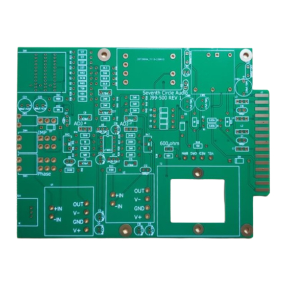
The J99-500 is a kit version of the Jensen Twin Servo circuit, the basis for some very well
known and highly regarded microphone preamps. The J99-500 provides exceptional
performance with high gain, extremely low noise and distortion, plus the benefits of transformer
coupling at both input and output.
Who Should Build This Kit?
The J99 is not difficult to build, but it is not intended for absolute beginners. If you've never built
an electronic project before, this is probably not the one to start with. To guarantee success,
make sure you have:
• The ability to make basic voltage and resistance measurements using a digital multi-
meter (DMM).
• At least a rudimentary understanding of voltage, current, and resistance.
• Some experience soldering on printed circuit boards.
• The patience to follow instructions precisely and work carefully.
Essential Tools
Fine tipped 20-30 watt soldering iron w/ cleaning sponge (Hakko 936 or similar)
Eutectic (63/37) rosin core or "no clean" solder (.025" diameter is usually best)
Good-quality DMM
Small needle nose pliers
Small diagonal cutters
Wire stripper
Phillips screwdriver (#1)
Precision straight blade screwdriver (for adjusting potentiometers)
Highly Recommended Tools
Lead bender (Mouser 5166-801)
T-Handle wrench and 4-40 tap (Hanson 12001 and 8012)
MOLEX crimp tool (Waldom W-HT1919 or equivalent)
Magnifying glass
Optional Tools
Panavise w/ circuit board head
1/4" nut driver
Oscilloscope
Signal generator
Page 1 of 16
J99-500 Microphone Preamp
Advertisement

Subscribe to Our Youtube Channel
Related Manuals for Seventh Circle Audio J99-500


Summary of Contents for Seventh Circle Audio J99-500
- Page 1 ⎯⎯⎯⎯⎯⎯⎯⎯⎯⎯⎯⎯⎯⎯⎯⎯⎯⎯⎯⎯⎯⎯⎯⎯⎯⎯⎯⎯⎯⎯⎯⎯⎯⎯⎯⎯⎯⎯⎯⎯⎯⎯⎯⎯⎯⎯⎯⎯⎯⎯⎯⎯⎯⎯⎯⎯⎯⎯⎯⎯⎯⎯⎯ J99-500 Microphone Preamp The J99-500 is a kit version of the Jensen Twin Servo circuit, the basis for some very well known and highly regarded microphone preamps. The J99-500 provides exceptional performance with high gain, extremely low noise and distortion, plus the benefits of transformer coupling at both input and output.
- Page 2 Work Area Find a clean, flat, stable, well-lit surface on which to work. An anti-static mat is recommended for this project. If you’re in a dry, static-prone environment, it’s highly recommended. The importance of good lighting can’t be overstated. Component markings are tiny, and you’ll be deciphering a lot of them.
- Page 3 Assembly Before you begin, carefully unpack the kit and examine the parts. Check the contents of each small bag against the BOM to make sure all the parts have been included. If you think something’s missing, please e-mail the details to sales@seventhcircleaudio.com and we’ll ship replacement parts ASAP.
- Page 4 Add the protection diodes D1 – D11. Diodes are polarized and must be installed the right way around! The colored band on the diode matches the white band on the silkscreen. Insert the 1/4-watt resistors. Check the Bill of Materials (BOM) for help in reading the resistor color bands.
- Page 5 Add small, yellow ceramic capacitors These capacitors are not polarized and can be installed in either direction, but pay close attention to the capacitor markings! blue EMI filters L1 through L6. These parts are not polarized and can be installed in either direction.
- Page 6 Add the 0.1" 2-pin and 3-pin headers now. J5 connects a 604-ohm load resistor across the output. Unless you’ll be connecting the J99 to a piece of older gear with 600 ohm input impedance, dont connect a jumper at J6 and J7 – These headers allow the servos to be switched out of the circuit for adjustment as described in the testing section below.
- Page 7 10. Add power supply components: L101, C104, C105, C2, and U4. 11. Add trim pots R43 and R47. R43 and R47 are used in the bias current compensation adjustment described later. Page 7 of 16...
- Page 8 12. Add Q7, U6 and U7. Be sure to install semiconductors correctly! These parts are not the same and they are not interchangeable. Read the markings carefully and orient Don’t mix up the positive and the packages according to the silkscreen outlines. negative regulators and the transistor! 13.
- Page 9 14. The first components to place are the Mill-Max receptacles. Press them into the holes using the point of a Philips screwdriver or similar tool. Be sure to support the board from behind while applying pressure. Push the sockets in until they're flush with the board, and solder them from the back.
- Page 10 16. Attach gain trim control R24. Make sure the control is seated flat to the board before soldering the leads. You may want to add a small dab of silicone adhesive to the bottom of the control to hold it more securely, but it isn’t necessary. 17.
- Page 11 18. Secure the pin with the adhesive foil supplied. 19. Make sure the switch is fully seated and solder it to the board. Try to make your solder joints as neat as possible, and don’t use too much solder. 20. Add the input transformer now. Page 11 of 16...
- Page 12 21. Add U3 now. Orient the IC according to the silkscreen. 22. Attach the output transformer to the board using two 1" 4-40 machine screws and nuts. Use the supplied spacers between the transformer and the circuit board. Trim the leads to length, and strip about 1/4"...
- Page 13 24. That’s it for PCB assembly! Before going on to initial power-up, carefully check your work. Make sure you haven't created any solder bridges between pads, or between a pad and the ground plane. Initial Power-Up and Testing. 25. Again, carefully check your work. Make sure you've got the right resistors in the right locations.
- Page 14 Input Bias Current Adjustment The J99 employs a servo around each op-amp to automatically minimize DC offset. Excessive offset can reduce available headroom and cause excessive heating of U2 so it’s a good idea to minimize it, but it has virtually no effect on the audio performance of the amplifier.
- Page 15 Installation into 500 series case 1. Make sure all 4 standoffs/spacers are installed. Short M-F spacer on the bottom, long on top of the PCB. 2. With nuts and washers from rotary switch and gain trim removed, fit the switches through the holes on the bottom tray.
- Page 16 3. Use 4 small flat head screws to secure PCB to bottom tray. 4. Install cover using 4 small flathead screws. 5. Attach faceplate using the nuts, but NOT the washers! Add knobs to the front. 6. Congratulations! You have completed your build! Page 16 of 16...
Need help?
Do you have a question about the J99-500 and is the answer not in the manual?
Questions and answers