Advertisement
Quick Links
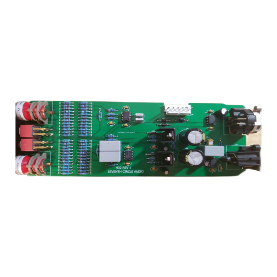
Seventh Circle Audio
Who Should Build This Kit?
The H32 is not difficult to build, but it is not intended for absolute beginners. If you've never
built an electronic project before, this is probably not the one to start with. To guarantee
success, make sure you have:
•
The ability to make basic voltage and resistance measurements using a digital
multimeter (DMM).
•
At least a rudimentary understanding of voltage, current, and resistance.
•
Some experience soldering on printed circuit boards.
•
The patience to follow instructions precisely and work carefully.
Essential Tools
Fine tipped, 20-30 watt soldering iron w/ cleaning sponge (Hakko 936 or similar)
Eutectic (63/37) rosin core or "no clean" solder (.025" diameter or smaller is best)
Good-quality DMM
Small needle nose pliers
Small diagonal cutters
Phillips screwdriver (#1)
Precision straight blade screwdriver (for adjusting potentiometers)
Highly Recommended Tools
Lead bender (Mouser 5166-801)
T-Handle wrench and 4-40 tap (Hanson 12001 and 8012)
MOLEX crimp tool (Waldom W-HT1919 or equivalent)
Magnifying glass
Optional Tools
Panavise w/ circuit board head
Oscilloscope
Signal generator
Work Area
Find a clean, flat, stable, well-lit surface on which to work. An anti-static mat is recommended
for this project. If you're in a dry, static-prone environment, it's essential. The importance of
good lighting can't be overstated. Component markings are tiny, and you'll be deciphering a lot
of them.
H32 Microphone Preamp Rev 1.2
Pag e 1 o f 11
Advertisement

Subscribe to Our Youtube Channel
Related Manuals for Seventh Circle Audio H32


Summary of Contents for Seventh Circle Audio H32
- Page 1 H32 Microphone Preamp Rev 1.2 Who Should Build This Kit? The H32 is not difficult to build, but it is not intended for absolute beginners. If you’ve never built an electronic project before, this is probably not the one to start with. To guarantee success, make sure you have: •...
- Page 2 C84 Assembly Instructions Soldering Technique Make sure your irons tip is tinned properly and keep it clean! The trick to making perfect solder joints is to heat the joint quickly and thoroughly before applying the solder, and a properly tinned and clean tip is essential for this. Apply enough solder to form a "fillet" between the lead and the pad, a little mound of solder that smoothly transitions from the plane of the board up to the lead, but don’t use too much.
- Page 3 C84 Assembly Instructions Assembly Before you begin, carefully unpack the kit and examine the parts. Check the contents of each small bag against the BOM to make sure all the parts have been included. If you think something’s missing, please e-mail the details to sales@seventhcircleaudio.com we’ll ship replacement parts ASAP.
- Page 4 C84 Assembly Instructions Insert the 1/4-watt resistors. Check the Bill of Materials (BOM) for help in reading the resistor color bands. It's also a good idea to actually measure each resistor with your DMM as you place it on the board, just in case you've decoded it incorrectly. Don't rely on the photos for component placement.
- Page 5 C84 Assembly Instructions Add the small yellow ceramic capacitors. These capacitors are not polarized and can be installed in either direction, but pay close attention to the capacitor markings! These parts all look alike, but they are not interchangeable. Putting one in the wrong spot will not prevent the preamp from passing signal, but it can seriously impair its performance.
- Page 6 C84 Assembly Instructions Install the 1uF film caps at C7, C8 and C15. These parts are not polarized and can be installed in either direction. Add the electrolytic capacitors now. C13 and C17 are not polarized, but the rest are must be installed the right way around! Be absolutely sure to observe the correct polarity when installing these parts.
- Page 7 C84 Assembly Instructions 10. Carefully mount the toggle switches SW101 and SW201. Be sure they're seated flat on the board before soldering all the pins. You may find it easier to solder the first pin with the board component side up. 11.
- Page 8 C84 Assembly Instructions 12. Using the hardware supplied, attach heat sinks to U301 and U302 and solder them in place. Make sure to install the regulators correctly! These parts are not the same and are not interchangeable. 13. Install rotary switches. Make sure the switches are fully seated and solder them to the board.
- Page 9 C84 Assembly Instructions 14. Add CONN1 and CONN2 to the board. Make sure they’re fully seated before soldering. 15. Install the bulk filter capacitors C302 and C305. Push them in firmly until they are fully seated against the board. Again, electrolytic capacitors are polarized and must be installed the right way around! Be absolutely sure to observe the correct polarity when...
- Page 10 C84 Assembly Instructions 16. Before going on to initial power-up, carefully check your work. Make sure you haven't created any solder bridges between pads, or between a pad and the ground plane. Page 10 of 11...
- Page 11 100 ohms, don't apply power. Carefully check your work until you find that short. 19. Connect the PS03 to J301 on the H32 using a WH01 wire harness or similar. Verify that there are no crossed wires or loose crimps in the harness. Be sure the locking ramps engage.
Need help?
Do you have a question about the H32 and is the answer not in the manual?
Questions and answers