VORON GALILEO 2 EXTRUDER Manual
Hide thumbs
Also See for GALILEO 2 EXTRUDER:
- Assembly manual (120 pages) ,
- Assembly instructions manual (12 pages)

Related Manuals for VORON GALILEO 2 EXTRUDER


Summary of Contents for VORON GALILEO 2 EXTRUDER
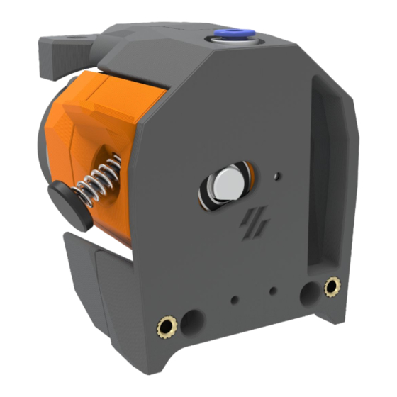
- Page 1 VORON GALILEO 2 EXTRUDER Planetary power for your gardening-tool-built space shuttle. VERSION 25SEPT2023...
-
Page 2: Table Of Contents
TABLE OF CONTENTS VORONDESIGN.COM Introduction Galileo 2 Introduction Configuration Requirements Hardware References Heatset Prep Front Body Gearbox Assembly G2 Module Rear Body... -
Page 3: Introduction
PART PRINTING GUIDELINES Galileo 2 follows the Voron Team standards. The Voron Team has provided the following print guidelines for you to follow in order to have the best chance at success with your parts. There are often questions about substituting materials or changing printing standards, but we recommend you follow these. - Page 4 FILE NAMING By this time you should have already downloaded the STL files from the Galileo 2 GitHub repository. You might have noticed that we have used the Voron standard naming convention for the files. This is how to use them.
- Page 5 If you need assembly assistance, we’re here to help. Head on over to the Voron Discord group and post your questions. This is our primary medium to help Voron Users and we have a great community that can help you out if you get stuck.
- Page 6 INTRODUCTION VORONDESIGN.COM REPORTING AN ISSUE Should you find an issue in the documentation or have a suggestion for an improvement please consider opening an issue on GitHub (https://github.com/JaredC01/Galileo2/issues). When raising an issue please include the relevant page numbers and a short description; annotated screenshots are also very welcome. We periodically update the manual based on the feedback we get.
- Page 7 This document covers Galileo 2, or G2, which has an incredible 9:1 gear ratio in a custom-designed planetary gearbox. This manual covers the Galileo 2 Extruder, or G2E, specifically. There are also other G2-based projects, such a G2Z drives and a standalone extruder design, which will be covered in separate manuals.
- Page 8 CONFIGURATION REQUIREMENTS VORONDESIGN.COM G2E CONFIGURATION You must update both the gear_ratio and rotation_distance in your Klipper configuration and do a standard extruder calibration after installing the Galileo 2 Extruder. Additionally, your run_current will need to be updated. [extruder] rotation_distance: 47.088 gear_ratio:...
- Page 9 EXPLODED DIAGRAM VORONDESIGN.COM FOR REFERENCE ONLY If yours explodes and ends up looking like this, you may have a problem. Please ask for help.
-
Page 10: Hardware References
The most common As the plastic cools, it solidifies around fastener used on the Voron. the knurls and ridges on the insert for excellent resistance to both torque and ISO 4762 pull-out. - Page 11 VORONDESIGN.COM PLANETARY GEAR NEMA 14 PANCAKE STEPPER 31-Tooth MJF Gear 9T, 20mm ECAS fitting GALILEO 2 EXTRUDER GEAR You won’t need the black rubber RNC-Coated 16mm Drive Gear part on the bottom RING GEAR HOUSING PLANETARY CARRIER SHAFT 72-Tooth MJF Housing...
- Page 12 HARDWARE - REFERENCES VORONDESIGN.COM 16mm x 5mm OD...
-
Page 14: Heatset Prep
This design relies on heat set inserts. Make sure you have the proper inserts (check the hardware reference for a close-up picture, and the BOM for dimensions). If you’ve never worked with heat set inserts before, we recommend you watch the linked guide. https://voron.link/m5ybt4d... - Page 15 HEATSET PREP - FRONT BODY VORONDESIGN.COM THAT LITTLE GUY? Don’t forget the heatset in the idler bearing cover, which is also part of the front body assembly. Heat Set Insert...
- Page 16 HEATSET PREP - G2 MODULE VORONDESIGN.COM Heat Set Insert...
- Page 17 HEATSET PREP - REAR BODY VORONDESIGN.COM YES..MORE HEAT SETS Just when your your iron timed out and shut off, we found another. Heat Set Insert...
- Page 18 HEATSET PREP - REAR BODY VORONDESIGN.COM GOT CHAINS? Heat Set Insert Make sure to print the version that matches your chains— some take two screws (shown), some take three.
- Page 20 FRONT BODY - ASSEMBLY VORONDESIGN.COM 5x16 Pin PUT A PIN IN IT Install the first of the two pins included with the kit into the hexagonal hole in the front body until it’s fully seated into the housing. This pin will hold the idler bearing opposite the drive gear in G2 extruder design.
-
Page 21: Front Body
FRONT BODY - ASSEMBLY VORONDESIGN.COM MR115 Bearing IDLING ON BY Seat the idler bearing onto the pin, taking care to fully seat the bearing until it is flat against the printed part. TAKE COVER! Install the idler bearing cover onto the back of the 5mm pin, NOTE: The pin and bearing have very tight tolerances;... - Page 22 FRONT BODY - ASSEMBLY VORONDESIGN.COM BEARING SECURITY Whether or not you are using a toolhead board with G2, you will need to put a screw in the front mount hole to secure the idler bearing cover properly. The M3x8 SHCS bolt included will fit most toolhead boards as well.
- Page 23 FRONT BODY - ASSEMBLY VORONDESIGN.COM PIVOT BEARING Insert the bearing into the front body. This should install with a small amount of force and should sit flush with the raised lip around the bearing. If you ever need to remove this bearing, use the ejecto-seato holes in the front! MR115 Bearing...
- Page 24 FRONT BODY - ASSEMBLY VORONDESIGN.COM ECAS PREP ECAS Collet The rubber donut on the bottom highlighted here is not used in this build. Pry the rubber donut off and set it aside where pets won’t find a way to use it to increase your vet bill.
- Page 26 G2 MODULE - GEARBOX ASSEMBLY VORONDESIGN.COM HOW DO YOU THROW A PARTY ABOUT SPACE?…..YOU PLANET! Planetary gearbox assembly can be a tedious process, but following these steps closely will ensure a smoothly running gearbox! INTERGALACTIC, PLANETARY! Start by inserting the bearings for each of the three (3) planetary gears.
- Page 27 G2 MODULE - GEARBOX ASSEMBLY VORONDESIGN.COM CARRIER ON MY WAYWARD SUN! Ensure the aluminum planetary carrier is clean Carrier and free from dust or other particles. Install the three (3) planetary gears from the previous step onto each of the carrier pins. The bearings should slide easily onto the carrier.
-
Page 28: G2 Module
G2 MODULE - GEARBOX ASSEMBLY VORONDESIGN.COM YOU KNOW WHAT REALLY GRINDS MY GEARS? The G2 gearbox is made from MJF Nylon, and as such, is subject to printed part tolerances just like any other printed part. Unfortunately this means that some gearboxes will be tighter than others out of the box. The best way to ensure a smooth-running gearbox is to manually run-in the gears using a drill! Start by wrapping the carrier shaft with a strip of paper to protect it, then loosely chuck it into your drill. - Page 30 G2 MODULE - ASSEMBLY VORONDESIGN.COM BEARING IT DOWN Insert the bearing into the rear half of the G2 Module. This bearing should install with a small amount of force and should sit flush with the lip of the printed part. MR148 Bearing...
- Page 31 G2 MODULE - ASSEMBLY VORONDESIGN.COM BEARING RETAINER SCREWS These capture the outer edge of the bearing and will retain it in the printed part. They should be just above flush when fully tightened. DO NOT OVERTIGHTEN, they are threaded into plastic! M3x6 FHCS...
- Page 32 G2 MODULE - ASSEMBLY VORONDESIGN.COM THE PLANETS ARE ALIGNING Install the completed planetary assembly into the rear bearing assembly of the G2 Module. When fully seated, there should be no gap between the MJF ring gear housing and the printed ABS parts. Shim...
- Page 33 G2 MODULE - ASSEMBLY VORONDESIGN.COM ONE SMALL STEP FOR THE MOTOR, ONE GIANT REVOLUTION FOR THE GEARBOX. Aligning the stepper is one of the more challenging parts of G2, as it can be installed a tooth off, which will cause binding during operation.
- Page 34 G2 MODULE - ASSEMBLY VORONDESIGN.COM EVERY STEP COUNTS M3x30 SHCS With the rear-half of the G2 Module assembled, it’s time to put on the front! Slide the front half of the G2 module onto the carrier shaft and fasten everything together with 2x M3x30 SHCS. Snug the screws down for now, but they may need adjusting in a later step when installing the pivot pin!
- Page 35 G2 MODULE - ASSEMBLY VORONDESIGN.COM PLANETARY EXTRUSION? IT’S OUT OF THIS WORLD! Ensure the flat face of the carrier shaft is facing out towards the opening in the G2 Module so that the drive gear grub screw is accessible. Install the custom 16mm drive gear onto the carrier shaft, ensuring the filament path is facing outward.
- Page 36 G2 MODULE - ASSEMBLY VORONDESIGN.COM SHAFT SUPPORT The shaft support bearing needs to be pressed into the front bearing holder until it is flush with the outside face of the printed part. Slide the completed front bearing holder over the carrier shaft, align the screw holes, then attach to the rest of the G2 Module assembly using 2x M3x8 SHCS.
- Page 37 G2 MODULE - ASSEMBLY VORONDESIGN.COM PIVOT! PIVOT! PIVOT! Insert the pivot pin into the G2 module and roughly center it. The pin will self-center when installing the G2 module into the rest of the extruder parts. If you have trouble inserting the pin, loosen each of the stepper screws one full turn and try again.
- Page 38 G2 MODULE - DOCKING VORONDESIGN.COM SEQUENCE PREPARE FOR DOCKING! Align the G2 module’s pivot pin with the center of the pivot bearing in the front body and install the G2 module flush to the bearing.
- Page 40 REAR BODY - ASSEMBLY VORONDESIGN.COM LOST IN SPACE? BETTER FIND YOUR BEARINGS! Install the FINAL bearing, making sure to prevent the bearing from tilting sideways while inserting. This bearing can be tricky to install due to the position of the bearing in the printed part. MR115 Bearing...
-
Page 41: Rear Body
REAR BODY - ASSEMBLY VORONDESIGN.COM DOCKING SEQUENCE INITIATED Install the rear body over the pin in the G2 module, pressing firmly. The rear body should be completely flush with the front body when the pin in the G2 Module is properly aligned / centered. - Page 42 REAR BODY - ASSEMBLY VORONDESIGN.COM M3x20 SHCS IN SPACE EVERY DOOR IS AN ESCAPE HATCH Tighten the screw down just until snug. The door should hold itself open, but move freely.
- Page 43 REAR BODY - ASSEMBLY VORONDESIGN.COM CHAINED UP! Here’s where you find out just how straight you installed the heatset earlier.. M3x50 SHCS...
- Page 44 REAR BODY - ASSEMBLY VORONDESIGN.COM SHUT THAT DOOR… YOU’LL LET THE VACUUM IN! The wire cover gets fastened with a single M3x6 FHCS. Install it for now, but know it will need to be removed for wiring when installing the extruder to the toolhead.
- Page 45 FRONT BODY - THUMBSCREW VORONDESIGN.COM LATCHES? WHERE WE’RE GOING, WE DON’T NEED LATCHES G2E does away with the latch and instead uses the M3 Thumbscrew and a finger hold to load/unload filament. With the G2 Module fully installed, and G2E nearly complete, install the tension thumbscrew through the G2 Module and into the heatset in the Front Body.
- Page 46 VORONDESIGN.COM COOPER WHAT ARE YOU DOING? DOCKING! At this point it is time to install the Galileo 2 Extruder onto the X carriage. The G2 slots into the X carriage just like CW2. The only difference in mounting is the hardware used.
- Page 47 INSTALL - HOTEND VORONDESIGN.COM INTO THE WORMHOLE There are 2 methods you can use to setup the PTFE tube. If you are swapping from CW2 then you will already have a PTFE tube you can just add to that with a new 18.9mm piece or you can use the PTFE cutting jig in the G2 repo and cut a new piece.
- Page 48 INSTALL - STEALTHBURNER VORONDESIGN.COM THE LAST OF US! CW2 and G2 also differ slightly in the top 2 screws to secure the Stealthburner. G2 has less space for those screws so there were shortened M3x20 SHCS...
- Page 50 VORON VORONDESIGN.COM...
Need help?
Do you have a question about the GALILEO 2 EXTRUDER and is the answer not in the manual?
Questions and answers