
Related Manuals for Omega Bio-Tek MagBinder Fit24

Summary of Contents for Omega Bio-Tek MagBinder Fit24
- Page 1 MagBinder® Fit Nucleic Acid Purification System Operation Manual Manual Date: December 2023 Manual Revision: v1.0 For Research use only...
-
Page 2: Foreword
Opening Inspection Please check the instrument when you first open the package. If you find anything missing or incorrect, please contact us at info@omegabiotek.com. Omega Bio-tek 400 Pinnacle Way, Suite 450 Norcross, GA 30071 Phone: +1-770-931-8400 Email: info@omegabiotek.com... -
Page 3: Equipment Contents
Equipment Contents Item Quantity Main Unit Power Cord Tray Tray Supports Mouse Allen Wrench, 2.5 mm Allen Wrench, 3.0 mm Qualification Kit MagBinder® Fit Qualification Kit is included with purchased equipment however the kit is shipped separately. QMF27.0352.B1-001-24 Revision 1.0... -
Page 4: Safety Warnings And Guidelines
Safety Warnings and Guidelines 1. General safety Please read this user manual carefully in its entirety before operation. Prior to operating the instrument, thoroughly review this user manual. Neglecting to read, comprehend, and adhere to the manual’s instructions could lead to instrument damage, potential harm to operator, or suboptimal instrument performance. - Page 5 Safety Warnings and Guidelines Ensure that the power cord remains unobstructed and is positioned away from high traffic areas while in operation. When disconnecting the plug from the outlet, be certain to grasp the plug securely and refrain from exclusively tugging on the power cord.
- Page 6 Safety Warnings and Guidelines This instrument contains permanent magnets. Operators wearing a pacemaker or metallic prostheses should not use this instrument. Close contact with a magnetic field may damage or affect the pacemaker or prostheses. Avoid placing the MagBinder® Fit in proximity to magnetic tapes, computer media, or other magnetic storage devices as the magnetic field generated by the instrument rods can...
-
Page 7: Preventative Maintenance
Safety Warnings and Guidelines 3. Preventative maintenance To ensure consistent daily performance, maintain the instrument in an environment free from dust and liquid spills. Avoid the use of abrasive cleaning agents, as they are prone to cause damage to the instrument. When necessary, clean the external surfaces or covers of the instrument using a cloth dampened with water or a mild detergent. - Page 8 The user will send products under warranty to the maintenance department designated by Omega Bio-tek. The user will pay for freight delivery of the instrument to the company, and the company will pay for the return.
-
Page 9: Table Of Contents
Table of Contents Foreword...................i Equipment Contents..............ii Safety Warnings and Guidelines..........iii 1. General safety..............iii 2. Safety tips.................iii 3. Preventative Maintenance..........vi 4. Transportation and storage guidelines....vii 5. Warranty and service...........vii Chapter 1 Introduction..............1 1.1 Intended Use..............1 1.2 Manufacturer’s Warranty..........1 1.3 Features................2 Chapter 2 Specifications.............3 2.1 Normal Operating Guidelines........3 2.2 Basic Parameters &... - Page 10 Table of Contents Chapter 5 Operation..............12 5.1 Start-up Interface............12 5.2 Run Program..............13 5.3 Program Management..........16 5.4 System Settings.............23 5.5 UV Decontamination..........26 5.6 Help................27 5.7 Exit Program/Power Off Instrument.......27 Chapter 6 Troubleshooting.............28 Chapter 7 Abbreviations & Symbols........30 7.1 Abbreviations............30 7.2 Symbols.............31 Contact Information..............33 Ordering Information..............34 Revision History................35...
-
Page 11: Chapter 1 Introduction
The MagBinder® Fit comes with preloaded protocols designed to work with Omega Bio-tek kits. Please reference specific kits for instructions on how to run the preloaded protocols. Should there be any questions about instrument protocols, reach out to Omega Bio-tek at info@omegabiotek.com. -
Page 12: Features
Chapter 1 Introduction 1.3 Features • Easy-to-use touch screen interface • 3 shortcut keys and/or mouse operation • Heat function available • UV light for instrument decontamination • Quiet operation with minimal vibration • Minimal interaction once samples running on instrument QMF27.0352.B1-001-24 Revision 1.0... -
Page 13: Chapter 2 Specifications
Chapter 2 Specifications 2.1 Normal operating guidelines Environmental temperature: 10°C – 35°C Relative humidity: ≤ 70% Input: AC 100 – 240 V, 50 Hz/60 Hz 2.2 Basic Parameters & Performance Table 1 Basic Parameters & Performance Parameter Model: MagBinder® Fit Principle Magnetic bead-based processing Throughput... -
Page 14: Overall Dimensions
Chapter 2 Specifications 2.3 Overall Dimensions Dimension (WxDxH) MagBinder® Fit : 400 mm x 530 mm x 480 mm QMF27.0352.B1-001-24 Revision 1.0... -
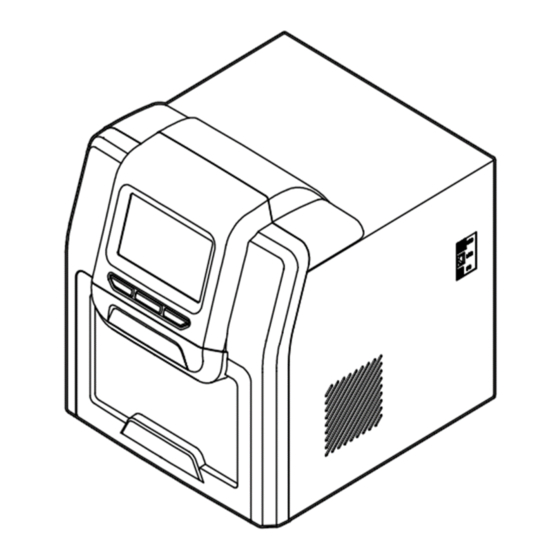
Page 15: Chapter 3 Product Schematic
Chapter 3 Product Schematic This section covers the instrument schematic and location of critical instrument features only. 3.1 Structure 3.1.1 Front 3.1.2 Back Power Switch Fuse Socket QMF27.0352.B1-001-24 Revision 1.0... -
Page 16: Operation Panel
Chapter 3 Product Schematic 3.1.3 MagBinder® Fit inside view 3.2 Operation panel Display screen: Touch screen operated or connect mouse to front USB port TAB: Select for the shortcut protocol RUN: Select to start the shortcut protocol STOP: Abort operations QMF27.0352.B1-001-24 Revision 1.0... -
Page 17: Chapter 4 Installation
Chapter 4 Installation 4.1 Before unpacking the instrument The MagBinder® Fit must be installed on a stable, level surface that can accommodate the weight (34 kg) and overall dimensions (400 mm x 530 mm x 480 mm) of the instrument. Ensure that the dedicated work area is clean, uncluttered and free of any obstructions that may interfere with the operation of the instrument. -
Page 18: Unpacking The Instrument
Chapter 4 Installation 4.2 Unpacking the instrument Carefully remove the instrument from its packaging and place it on a stable, level surface. The MagBinder® Fit weighs approximately 34 kg, and it is recommended that two persons lift the instrument together. Ensure that all components are present (refer to “Equipment Contents”... -
Page 19: Placing Tray Supports
Chapter 4 Installation 4.3 Placing tray supports Slide out the deck and place the tray supports as seen in Figure 3. Place the numbered support on the left side and the numbered on the right side of the deck. 4.4 Connecting power Connect one end of power cord to the instrument socket and the other to the power outlet (AC100~240 V). -
Page 20: Preparing The Reagents
Chapter 4 Installation 4.6 Preparing the reagents Place the reagent cartridges and elution tubes in the tray to the corresponding positions (Figure 4). Ensure the elution tubes are positioned open with caps oriented to the right of the tube and pressed down as shown in Figure 4. -
Page 21: Inserting/Removing Tip Combs
Chapter 4 Installation 4.7 Inserting/Removing tip combs Insert the tip comb by pushing it completely in on the mounting grooves located on the top of the magnetic arm. Push the tip comb completely to the back so that it is secured. (see red arrows, Figure 6). Remove the tip combs by pulling it out of the mounting groove. -
Page 22: Chapter 5 Operation
Chapter 5 Operation 5.1 Start-up Interface Before starting, make sure the door is closed. Turn on the instrument to display the booting interface. Once the instrument is ready, the display will change to the Shortcut screen shown below. QMF27.0352.B1-001-24 Revision 1.0... -
Page 23: Run Program
Chapter 5 Operation 5.2 Run Program 5.2.1 Shortcut In shortcut screen (pictured on previous page), select the desired program and press “Run” on the right side. This will lead to the program run interface. The program can also be selected by pressing the “Tab” button on the panel, then pressing “Run”... - Page 24 Chapter 5 Operation 5.2.2 Program pause or stop To stop a program select “Stop” during the run. Select “Cancel” for the program to continue running. Select “Confirm” and the program will be stopped and the user will be returned to the home screen. To restart the same program after stopping, select “Rerun”...
- Page 25 Chapter 5 Operation 5.2.3 List mode Users can see all the programs using the scroll bar on the right. Select the desired program from the list. Press “Run” to go to main screen and start the program. Select “View” to see the program steps and parameters. In this screen, select “Option”...
-
Page 26: Program Management
Chapter 5 Operation 5.2.4 Lamp At the bottom right corner of the screen, the icon “ “ indicates that the lamp is on. The icon “ “ indicates that the lamp is off. Select this icon to turn the instrument lamp on or off. 5.3 Program Management Select “Manage Prog. - Page 27 Chapter 5 Operation 5.3.2 Create new protocol Select “New - 5 mL” or “New - 10 mL” on the right side of the Manage Prog. screen to create a new protocol based on the reagent cartridge size. Create a name for the new protocol and press “Enter”. Select “Insert”...
- Page 28 Chapter 5 Operation Select “ “ to return to the parameters on the previous screen. Each parameter and its function is shown in the table below. Note that some parameters are disabled depending on the conditions of the step. Step Parameters and Function Parameter Description Function...
- Page 29 Chapter 5 Operation How long to wait Amount of time to wait Wait Time Input values between 0.0 after particle before starting next (min) and 99.0. collection step Total volume is used to determine Mix Pos, 10-mL strip: Max volume Mix Amp, and Mag Pos of first well, 10000 µL.
- Page 30 Chapter 5 Operation Option Parameters and Function Parameter Description Function Notes This option is Select a automatically disabled Enable or disable temperature when other wells besides Heat Block specified heat blocks module to turn it the first or last position during operation On/Off of selected cartridge...
- Page 31 Chapter 5 Operation Magnetization Magnetic rods move This option is dependent begins when to set position and on the Mag Pos parameter magnetic rods in holds during collection of step. pos. process Magnetic rods move This option is dependent Magnet Reciprocate up/down during on the Mag Pos parameter...
- Page 32 Chapter 5 Operation 5.3.3 Edit existing protocol In the Manage Prog. home screen, highlight the protocol of choice and select “Edit” on the right side of panel. On the next screen, highlight the step to edit. This will lead to the same screen as mentioned in 5.3.2 Create new protocol.
-
Page 33: System Settings
After selecting “Instrument” the user will be prompted to enter the administrator password. Access to “Instrument” settings is restricted by the vendor and will be used in cases if the instrument has failed a run or needs to be repaired. Contact Omega Bio-tek at info@ omegabiotek.com for more information. - Page 34 Chapter 5 Operation 5.4.2 Date & Time Select “Date & Time” to set instrument date and time. Setting can be adjusted by using the “+” or “–” on the touch screen or directly changing the numbers. 5.4.3 Language Select “Language” to set instrument language. QMF27.0352.B1-001-24 Revision 1.0...
- Page 35 Chapter 5 Operation 5.4.4 Exhaust Select “Air Ejector Fan” to adjust the fan setting. 5.4.5 Import & Export Select “Im. & Export” to transfer data to and from the instrument. The flash drive provided with the instrument contains an “Items” folder designated for transfering data.
-
Page 36: Uv Decontamination
Chapter 5 Operation 5.4.6 Software Update Please reach out to Omega Bio-tek at info@omegabiotek.com updates. 5.5 UV Decontamination Select “UV Sterilizer” at the top to set the sterilization time for the instrument. Setting can be adjusted by using the “+” or “–” on the touch screen or directly changing the numbers. -
Page 37: Help
Chapter 5 Operation During decontamination, if the door is opened, the UV light will automatically turn off. To resume decontamination, close the door. Important: UV treatment should not replace the cleaning process. Relying solely on the UV treatment may not ensure thorough decontamination. -
Page 38: Chapter 6 Troubleshooting
Switch failure Omega Bio-tek. properly when instrument is on Replace fuse (5X20 250V Fuse failure 8A). Other issues Contact Omega Bio-tek. Replace the light. Contact No UV light UV light failure Omega Bio-tek. Replace the light. Contact No light Light failure Omega Bio-tek. - Page 39 Chapter 6 Troubleshooting Problem Type Problem Name Error Message T1, T2, T3, T4 E011, E021, E031, E041 overheat T1, T2, T3, T4 E018, E028, E038, E048 drive circuit fault T1, T2, T3, T4 Temperature E015, E025, E035, E045 open circuit (Code: 0) T1, T2, T3, T4 E016, E026, E036, E046...
-
Page 40: Chapter 7 Abbreviations & Symbols
Chapter 7 Abbreviations & Symbols 7.1 Abbreviations Abbreviation Definition Ampere Alternating current Voltage Hertz Watt Universal serial bus Wi-Fi WLAN Kilogram Millimeter µL Microliter Hectopascal °C Degree centigrade Coefficient of variation Toggle selection Start operation STOP Stop operation QMF27.0352.B1-001-24 Revision 1.0... -
Page 41: Symbols
Chapter 7 Abbreviations & Symbols 7.2 Symbols Symbol Description Caution Hot surface Biological hazard Magnetic field Ultraviolet radiation Electrical input Manufacturer Date of manufacturer Consult instructions for use or consult electronic instructions for use Catalogue number Serial number Regulatory Mark Unique device identifier QMF27.0352.B1-001-24 Revision 1.0... - Page 42 Chapter 7 Abbreviations & Symbols RoHS compliance WEEE symbol. The product should be sent to separate collection facilities for recovery and recycling Website Telephone Email LinkedIn Twitter Facebook QMF27.0352.B1-001-24 Revision 1.0...
-
Page 43: Contact Information
Contact Information To reorder supplies, report a device failure or complaint, please contact: Manufacturer Omega Bio-tek, Inc. 400 Pinnacle Way Suite #450 Norcross, GA 30071, USA Website: www.omegabiotek.com Email: info@omegabiotek.com QMF27.0352.B1-001-24 Revision 1.0... -
Page 44: Ordering Information
Ordering Information Consumables and Accessories The following consumables and accessories are to be used with the MagBinder® Fit instrument and are available for purchase separately: Component Part No. MB Fit24™ Reagent cartridge, 5 mL (200 pack) PB07-5-200 MB Fit24™ Reagent cartridge, 10 mL (200 pack) PB05-10-50 Elution Tubes, 2 mL (200 pack) PB01-2-50... -
Page 45: Revision History
Revision History Revision Description v1.0, December 2023 Initial release QMF27.0352.B1-001-24 Revision 1.0...
Need help?
Do you have a question about the MagBinder Fit24 and is the answer not in the manual?
Questions and answers