Table of Contents
Advertisement
Quick Links
Advertisement
Table of Contents
Troubleshooting

Subscribe to Our Youtube Channel
Related Manuals for HILLENBRAND INDUSTRY Hill-Rom AvantGuard


Summary of Contents for HILLENBRAND INDUSTRY Hill-Rom AvantGuard
- Page 1 Service Manual AvantGuard™ Electric Bed QD1787...
- Page 3 AvantGuard™ Electric Bed Service Manual Revisions Revision Number Pages Affected Date Original Issue August, 2002 QD1787 AvantGuard™ Electric Bed Service Manual (QD1787) Page i...
- Page 4 Revisions Manufacturer: HILL-ROM, Z.I. du Talhouët, B.P. 14, 56330 PLUVIGNER. FRANCE. © 2002 by Hill-Rom Services, Inc. ALL RIGHTS RESERVED No part of this text shall be reproduced or transmitted in any form or by any means, electronic or mechanical, including photocopying, recording, or by any information or retrieval system without written permission from Hill-Rom Services, Inc.
- Page 5 Revisions The information contained in this manual is subject to change without notice. Hill-Rom makes no commitment to update or keep current, the information contained in this manual. The only product warranty intended by Hill-Rom is the express, written warranty accompanying the bill of sale to the original purchaser.
- Page 6 Revisions NOTES: Page iv AvantGuard™ Electric Bed Service Manual (QD1787)
-
Page 7: Table Of Contents
Table of Contents Chapter 1: Introduction Purpose ............1 - 3 Audience . - Page 8 Table of Contents Steering ........... 1 - 22 Headboards and Footboards.
- Page 9 Table of Contents Battery Backup Malfunction ........2 - 29 Foot Section Malfunction .
- Page 10 Table of Contents Power Stage ........... 3 - 11 Function Control .
- Page 11 Table of Contents Replacement ..........4 - 20 Battery Backup and Emergency Trendelenburg Function .
- Page 12 Table of Contents Single Brake Bar ..........4 - 52 Removal .
- Page 13 Table of Contents Replacement ..........4 - 75 Extension (optional) .
- Page 14 Table of Contents Chapter 7: Accessories Accessories ............7 - 3 Accessory Support Bar Kit - AD126A .
- Page 15 Chapter 1 Introduction Chapter Contents Purpose............1 - 3 Audience .
- Page 16 Chapter 1: Introduction TotalGuard™ Integral Siderails ....... . 1 - 21 Brakes .
-
Page 17: Chapter 1: Introduction
Purpose Chapter 1: Introduction Purpose This manual provides requirements for the AvantGuard™ Electric Bed normal operation and maintenance. It also includes a parts list (in chapter 5) for ordering replacement components. Audience This service manual is to be used only by facility-authorised personnel only. Failure to observe this restriction can result in severe injury to people and serious damage to equipment. -
Page 18: Chapter 7: Accessories
Organisation Chapter 1: Introduction Chapter 7: Accessories A list of additional products, that can be used in conjunction with the AvantGuard™ Electric Bed, is available in chapter 7. Installation procedures for these accessories are also included. Page 1 - 4 AvantGuard™... -
Page 19: Typographical Conventions
Typographical Conventions Chapter 1: Introduction Typographical Conventions This manual contains different typographical conventions designed to enhance the readability and understanding of its content. These conventions are listed below: • Standard text — used for standard text throughout the manual. • Boldface text: emphasizes a word or phrase. •... -
Page 20: Acronym List
Acronym List Chapter 1: Introduction Acronym List There are several acronyms associated with the AvantGuard™ Electric Bed. For a list of acronyms, see table 1-1 on page 1-6. Table 1-1. Acronym List Acronym Definition Emergency release of head section for Cardio-Pulmonary Resuscitation Control Unit (control pendant or control panel on a flexible arm) -
Page 21: Introduction
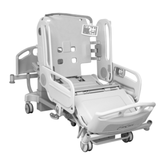
Introduction Chapter 1: Introduction Introduction Overview The AvantGuard™ Electric Bed comprises: • Three adjustable sections: head, thigh and foot. • Height adjustment of the sleep surface level. • Inclination of the bed frame in trendelenburg (head down) or reverse trendelenburg (feet down) The AvantGuard™... - Page 22 Introduction Chapter 1: Introduction Figure 1-4. AvantGuard™ Electric Bed 1680_117 1787_105 Page 1 - 8 AvantGuard™ Electric Bed Service Manual (QD1787)
- Page 23 Introduction Chapter 1: Introduction Table 1-2. AvantGuard™ Electric Bed Feature Identification Letter Description TotalGuard™ Integral Siderail release TotalGuard™ Integral Siderail Control panel on a flexible arm Control pendant MobiBar™ Egress Bar Vertical removable footboard Integral bed extension Bumper at each corner Foot siderail support with trendelenburg/reverse trendelenburg angle and horizontal position indicator Emergency trendelenburg...
-
Page 24: Bed Positions
Introduction Chapter 1: Introduction Bed Positions Figure 1-5. EasyChair™ Automatic Chair Position 1787_115 Figure 1-6. Reverse Trendelenburg 1787_116 Page 1 - 10 AvantGuard™ Electric Bed Service Manual (QD1787) - Page 25 Introduction Chapter 1: Introduction Figure 1-7. Emergency Trendelenburg 1787_117 Figure 1-8. EasyChair™ Automatic Chair Position and Reverse Trendelenburg 1787_118 AvantGuard™ Electric Bed Service Manual (QD1787) Page 1 - 11...
- Page 26 Introduction Chapter 1: Introduction Figure 1-9. Trendelenburg 1787_119 Page 1 - 12 AvantGuard™ Electric Bed Service Manual (QD1787)
- Page 27 Introduction Chapter 1: Introduction Figure 1-10. Hilow Positions High Position Low Position 1787_120 AvantGuard™ Electric Bed Service Manual (QD1787) Page 1 - 13...
-
Page 28: Operating Precautions
Introduction Chapter 1: Introduction Operating Precautions WARNING: Driven bed mechanisms can cause serious injury. Do not operate bed controls until all persons are clear of mechanisms. A bed articulation function can be halted by releasing the control, pressing and holding the switch for the opposite function, or by unplugging the AC power connector. - Page 29 Introduction Chapter 1: Introduction Figure 1-12. Control Pendant LI158Ax 1787_101 Table 1-3. Control Pendant Functions Letter Description Head section raise with automatic contour Head section raise without automatic contour Head section lower with automatic contour LED indicator for locking/unlocking of the function (available for each function) Thigh section raise Thigh section lower...
-
Page 30: Hilow Function
Introduction Chapter 1: Introduction Hilow Function The sleep surface of the AvantGuard™ Electric Bed can be raised or lowered to move the patient or to facilitate getting on/off the bed. The column-based elevation system frees space under the sleep surface and enables trendelenburg/reverse trendelenburg to be obtained automatically by the control unit. -
Page 31: Cpr Emergency Release
Introduction Chapter 1: Introduction movements enlarge the sitting area, reduce pelvic pressure, enable the patient to breathe more easily by reducing abdominal pressure, limit the shearing forces and provide greater support for the head and neck. CPR Emergency Release The AvantGuard™ Electric Bed has an emergency lower function for the HS. The CPR release (M) is situated in the central part of the bed alongside the LCU (K) at either side under the sleep surface. -
Page 32: Automatic Contour
Introduction Chapter 1: Introduction To lower the FS of the LI159Ax model, ensure that the TS is at least at mid-height and press the FS lower button (H) of the control pendant or control panel on a flexible arm. Release the button at the desired angle or when maximum lowering is reached. -
Page 33: Lateral Caregiver Unit
Introduction Chapter 1: Introduction Lateral Caregiver Unit Figure 1-13. Lateral Caregiver Unit with Emergency Trendelenburg Function 1680_102 Figure 1-14. Lateral Caregiver Unit without Emergency Trendelenburg Function 1680_103 Table 1-4. Lateral Caregiver Unit Identification Letter Description Function management opening/trendelenburg reverse trendelenburg access opening Low battery, battery charge LED indicator Emergency trendelenburg function access opening Lateral caregiver unit key storage... - Page 34 Introduction Chapter 1: Introduction The lateral caregiver unit is situated on each side of the bed under the seat section of the sleep surface. The LCU key provides access (A) to the function lockout sequence, validation of the trendelenburg/reverse trendelenburg function and to the emergency trendelenburg function (C) (optional on LI158Ax).
-
Page 35: Totalguard™ Integral Siderails
Introduction Chapter 1: Introduction The sleep surface can be inclined in 2 ways: – in trendelenburg where the head of bed is lowered – in reverse trendelenburg where the foot of bed is lowered The maximum scope of trendelenburg movements is obtained irrespective of the the initial height of the sleep surface. -
Page 36: Brakes
Introduction Chapter 1: Introduction • To store a foot siderail: – With one hand, grip the upper mobile section of the siderail at the foot end of the bed, and with the other hand press the release button of the siderail support (H) then raise the siderail and pivot it towards the head end of the bed. -
Page 37: Headboards And Footboards
Introduction Chapter 1: Introduction raised. In this way the bed can be steered easily by pushing the foot or head end of the bed (depending on the configuration). In order to engage the steering position, raise the brake and steer bar with your foot until it is tilting upwards. -
Page 38: I.v. Pole Sockets
Introduction Chapter 1: Introduction I.V. Pole Sockets The AvantGuard™ Electric Bed has four IVP sockets, placed at each corner of the bed. An I.V. pole (accessory) can be inserted into each socket. The two sockets at the patient’s head also enable a patient helper to be attached. Optional Features Hilow Pedal (Optional or Accessory) The AvantGuard™... - Page 39 Introduction Chapter 1: Introduction To disengage the moving position and enable sideways movements, push the bed sideways and the 5th wheel will automatically unlock. Extension (Optional) The AvantGuard™ Electric Bed is designed for tall patients. The overall length of the bed can be increased significantly by sliding the crossbar of the foot panel along its guide rails.
-
Page 40: Specifications
Specifications Chapter 1: Introduction Specifications Physical Description For the AvantGuard™ Electric Bed specifications, see table 1-5 on page 1-26. Table 1-5. AvantGuard™ Electric Bed Specifications Specification Dimension Overall length in high position (basic 2185 mm ± 5 mm (86") version) Overall length in high position with 2365 mm ±... -
Page 41: Electrical Description
Specifications Chapter 1: Introduction Specification Dimension Sleep surface inclination from the +16°/-16° horizontal: trendelenburg/reverse trendelenburg Maximum height of siderail above sleep 395 mm (15.6") surface Maximum weight of bed (without mattress 150 kg (331 Ib) or accessories) Safe working load 185 kg (408 Ib) Maximum lifted load 250 kg (551 Ib) -
Page 42: Power Supply Unit
Specifications Chapter 1: Introduction Power Supply Unit The AvantGuard™ Electric Bed is equipped with electric actuators for the HS, TS, and FS (except LI158Ax) and HL functions, which are controlled by via the power supply unit. The power supply unit operates with 230VAC 50Hz (for tolerances, see table 3-2 on page 3-10), and can be equipped with a 24VDC battery backup (optional). -
Page 43: Regulations, Standards, And Codes
Specifications Chapter 1: Introduction The motor-driven actuators operate under a nominal 24VDC and have a connecting plug to facilitate removal/replacement should problems arise. Each movement is only possible by keeping the button of the corresponding function pressed (no automatic movement). Depending on the function, a button corresponds to the movement of one or more actuators. -
Page 44: Model Identification
Model Identification Chapter 1: Introduction Model Identification For AvantGuard™ Electric Bed model identification, see table 1-8 on page 1-30. Table 1-8. Model Identification Model Description Number LI158Ax AvantGuard™ Electric Bed without EasyChair™ Automatic Chair function (mechanical FS) LI159Ax AvantGuard™ Electric Bed with EasyChair™ Automatic Chair function (electrical FS) Safety Tips CAUTION:... - Page 45 Safety Tips Chapter 1: Introduction CAUTION: If the sleep surface cannot be raised to mid-height for whatever reason, the arms of the elevation tool must not be positioned at the level of the actuators. Disregarding this caution may cause the head section and foot section actuators to malfunction.
- Page 46 Safety Tips Chapter 1: Introduction SHOCK HAZARD: Electric current flows through the connections when the bed is powered. Disconnect from the power outlet, otherwise personal injury could occur. SHOCK HAZARD: The equipotential link and the grounding of the metal parts of the bed depend on the correct installation of the earth conductor and grounding spring blades.
- Page 47 Safety Tips Chapter 1: Introduction WARNING: This manual describes the overall functions of the AvantGuard™ Electric Bed and their use, but it is in no way intended to replace the user manual, the purpose of which is to describe these functions in detail. For precise information relating to the use of the AvantGuard™...
- Page 48 Safety Tips Chapter 1: Introduction WARNING: Only the facility-authorised maintenance personnel should perform preventive maintenance on the on the AvantGuard™ Electric Bed. Preventive maintenance performed by unauthorised personnel could result in personal injury or equipment damage. WARNING: Only the accessories specifically identified below are authorised to be used on the AvantGuard™...
-
Page 49: Identification And Caution Labels
Identification and Caution Labels Chapter 1: Introduction Identification and Caution Labels Figure 1-16. Identification and Caution Labels 1787_106 1680_107 1680_108 1787_114 1680_118 AvantGuard™ Electric Bed Service Manual (QD1787) Page 1 - 35... -
Page 50: Identification And Caution Labels
Identification and Caution Labels Chapter 1: Introduction 1787_110 Page 1 - 36 AvantGuard™ Electric Bed Service Manual (QD1787) - Page 51 Chapter 2 Troubleshooting Procedures Chapter Contents Getting Started ........... . . 2 - 3 Initial Actions.
-
Page 52: Chapter 2: Troubleshooting Procedures
Chapter 2: Troubleshooting Procedures Steering Malfunction ..........2 - 48 5th Wheel Steering Malfunction . -
Page 53: Getting Started
Getting Started Chapter 2: Troubleshooting Procedures Getting Started Begin each procedure in this chapter with step 1. Follow the sequence outlined (each step assumes that the previous steps are correct). Each step is the normal operational event of the product and can be confirmed by answering Y (yes) or N (no) to the question. -
Page 54: Initial Actions
Initial Actions Chapter 2: Troubleshooting Procedures Initial Actions Use Initial Actions to gather information from operators concerning problems with the AvantGuard™ Electric Bed. Note the symptoms or other information concerning the problem that the operator describes. This information helps identify the probable cause. 1. - Page 55 Initial Actions Chapter 2: Troubleshooting Procedures Problem Solution Trendelenburg/Reverse Trendelenburg Malfunction RAP 2.12 Emergency Trendelenburg Function not Working with Bed Connected to RAP 2.13 AC Power Emergency Trendelenburg Function not Working with the Bed not RAP 2.14 Connected to AC Power Bed Connected to AC Power, Brakes not Applied Detection Malfunction RAP 2.15 CPR Malfunction RAP 2.16...
-
Page 56: Function Checks
Function Checks Chapter 2: Troubleshooting Procedures Function Checks 1. The "Initial Actions" have been performed. ↓ → Go to “Initial Actions” on page 2-4. 2. Apply the brakes on the bed and raise and lock the siderails in the high position with the foot siderails folded. - Page 57 Function Checks Chapter 2: Troubleshooting Procedures The bed rises to the high position without stopping or the audible alarm sounding during the movement. ↓ → Go to RAP 2.4 on page 2-20. 8. Press the lower control of the HL function, then the left and right lower pedal controls.
- Page 58 Function Checks Chapter 2: Troubleshooting Procedures ↓ → Go to RAP 2.7 on page 2-26. 14. Press the lower button of the HS function from its highest position. The HS goes down, then the TS continues to drop when the HS reaches low position.
- Page 59 Function Checks Chapter 2: Troubleshooting Procedures ↓ → Go to RAP 2.11 on page 2-35. 21. If the bed is fitted with a chair function: press the non-chair position button of the bed. The HS, TS and FS sections gradually return to the horizontal as long as the button is pressed.
- Page 60 Function Checks Chapter 2: Troubleshooting Procedures An audible alarm can be heard. ↓ → Go to RAP 2.15 on page 2-42. 27. Set the bar to brake position. The audible alarm stops sounding. ↓ → Go to RAP 2.15 on page 2-42. 28.
- Page 61 Function Checks Chapter 2: Troubleshooting Procedures 33. For beds not equipped with 5th wheel system, set the brake/steer bar to "steer" position and trigger the lengthways locking of the steer caster. The caster locks in the expected position. ↓ → Go to RAP 2.20 on page 2-48. 34.
-
Page 62: Final Actions
Final Actions Chapter 2: Troubleshooting Procedures Final Actions 1. Perform the required preventative maintenance procedures. See “Preventive Maintenance Checklist” on page 6-16. 2. Carry out all necessary administrative tasks. Appendix • A test control unit (P/N AG0061) is recommended for most of the following investigation procedures. -
Page 63: No Functions Work
2.1 No Functions Work Chapter 2: Troubleshooting Procedures No Functions Work NOTE: Identification of components: (see figure 3-1 on page 3-3). NOTE: This RAP assumes that no functions work from the HL pedal, the control pendant or control panel on a flexible arm. NOTE: To access the PSU (see figure 4-9 on page 4-19), and connections (see figure 4-10 on page 4-19). - Page 64 2.1 No Functions Work Chapter 2: Troubleshooting Procedures SHOCK HAZARD: Electric current flows through the connections when the bed is switched on. Trials conducted under these conditions carry a risk of electric shock. Do not touch any wire or terminal which conducts an electric current. a.
- Page 65 2.1 No Functions Work Chapter 2: Troubleshooting Procedures Figure 2-1. Measuring the AC Input Voltage 1680_200 AvantGuard™ Electric Bed Service Manual (QD1787) Page 2 - 15...
-
Page 66: Control Unit Malfunction
2.2 Control Unit Malfunction Chapter 2: Troubleshooting Procedures Control Unit Malfunction NOTE: Identification of components: (see figure 3-1 on page 3-3). NOTE: To access the PSU (see figure 4-9 on page 4-19), and connections (see figure 4-10 on page 4-19). NOTE: Comments: •... - Page 67 2.2 Control Unit Malfunction Chapter 2: Troubleshooting Procedures a. Remove the cover of the PSU using the 13 mm combination spanner (see figure 4-8 on page 4-16) b. Disconnect the LCU (Y) (identify the cable by tracing it from the LCU to the connector).
-
Page 68: Function Management Mode Malfunction
2.3 Function Management Mode Malfunction Chapter 2: Troubleshooting Procedures Function Management Mode Malfunction NOTE: Identification of components: (see figure 3-1 on page 3-3). NOTE: To access the PSU (see figure 4-9 on page 4-19), and connections (see figure 4-10 on page 4-19). NOTE: Comments: •... - Page 69 2.3 Function Management Mode Malfunction Chapter 2: Troubleshooting Procedures 5. Replace the Control Unit (CU) - control pendant (refer to procedure 4.2 on page 4-10) or control panel on a flexible arm (refer to procedure 4.3 on page 4-12) according to the option fitted. 6.
-
Page 70: Hilow Malfunction
2.4 Hilow Malfunction Chapter 2: Troubleshooting Procedures Hilow Malfunction NOTE: Identification of components: (see figure 3-1 on page 3-3). NOTE: To access the PSU (see figure 4-9 on page 4-19), and connections (see figure 4-10 on page 4-19). 1. At least one of the other functions is working. ↓... - Page 71 2.4 Hilow Malfunction Chapter 2: Troubleshooting Procedures ↓ → Go to step 14. 8. The HL fault is only noted on ONE HL pedal. ↓ → Go to step 10. 9. Replace the defective pedal (refer to procedure 4.14 on page 4-48). 10.
-
Page 72: Thigh Section Malfunction
2.5 Thigh Section Malfunction Chapter 2: Troubleshooting Procedures Thigh Section Malfunction NOTE: Identification of components: (see figure 3-1 on page 3-3). NOTE: To access the PSU (see figure 4-9 on page 4-19), and connections (see figure 4-10 on page 4-19). NOTE: Initial conditions: the power-driven FS function works (if this option is fitted on the bed) (see “Function Checks”... - Page 73 2.5 Thigh Section Malfunction Chapter 2: Troubleshooting Procedures ↓ → Contact your national Hill-Rom representative (see the last page of this manual). 7. Go to “Final Actions” on page 2-12. AvantGuard™ Electric Bed Service Manual (QD1787) Page 2 - 23...
-
Page 74: Head Section Malfunction (Excluding Automatic Contour)
2.6 Head Section Malfunction (excluding Automatic Contour) Chapter 2: Troubleshooting Procedures Head Section Malfunction (excluding Automatic Contour) NOTE: Identification of components: (see figure 3-1 on page 3-3). NOTE: To access the PSU (see figure 4-9 on page 4-19), and connections (see figure 4-10 on page 4-19). - Page 75 2.6 Head Section Malfunction (excluding Automatic Contour) Chapter 2: Troubleshooting Procedures 5. The PSU is defective. Replace it (refer to procedure 4.5 on page 4-18). This solves the problem. ↓ → Contact your national Hill-Rom representative (see the last page of this manual).
-
Page 76: Automatic Contour Malfunction
2.7 Automatic Contour Malfunction Chapter 2: Troubleshooting Procedures Automatic Contour Malfunction NOTE: Identification of components: (see figure 3-1 on page 3-3). NOTE: To access the PSU (see figure 4-9 on page 4-19), and connections (see figure 4-10 on page 4-19). NOTE: Initial conditions: a. - Page 77 2.7 Automatic Contour Malfunction Chapter 2: Troubleshooting Procedures ↓ → Replace the PSU (refer to procedure 4.5 on page 4-18). 6. The problem is due to incorrect usage. 7. Troubleshoot using the following two possibilities. a. A new actuator or a TS and FS actuator simulation connector (P/N AG0063, see “Appendix”...
- Page 78 2.7 Automatic Contour Malfunction Chapter 2: Troubleshooting Procedures The TS section raises or lowers until mid-travel then stops. ↓ → Go to step 14. 13. The problem is due to incorrect usage. 14. Switching the connectors of the TS/FS actuators: Switch the connectors of the TS and FS actuators (#2, green and #5, brown) a.
-
Page 79: Battery Backup Malfunction
2.8 Battery Backup Malfunction Chapter 2: Troubleshooting Procedures Battery Backup Malfunction NOTE: Identification of components: (see figure 3-1 on page 3-3). NOTE: To access the PSU (see figure 4-9 on page 4-19), and connections (see figure 4-10 on page 4-19). Initial conditions: the bed works normally when connected to an appropriate power source (see “Function Checks”... - Page 80 2.8 Battery Backup Malfunction Chapter 2: Troubleshooting Procedures ↓ → Replace the PSU (refer to procedure 4.5 on page 4-18). If this solves the problem perform the “Final Actions” on page 2-12, otherwise contact your national Hill-Rom representative (see the last page of this manual).
-
Page 81: Foot Section Malfunction
2.9 Foot Section Malfunction Chapter 2: Troubleshooting Procedures Foot Section Malfunction NOTE: Identification of components: (see figure 3-1 on page 3-3). NOTE: To access the PSU (see figure 4-9 on page 4-19), and connections (see figure 4-10 on page 4-19). NOTE: Initial conditions: the TS actuator movements are working (retraction and extension) and the actuator (rod) is in extended position. - Page 82 2.9 Foot Section Malfunction Chapter 2: Troubleshooting Procedures 8. Test the function of the TS actuator intermediate switch. a. Connect the FS actuator cable to its socket (#2, green). b. Either connect new TS actuator in extended position – or connect a TS actuator simulation connector RC (P/N AG0063, see “Appendix”...
- Page 83 2.9 Foot Section Malfunction Chapter 2: Troubleshooting Procedures ↓ → Contact your national Hill-Rom representative (see the last page of this manual). 13. Go to “Final Actions” on page 2-12. AvantGuard™ Electric Bed Service Manual (QD1787) Page 2 - 33...
-
Page 84: 2.10 Assisted Foot Section Malfunction
2.10 Assisted Foot Section Malfunction Chapter 2: Troubleshooting Procedures 2.10 Assisted Foot Section Malfunction NOTE: Identification of components: (see figure 3-1 on page 3-3). NOTE: Initial conditions: the TS function is working. 1. Verify the attachment of the TS and the FS. Remove the hard surfaces of the TS and FS. -
Page 85: 2.11 Easychair™ Automatic Chair Position Malfunction
2.11 EasyChair™ Automatic Chair Position Malfunction Chapter 2: Troubleshooting Procedures 2.11 EasyChair™ Automatic Chair Position Malfunction NOTE: Identification of components: (see figure 3-1 on page 3-3). NOTE: To access the PSU (see figure 4-9 on page 4-19), and connections (see figure 4-10 on page 4-19). -
Page 86: 2.12 Trendelenburg/Reverse Trendelenburg Malfunction
2.12 Trendelenburg/Reverse Trendelenburg Malfunction Chapter 2: Troubleshooting Procedures 2.12 Trendelenburg/Reverse Trendelenburg Malfunction NOTE: Identification of components: (see figure 3-1 on page 3-3). NOTE: To access the PSU (see figure 4-9 on page 4-19), and connections (see figure 4-10 on page 4-19). NOTE: Initial conditions: the HL function works (see “Function Checks”... -
Page 87: 2.13 Emergency Trendelenburg Function Not Working With Bed
2.13 Emergency Trendelenburg Function not Working with Bed Connected to AC Power Chapter 2: Troubleshooting Procedures 2.13 Emergency Trendelenburg Function not Working with Bed Connected to AC Power NOTE: Identification of components: (see figure 3-1 on page 3-3). NOTE: To access the PSU (see figure 4-9 on page 4-19), and connections (see figure 4-10 on page 4-19). - Page 88 2.13 Emergency Trendelenburg Function not Working with Bed Connected to AC Power Chapter 2: Troubleshooting Procedures page 2-12, otherwise contact your national Hill-Rom representative (see the last page of this manual). 6. Replace the defective LCU (refer to procedure 4.7 on page 4-25). This solves the problem.
-
Page 89: Emergency Trendelenburg Function Not Working With The Bed Not
2.14 Emergency Trendelenburg Function not Working with the Bed not Connected to AC Power Chapter 2: Troubleshooting Procedures 2.14 Emergency Trendelenburg Function not Working with the Bed not Connected to AC Power NOTE: Identification of components: (see figure 3-1 on page 3-3). NOTE: To access the PSU (see figure 4-9 on page 4-19), and connections (see figure 4-10 on page 4-19). - Page 90 2.14 Emergency Trendelenburg Function not Working with the Bed not Connected to AC Power Chapter 2: Troubleshooting Procedures 5. Go to “Final Actions” on page 2-12. 6. Replace the battery pack of the emergency trendelenburg function with a new one (refer to procedure 4.6 on page 4-22). The emergency trendelenburg function works.
- Page 91 2.14 Emergency Trendelenburg Function not Working with the Bed not Connected to AC Power Chapter 2: Troubleshooting Procedures page 2-12, otherwise contact your national Hill-Rom representative (see the last page of this manual). 12. Go to “Final Actions” on page 2-12. AvantGuard™...
-
Page 92: Bed Connected To Ac Power, Brakes Not Applied Detection Malfunction
2.15 Bed Connected to AC Power, Brakes not Applied Detection Malfunction Chapter 2: Troubleshooting Procedures 2.15 Bed Connected to AC Power, Brakes not Applied Detection Malfunction NOTE: Identification of components: (see figure 3-1 on page 3-3). NOTE: To access the PSU (see figure 4-9 on page 4-19), and connections (see figure 4-10 on page 4-19). - Page 93 2.15 Bed Connected to AC Power, Brakes not Applied Detection Malfunction Chapter 2: Troubleshooting Procedures c. The same verification applies to the terminals of the 8-pin connector in the central rail of the bed frame by checking the operation of the BM from terminals 1 and 6 of the F-Col (see figure 2-3 on page 2-43).
-
Page 94: 2.16 Cpr Malfunction
2.16 CPR Malfunction Chapter 2: Troubleshooting Procedures 2.16 CPR Malfunction NOTE: Identification of components: (see figure 3-1 on page 3-3). NOTE: Initial conditions: the HL function works (see “Function Checks” on page 2-6). 1. Check the mechanics of the CPR system. Remove the hard surfaces of the SS, the TS and the FS (refer to procedure 4.1 on page 4-5). -
Page 95: 2.17 Foot Siderail Locking/Unlocking Malfunction
2.17 Foot Siderail Locking/Unlocking Malfunction Chapter 2: Troubleshooting Procedures 2.17 Foot Siderail Locking/Unlocking Malfunction NOTE: Identification of components: (see figure 3-1 on page 3-3). NOTE: Initial conditions: the HL function works (see “Function Checks” on page 2-6). 1. Perform the following to check the foot siderail support. a. -
Page 96: 2.18 Head Siderail Locking/Unlocking Malfunction
2.18 Head Siderail Locking/Unlocking Malfunction Chapter 2: Troubleshooting Procedures 2.18 Head Siderail Locking/Unlocking Malfunction NOTE: Identification of components: (see figure 3-1 on page 3-3). NOTE: Initial conditions: the foot siderails are working (see “Function Checks” on page 2-6). 1. Check the locking and unlocking of the head siderail of the bed. Set the foot siderail to folded position. -
Page 97: 2.19 Braking Malfunction
2.19 Braking Malfunction Chapter 2: Troubleshooting Procedures 2.19 Braking Malfunction NOTE: Identification of components: (see figure 3-1 on page 3-3). NOTE: Initial conditions: none 1. Check the caster attachment. Check that the screws or supports are not damaged, loose or missing from the caster attachments (refer to the assembly diagrams of chapter 5). -
Page 98: 2.20 Steering Malfunction
2.20 Steering Malfunction Chapter 2: Troubleshooting Procedures 2.20 Steering Malfunction NOTE: Identification of components: (see figure 3-1 on page 3-3). NOTE: Initial conditions: none. 1. Check the caster attachment. Set the brake/steer bar to brake position. Check that the screws or supports are not damaged, loose or missing from the caster attachments, (refer to the assembly diagrams of chapter 5). -
Page 99: 2.21 5Th Wheel Steering Malfunction
2.21 5th Wheel Steering Malfunction Chapter 2: Troubleshooting Procedures 2.21 5th Wheel Steering Malfunction NOTE: Identification of components: (see figure 3-1 on page 3-3). Initial conditions: none. 1. Check the attachment of the 5th wheel. Check that the screws or supports are not damaged, loose or missing from the support (5th wheel) and caster attachments, (refer to the assembly diagrams of chapter 5). - Page 100 2.21 5th Wheel Steering Malfunction Chapter 2: Troubleshooting Procedures ↓ → Contact your national Hill-Rom representative (see the last page of this manual). 8. Go to “Final Actions” on page 2-12. Page 2 - 50 AvantGuard™ Electric Bed Service Manual (QD1787)
- Page 101 Chapter 3 Theory of Operation Chapter Contents Component Positioning and Electrical Diagrams - LI158Ax/LI159Ax ..3 - 3 Theory of Operation..........3 - 6 Mechanical System .
- Page 102 Chapter 3: Theory of Operation Detection of Bed not in Low Position....... 3 - 15 Automatic Contour .
-
Page 103: Chapter 3: Theory Of Operation
Component Positioning and Electrical Diagrams - LI158Ax/LI159Ax Chapter 3: Theory of Operation Component Positioning and Electrical Diagrams - LI158Ax/LI159Ax Figure 3-1. Component Positioning - LI158Ax/LI159Ax Control pendant Control panel on a flexible Footboard Linen holder (not visible) Headboard Foot siderail support Hilow columns Lateral caregiver... - Page 104 Component Positioning and Electrical Diagrams - LI158Ax/LI159Ax Chapter 3: Theory of Operation Figure 3-2. Wiring Schematic for LI158Ax H-Col Management Battery indicator mode Emergency Emergency trendelenburg trendelenburg (optional) (optional) Battery indicator Management mode Control Control pendant panel on a flexible (optional) HL pedal HL pedal...
- Page 105 Component Positioning and Electrical Diagrams - LI158Ax/LI159Ax Chapter 3: Theory of Operation Figure 3-3. Wiring Schematic for LI159Ax H-Col Management mode Battery indicator Emergency Emergency trendelenburg trendelenburg Management Battery indicator mode Control pendant Control panel on a flexible HL pedal HL pedal (optional) F-Col...
-
Page 106: Theory Of Operation
Theory of Operation Chapter 3: Theory of Operation Theory of Operation The operation of the AvantGuard™ Electric Bed is divided into 2 sub-systems: • Electrical • Mechanical The interaction between these sub-systems allows all the operational functions to be used. The electric functions are driven by low voltage actuators. -
Page 107: Mechanical System
Mechanical System Chapter 3: Theory of Operation Mechanical System The mechanical sub-system consists of two connected systems: • Bed frame • Sleep surface Retractable Head Section The retractable head section feature is achieved by controlling a sliding movement of the HS frame with two sliding blocks in channels at each side of the intermediate frame which causes the HS frame to extend (with respect to the SS). -
Page 108: Casters
Mechanical System Chapter 3: Theory of Operation Casters The bed has four casters, three brake and one brake/steer, each with a 30° inclination activation mechanism and three positions: • Brake caster: Brake/Neutral/Neutral positions • Steer caster: Brake/Neutral/Steer positions Antistatic brake casters are available as an option. They are always fitted in pairs when this option is installed and are identified by a yellow dot on the tyre (single band) or in the centre of each caster (double band). -
Page 109: Totalguard™ Integral Siderail Construction
Mechanical System Chapter 3: Theory of Operation TotalGuard™ Integral Siderail Construction The siderail subassemblies comprise two head and foot sections in fire-resistant extruded/blow-moulded polypropylene and a metal support of the malleable parallelogram type. • Each head siderail integrates a double security release system. •... -
Page 110: Electrical System
Electrical System Chapter 3: Theory of Operation Electrical System The specifications of the bed are as follows: Table 3-1. Specifications of the LI158Ax/LI159Ax Bed Description Specification Type AvantGuard™ Electric Bed Reference LI158Ax, LI159Ax Type of protection against electric shock Class I (according to IEC 60601-1) Degree of protection against electric shock Type B... -
Page 111: Power Stage
Electrical System Chapter 3: Theory of Operation The power supply unit comprises of the following main sections: • Power stage • Functions controlled by relays and transistors • Battery charging circuit • Control logic and specific functions The functions are activated after electronically unlocking each of them by using one of the following: •... -
Page 112: Battery Circuit
Electrical System Chapter 3: Theory of Operation Battery Circuit The bed can be fitted with a battery backup (optional) and/or an emergency trendelenburg function battery backup (optional). These batteries are internal to the power supply unit. The emergency trendelenburg function battery is only available for this specific function. -
Page 113: Control Logic And Specific Functions
Electrical System Chapter 3: Theory of Operation Description Specification Discharging time (storage), battery Minimum 10 days connected to bed Discharging time (storage), battery not 3 months connected to bed These are sealed lead acid batteries connected in series on the main board and protected by fuses on the connection wires. -
Page 114: Control Pendant
Electrical System Chapter 3: Theory of Operation All of these functions are integrated into a CPLD (Complex Programmable Logic Device). Control Pendant The control pendant is available in two configurations depending on the bed model. Each unit operates at 3.3VDC supplied by the power card and integrates three main principles: •... -
Page 115: Motor Characteristics
Electrical System Chapter 3: Theory of Operation Motor Characteristics The motors have the following characteristics: Table 3-5. Motor Characteristics and Dimensions HL column Description HS motor TS motor FS motor motor Power 96 W (x2) 120 W 84 W 84 W Voltage 18 to 40VDC 18 to 40VDC... -
Page 116: Automatic Contour
Electrical System Chapter 3: Theory of Operation Automatic Contour The PSU, when it received a command from the CU, controls the automatic contour (HS and TS) operation of the bed. This function is carried out through an intermediate switch of the TS actuator. When the HS raise function is activated from the horizontal position, the HS and TS rise immediately until the intermediate internal microswitch of the TS actuator cuts its power at approximately 20°. - Page 117 Electrical System Chapter 3: Theory of Operation NOTE: The warranty will be rendered null and void if any electrical component is opened, except where the PSU cover is removed by authorised personnel. AvantGuard™ Electric Bed Service Manual (QD1787) Page 3 - 17...
- Page 118 Electrical System Chapter 3: Theory of Operation NOTES: Page 3 - 18 AvantGuard™ Electric Bed Service Manual (QD1787)
- Page 119 Chapter 4 Removal, Replacement and Adjustment Procedures Chapter Contents Bed Frame Hard Surface Replacement ........4 - 5 Removal .
-
Page 120: Chapter 4: Removal, Replacement And Adjustment Procedures
Chapter 4: Removal, Replacement and Adjustment Procedures Removal ........... . . 4 - 30 Replacement . - Page 121 Chapter 4: Removal, Replacement and Adjustment Procedures Replacement........... 4 - 64 Gas Spring Subassembly with Cable and Foot Section Sleeve (LI158Ax only) .
- Page 122 Chapter 4: Removal, Replacement and Adjustment Procedures NOTES : Page 4 - 4 AvantGuard™ Electric Bed Service Manual (QD1787)
-
Page 123: Bed Frame Hard Surface Replacement
4.1 Bed Frame Hard Surface Replacement Chapter 4: Removal, Replacement and Adjustment Procedures Bed Frame Hard Surface Replacement Time required: 10 min Number of people: 1 (plus 1 occasionally) Possibility of intervening with patient on the bed: No Tools required: #2 phillips head screwdriver—control panel on a flexible arm only Removal... - Page 124 4.1 Bed Frame Hard Surface Replacement Chapter 4: Removal, Replacement and Adjustment Procedures 4. For the TS hard surface, grip the hard surface (B) on either side of the sleep surface and remove it from the bed. 5. For the SS hard surface, grip the hard surface (C) on either side of the sleep surface and remove it from the bed.
-
Page 125: Replacement
4.1 Bed Frame Hard Surface Replacement Chapter 4: Removal, Replacement and Adjustment Procedures Figure 4-3. Installing the Head Section Hard Surface 1680_409 d. Manually move the brackets (H) on each side of the HS hard surface and slightly raise the hard surface (photo shown with HS section lifted for clarity) (see figure 4-4 on page 4-7). - Page 126 4.1 Bed Frame Hard Surface Replacement Chapter 4: Removal, Replacement and Adjustment Procedures CAUTION: The head section must always be horizontal when removing or fitting the head section hard surface. Failure to do so may give rise to an incorrect position and cause the elevation sliding system to malfunction.
- Page 127 4.1 Bed Frame Hard Surface Replacement Chapter 4: Removal, Replacement and Adjustment Procedures 3. Grip the end handles of the HS hard surface, operate one of the CPR handles and raise/lower the HS to check that the hard surface moves without interference.
-
Page 128: Control Pendant
4.2 Control Pendant Chapter 4: Removal, Replacement and Adjustment Procedures Control Pendant Identification: (see figure 3-1 on page 3-3) Time required: 5 min Number of people: 1 Possibility of intervening with patient on the bed: Yes Tools required: None Removal 1. -
Page 129: Replacement
4.2 Control Pendant Chapter 4: Removal, Replacement and Adjustment Procedures Figure 4-6. Control Pendant Connection 1680_425 6. Disconnect the connector (A) from the LCU by pulling (no specific locking). The cable does not pass through the conduit located under the crossbar (B) (see figure 4-6 on page 4-11). -
Page 130: Control Panel On A Flexible Arm
4.3 Control Panel on a Flexible Arm Chapter 4: Removal, Replacement and Adjustment Procedures Control Panel on a Flexible Arm Identification: (see figure 3-1 on page 3-3) Time required: 15 min Number of people: 1 (plus 1 occasionally) Possibility of intervening with patient on the bed: No Tools required: #2 phillips head screwdriver Removal... -
Page 131: Replacement
4.3 Control Panel on a Flexible Arm Chapter 4: Removal, Replacement and Adjustment Procedures Figure 4-7. Installing the Control Panel on a Flexible Arm 1680_403 6. Remove the hard surfaces of the SS and the TS (refer to procedure 4.1). 7. - Page 132 4.3 Control Panel on a Flexible Arm Chapter 4: Removal, Replacement and Adjustment Procedures CAUTION: The head section must always be horizontal when removing or fitting the head section hard surface. Failure to do so may give rise to an incorrect position and cause the elevation sliding system to malfunction.
-
Page 133: Ac Power Cable
4.4 AC Power Cable Chapter 4: Removal, Replacement and Adjustment Procedures AC Power Cable Identification: (see figure 3-1 on page 3-3). WARNING: Only the AC power cables listed in chapter 5 can be used on the AvantGuard™ Electric Bed. Other cables may compromise the safety and conformity of the bed. -
Page 134: Replacement
4.4 AC Power Cable Chapter 4: Removal, Replacement and Adjustment Procedures Figure 4-8. Installing the AC Power Cable 1680_423 7. Note the passage of the AC power cable, and the connection of the wires on the AC input terminal (E) inside the PSU (see figure 4-10 on page 4-19). 8. - Page 135 4.4 AC Power Cable Chapter 4: Removal, Replacement and Adjustment Procedures SHOCK HAZARD: An abnormally high leakage current is symptomatic of a degradation within the AC power cable and the PSU. Personal injury could result if the value of the leakage current is above 500 microamperes. 4.
-
Page 136: Power Supply Unit
4.5 Power Supply Unit Chapter 4: Removal, Replacement and Adjustment Procedures Power Supply Unit Identification: (see figure 3-1 on page 3-3) Time required: 20 min Number of people: 1 Possibility of intervening with patient on the bed: No Tools required: 13 mm ratchet wrench NOTE: The batteries are not supplied with the PSU. - Page 137 4.5 Power Supply Unit Chapter 4: Removal, Replacement and Adjustment Procedures Figure 4-9. Power Supply Unit Cover 1680_426 4. Note the passage of the cables in the PSU, and their connection on the main board (D) and the AC input terminal (E) (see figure 4-10 on page 4-19). Figure 4-10.
-
Page 138: Replacement
4.5 Power Supply Unit Chapter 4: Removal, Replacement and Adjustment Procedures Table 4-1. Power Supply Unit Connections Connector Marking Colour Identification number Not used Grey Right hand LCU Grey Left hand LCU Green Foot section actuator Blue Foot section actuator Yellow Foot hilow column Brown... - Page 139 4.5 Power Supply Unit Chapter 4: Removal, Replacement and Adjustment Procedures SHOCK HAZARD: An abnormally high leakage current is symptomatic of a degradation within the AC power cable and the PSU. Personal injury could result if the value of the leakage current is above 500 microamperes. 4.
-
Page 140: Battery Backup And Emergency Trendelenburg Function
4.6 Battery Backup and Emergency Trendelenburg Function Chapter 4: Removal, Replacement and Adjustment Procedures Battery Backup and Emergency Trendelenburg Function Identification: The batteries are located in the PSU (see figure 3-1 on page 3-3) Time required: 10 min Number of people: 1 Possibility of intervening with patient on the bed: No Tools required: 13 mm ratchet wrench... -
Page 141: Replacement
4.6 Battery Backup and Emergency Trendelenburg Function Chapter 4: Removal, Replacement and Adjustment Procedures Figure 4-11. Battery Backup Connections 1680_427 Replacement 1. Perform the removal in reverse order, while ensuring that the correct polarities are used when connecting new batteries. NOTE: To prevent connection errors, the connections of the battery backup and the emergency trendelenburg function battery are different. - Page 142 4.6 Battery Backup and Emergency Trendelenburg Function Chapter 4: Removal, Replacement and Adjustment Procedures 3. The batteries should be fully recharged at the end of the test or if the low batery signal is heard during the tests. 4. Perform the “Function Checks” on page 2-6. Page 4 - 24 AvantGuard™...
-
Page 143: Lateral Caregiver Unit
4.7 Lateral Caregiver Unit Chapter 4: Removal, Replacement and Adjustment Procedures Lateral Caregiver Unit Identification: (see figure 3-1 on page 3-3) Time required: 15 min Number of people: 1 Possibility of intervening with patient on the bed: No Tools required: 13 mm ratchet wrench Removal 1. -
Page 144: Replacement
4.7 Lateral Caregiver Unit Chapter 4: Removal, Replacement and Adjustment Procedures Figure 4-12. Installing the Lateral Caregiver Unit 1680_424 8. Disconnect the connector (F) of the control pendant or control panel on a flexible arm if this is connected to the LCU that is to be replaced (see figure 4-12 on page 4-26). -
Page 145: Head Section Actuator
4.8 Head Section Actuator Chapter 4: Removal, Replacement and Adjustment Procedures Head Section Actuator Identification: (see figure 3-1 on page 3-3) For clarity, two separate procedures are used for the removal of the HS actuator and its CPR release cable. However, they are part of the same kit (one reference available). - Page 146 4.8 Head Section Actuator Chapter 4: Removal, Replacement and Adjustment Procedures 8. With the two 10 mm combination spanners, loosen the adjuster (E) (see figure 4-13 on page 4-28). NOTE: Adjusting the CPR cable involves compensating the play at the level of the CPR handle and the HS actuator by the adjuster, without creating any previous tension of the cable.
-
Page 147: Replacement
4.8 Head Section Actuator Chapter 4: Removal, Replacement and Adjustment Procedures 11. Remove the cable and its pivoting attachment from the release cam (G). NOTE: The release cam (G) has a slot enabling the cable to pass. This slot must always point toward the articulation (centre of the motor) when installing so as to prevent it from retracting when in use. -
Page 148: Head Section Release Cable
4.9 Head Section Release Cable Chapter 4: Removal, Replacement and Adjustment Procedures Head Section Release Cable Identification: (see figure 3-1 on page 3-3) NOTE: The HS release cable is a Y-cable common to the two CPR handles. The two uncovered branches are, however, of different lengths. Time required: Time required: 15 min Number of people: 1... -
Page 149: Replacement
4.9 Head Section Release Cable Chapter 4: Removal, Replacement and Adjustment Procedures 5. Pull on the CPR cable sleeving to separate the adjuster (E) from its support. 6. Using the two 10 mm combination spanners, loosen the nut of the sleeving stop (F) and free the CPR cable from its guide on the actuator (see figure 4-14 on page 4-28). - Page 150 4.9 Head Section Release Cable Chapter 4: Removal, Replacement and Adjustment Procedures NOTE: There should not be any tension on the cable, merely compensation for the play at the level of the CPR handles and the HS actuator. 3. Lock the nuts using the two 10 mm combination spanners. 4.
-
Page 151: 4.10 Thigh Section Actuator
4.10 Thigh Section Actuator Chapter 4: Removal, Replacement and Adjustment Procedures 4.10 Thigh Section Actuator Identification: (see figure 3-1 on page 3-3) Time required: 15 min Number of people: 1 Possibility of intervening with patient on the bed: No Tools required: 13 mm ratchet wrench Removal 1. -
Page 152: Replacement
4.10 Thigh Section Actuator Chapter 4: Removal, Replacement and Adjustment Procedures Figure 4-17. Thigh Section actuator 1680_430 8. Remove the Truarc® circlips from the pin supporting the TS actuator, and remove the pin while supporting the actuator. Replacement 1. Perform the removal procedure in reverse order. CAUTION: Ensure that the elastic found on the new actuators is not wound around the actuator body before removing it (cut). -
Page 153: Foot Section Actuator Replacement (Li159Ax Only)
4.11 Foot Section Actuator Replacement (LI159Ax only) Chapter 4: Removal, Replacement and Adjustment Procedures 4.11 Foot Section Actuator Replacement (LI159Ax only) Identification: (see figure 3-1 on page 3-3) Time required: 20 min Number of people: 1 Possibility of intervening with patient on the bed: No Tools required: 13 mm ratchet wrench Removal... -
Page 154: Replacement
4.11 Foot Section Actuator Replacement (LI159Ax only) Chapter 4: Removal, Replacement and Adjustment Procedures Figure 4-18. Foot Section Actuator 1680_407 8. Remove the pin while supporting the FS and the FS actuator. 9. Remove the Truarc® circlips from the pin supporting the FS actuator body and remove the pin from the actuator. -
Page 155: 4.12 Head Hilow Column
4.12 Head Hilow Column Chapter 4: Removal, Replacement and Adjustment Procedures 4.12 Head Hilow Column Identification: (see figure 3-1 on page 3-3) Time required: 40 min Number of people: 1 Possibility of intervening with patient on the bed: No Tools required: 13 mm ratchet wrench with extension Elevation tool (P/N AG0052) Removal... - Page 156 4.12 Head Hilow Column Chapter 4: Removal, Replacement and Adjustment Procedures Figure 4-19. Head HL Column Supply 1680_400 7. Disconnect the earthing conductor (D) of the H-Col by unclipping it from the AC input board (see figure 4-19 on page 4-38). 8.
- Page 157 4.12 Head Hilow Column Chapter 4: Removal, Replacement and Adjustment Procedures CAUGHT HAZARD: The elevation tool must be used to remove the column in safety. Use the elevation tool, otherwise personal injury could occur. 9. Position the elevation tool at the level of the guide arms (E) and adjust the arms to the height corresponding to the bed frame.
-
Page 158: Replacement
4.12 Head Hilow Column Chapter 4: Removal, Replacement and Adjustment Procedures Replacement SHOCK HAZARD: The equipotential link and the grounding of the metal parts of the bed depend on the correct installation of the earth conductor and grounding spring blades. Personal injury could result if the installation is not correct and/or if the earth continuity is compromised. - Page 159 4.12 Head Hilow Column Chapter 4: Removal, Replacement and Adjustment Procedures SHOCK HAZARD: The equipotential link and the grounding of the metal parts of the bed depend on the correct installation of the earth conductor and grounding spring blades. Personal injury could result if the installation is not correct and/or if the earth continuity is compromised.
-
Page 160: 4.13 Foot Hilow Column
4.13 Foot Hilow Column Chapter 4: Removal, Replacement and Adjustment Procedures 4.13 Foot Hilow Column Identification: (see figure 3-1 on page 3-3) Time required: 40 min Number of people: 1 Possibility of intervening with patient on the bed: No Tools required: 13 mm ratchet wrench with extension Elevation tool (P/N AG0052) Removal... - Page 161 4.13 Foot Hilow Column Chapter 4: Removal, Replacement and Adjustment Procedures Figure 4-21. Foot Hilow Column Connection 1680_431 7. Perform the following if the bed is imobilised in the low position: a. Plug the bed into an appropriate power source, and lockout all the functions except the HL function.
- Page 162 4.13 Foot Hilow Column Chapter 4: Removal, Replacement and Adjustment Procedures Figure 4-22. Foot Hilow Column Base 1680_432 9. Open the cable tracks situated under the foot crossbar of the frame and free the cables. CAUGHT HAZARD: The elevation tool must be used to remove the column in safety. Use the elevation tool, otherwise personal injury could occur.
- Page 163 4.13 Foot Hilow Column Chapter 4: Removal, Replacement and Adjustment Procedures Figure 4-23. Foot Section Support 1680_443 12. Using the 13 mm ratchet wrench, loosen and remove the 4 screws (I) securing the base of the HL column (see figure 4-24 on page 4-45). NOTE: For example, the photo shows an HL column with the 45 to 85 cm option.
-
Page 164: Replacement
4.13 Foot Hilow Column Chapter 4: Removal, Replacement and Adjustment Procedures 14. Using the 13 mm ratchet wrench, loosen and remove the four screws (L) on each side of the column and recover the grounding spring (M). 15. Slightly raise the bed frame foot section using the elevation tool, tilt the column outwards then slide its upper section so as to remove it from the guide rails. - Page 165 4.13 Foot Hilow Column Chapter 4: Removal, Replacement and Adjustment Procedures 9. Operate the trendelenburg function of the bed to ensure that there is no tension on the power supply cable of the column during operation. If necessary, adjust the play of the cable with respect to the PSU. SHOCK HAZARD: The equipotential link and the grounding of the metal parts of the bed depend on the correct installation of the earth conductor and grounding...
-
Page 166: 4.14 Hilow Pedal
4.14 Hilow Pedal Chapter 4: Removal, Replacement and Adjustment Procedures 4.14 Hilow Pedal Identification: (see figure 3-1 on page 3-3) Time required: 15 min Number of people: 1 Possibility of intervening with patient on the bed: Yes Tools required: Small screwdriver 13 mm ratchet wrench Removal NOTE:... -
Page 167: Replacement
4.14 Hilow Pedal Chapter 4: Removal, Replacement and Adjustment Procedures Replacement 1. Perform the removal procedure in reverse order. 2. Perform the “Function Checks” on page 2-6. AvantGuard™ Electric Bed Service Manual (QD1787) Page 4 - 49... -
Page 168: Replacement Of Microswitch Assembly For Bed Braking Detection
4.15 Replacement of Microswitch Assembly for Bed Braking Detection Chapter 4: Removal, Replacement and Adjustment Procedures 4.15 Replacement of Microswitch Assembly for Bed Braking Detection Identification: (see figure 3-1 on page 3-3) Time required: 15 min Number of people: 1 Possibility of intervening with patient on the bed: Yes Tools required: Small screwdriver... -
Page 169: Replacement
4.15 Replacement of Microswitch Assembly for Bed Braking Detection Chapter 4: Removal, Replacement and Adjustment Procedures Figure 4-25. Braking Detection Microswitch Replacement 1. Perform the removal procedure in reverse order. 2. Perform the “Function Checks” on page 2-6. AvantGuard™ Electric Bed Service Manual (QD1787) Page 4 - 51... -
Page 170: 4.16 Single Brake Bar
4.16 Single Brake Bar Chapter 4: Removal, Replacement and Adjustment Procedures 4.16 Single Brake Bar Identification: (see figure 3-1 on page 3-3) Time required: 40 min Number of people: 1 Possibility of intervening with patient on the bed: No Tools required: 13 mm ratchet wrench 10 mm Allen™... - Page 171 4.16 Single Brake Bar Chapter 4: Removal, Replacement and Adjustment Procedures CAUTION: If the sleep surface cannot be raised to mid-height for whatever reason, the arms of the elevation tool must not be positioned at the level of the actuators. Disregarding this caution may cause the head section and foot section actuators to malfunction.
- Page 172 4.16 Single Brake Bar Chapter 4: Removal, Replacement and Adjustment Procedures Figure 4-27. Braking Bar Stop 1680_051 6. Adjust the elevation tool so as to lift the frame by a few centimetres. 7. Using the 13 mm ratchet wrench, loosen the 4 screws (C) securing the head and foot end casters on the right hand side of the frame.
-
Page 173: Replacement
4.16 Single Brake Bar Chapter 4: Removal, Replacement and Adjustment Procedures 9. Remove the caster plus support assembly (D) by using the soft faced hammer (see figure 4-27 on page 4-54). NOTE: Do not rotate the casters in their sockets. This is to retain the adjustment. 10. -
Page 174: 4.17 Caster, Brake And Steer Caster
4.17 Caster, Brake and Steer Caster Chapter 4: Removal, Replacement and Adjustment Procedures 4.17 Caster, Brake and Steer Caster Identification: (see figure 3-1 on page 3-3) Time required: 15 min (without adjustment) Number of people: 1 Possibility of intervening with patient on the bed: No Tools required: 13 mm ratchet wrench 10 mm Allen™... - Page 175 4.17 Caster, Brake and Steer Caster Chapter 4: Removal, Replacement and Adjustment Procedures WARNING: Never lift the entire bed with the elevation tool. Its maximum load is 150kg. Disregarding this warning may cause the elevation mechanism to malfunction and could cause injury. CAUTION: If the sleep surface cannot be raised to mid-height for whatever reason, the arms of the elevation tool must not be positioned at the level of the...
-
Page 176: Replacement
4.17 Caster, Brake and Steer Caster Chapter 4: Removal, Replacement and Adjustment Procedures Replacement 1. Before installing the new caster, set the single brake bar to brake position, then steer position. Note the direction of rotation of the hexagonal bar when moving from one position to the other, then reset the bar to neutral. -
Page 177: Adjustment: Single And Double Band Casters
4.17 Caster, Brake and Steer Caster Chapter 4: Removal, Replacement and Adjustment Procedures Adjustment: Single and Double Band Casters Time required: 10 min per caster Number of people: 1 Possibility of intervening with patient on the bed: No Tools required: 13 mm ratchet wrench 10 mm Allen™... -
Page 178: Steer Caster
4.17 Caster, Brake and Steer Caster Chapter 4: Removal, Replacement and Adjustment Procedures e. Refit the caster covers. Figure 4-30. Caster 1680_416 5. Depending on the caster type, adjust the caster body as follows: a. Non-antistatic single band caster: 4 half-turns clockwise (viewed from above). -
Page 179: 4.18 5Th Wheel Steering System
4.18 5th Wheel Steering System Chapter 4: Removal, Replacement and Adjustment Procedures 4.18 5th Wheel Steering System Identification: (see figure 3-1 on page 3-3) Time required: 20 min Number of people: 1 Possibility of intervening with patient on the bed: No Tools required: 13 mm ratchet wrench 13 mm combination spanner... -
Page 180: Replacement
4.18 5th Wheel Steering System Chapter 4: Removal, Replacement and Adjustment Procedures Figure 4-31. Installing the 5th Wheel Steering System Replacement 1. Perform the removal procedure in reverse order. 2. Perform the “Function Checks” on page 2-6. Page 4 - 62 AvantGuard™... -
Page 181: 4.19 Head Section Gas Spring
4.19 Head Section Gas Spring Chapter 4: Removal, Replacement and Adjustment Procedures 4.19 Head Section Gas Spring Identification: (see figure 3-1 on page 3-3) Time required: 10 min per gas spring Number of people: 1 Possibility of intervening with patient on the bed: No Tools required: 13 mm ratchet wrench 13 mm combination spanner... -
Page 182: Replacement
4.19 Head Section Gas Spring Chapter 4: Removal, Replacement and Adjustment Procedures Figure 4-32. Head Section Gas Spring 1680_410 6. On each gas spring, remove the screw (D) securing the gas spring (A) by using the 13 mm ratchet wrench. 7. -
Page 183: Gas Spring Subassembly With Cable And Foot Section Sleeve (Li158Ax Only)
4.20 Gas Spring Subassembly with Cable and Foot Section Sleeve (LI158Ax only) Chapter 4: Removal, Replacement and Adjustment Procedures 4.20 Gas Spring Subassembly with Cable and Foot Section Sleeve (LI158Ax only) Identification: (see figure 3-1 on page 3-3) NOTE: Only the full subassembly is available as a spare part. It is supplied ready assembled and adjusted. - Page 184 4.20 Gas Spring Subassembly with Cable and Foot Section Sleeve (LI158Ax only) Chapter 4: Removal, Replacement and Adjustment Procedures Figure 4-33. Assisted Foot Section Control 1680_419 6. Remove the Truarc® circlips from the pin (D) at the tip of the gas spring, then remove the pin while supporting the foot section of the bed frame and recovering the two spacers (E) (see figure 4-34 on page 4-66).
-
Page 185: Replacement
4.20 Gas Spring Subassembly with Cable and Foot Section Sleeve (LI158Ax only) Chapter 4: Removal, Replacement and Adjustment Procedures Replacement 1. Perform the removal procedure in reverse order. 2. Perform the “Function Checks” on page 2-6. Adjustment Tools required: 6 mm combination spanner 8 mm combination spanner 17 mm combination spanner NOTE:... -
Page 186: 4.21 Head Siderail Including Elevation Arm Subassembly
4.21 Head Siderail Including Elevation Arm Subassembly Chapter 4: Removal, Replacement and Adjustment Procedures 4.21 Head Siderail Including Elevation Arm Subassembly Identification: (see figure 3-1 on page 3-3) Time required: 20 min Number of people: 1 Possibility of intervening with patient on the bed: Yes Tools required: 13 mm ratchet wrench Removal... -
Page 187: Replacement
4.21 Head Siderail Including Elevation Arm Subassembly Chapter 4: Removal, Replacement and Adjustment Procedures Figure 4-35. Installing the Head Siderail 1680_436 NOTE: The photo is shown with the HS hard surface removed for clarity. 6. Slightly tilt the head siderail assembly and its support inwards then remove it from the bed. -
Page 188: 4.22 Siderail
4.22 Siderail Chapter 4: Removal, Replacement and Adjustment Procedures 4.22 Siderail Identification: (see figure 3-1 on page 3-3) Time required: 5 min Number of people: 1 Possibility of intervening with patient on the bed: Yes Tools required: None Removal 1. Apply the brakes, raise the sleep surface to the high position, then lower the sleep surface sections to horizontal. -
Page 189: Replacement
4.22 Siderail Chapter 4: Removal, Replacement and Adjustment Procedures Figure 4-36. Folded Foot Siderail 1680_435 Replacement 1. Perform the removal steps in reverse order. CAUTION: Always set the foot siderail to the folded position. Failure to do so could result in equipment damage. 2. -
Page 190: 4.23 Foot Siderail Support
4.23 Foot Siderail Support Chapter 4: Removal, Replacement and Adjustment Procedures 4.23 Foot Siderail Support Identification: (see figure 3-1 on page 3-3) Time required: 10 min Number of people: 1 Possibility of intervening with patient on the bed: No Tools required: 13 mm ratchet wrench Removal 1. -
Page 191: Replacement
4.23 Foot Siderail Support Chapter 4: Removal, Replacement and Adjustment Procedures Figure 4-37. Foot Siderail Support 1680_417 Replacement 1. Perform the removal procedure in reverse order. 2. Perform the “Function Checks” on page 2-6. AvantGuard™ Electric Bed Service Manual (QD1787) Page 4 - 73... -
Page 192: 4.24 Head And Footboard
4.24 Head and Footboard Chapter 4: Removal, Replacement and Adjustment Procedures 4.24 Head and Footboard Identification: (see figure 3-1 on page 3-3) Time required: 5 min Number of people: 1 Possibility of intervening with patient on the bed: Yes Tools required: None Removal As the head and footboards are not locked, they merely have to be lifted upwards... -
Page 193: Linen Holder Table (Optional)
4.25 Linen Holder Table (optional) Chapter 4: Removal, Replacement and Adjustment Procedures 4.25 Linen Holder Table (optional) Identification: (see figure 3-1 on page 3-3) Time required: 5 min Number of people: 1 Possibility of intervening with patient on the bed: Yes Tools required: None Removal... -
Page 194: Extension (Optional)
4.26 Extension (optional) Chapter 4: Removal, Replacement and Adjustment Procedures 4.26 Extension (optional) Identification: (see figure 3-1 on page 3-3) Time required: 10 min Number of people: 1 Possibility of intervening with patient on the bed: No Tools required: 13 mm ratchet wrench White petroleum jelly Removal 1. -
Page 195: Replacement
4.26 Extension (optional) Chapter 4: Removal, Replacement and Adjustment Procedures Figure 4-38. Extension 1680_438 6. Lift the end of the extension without operating the control lever, then remove the extension plus guide rail assembly from the support notches (B) on the bed. NOTE: The two sliderails are assembled with white petroleum jelly (see “Tools and Supply Requirements”... -
Page 196: 4.27 Egress Bar
4.27 Egress Bar Chapter 4: Removal, Replacement and Adjustment Procedures 4.27 Egress Bar Identification: (see figure 3-1 on page 3-3) Time required: 10 min Number of people: 1 Possibility of intervening with patient on the bed: No Tools required: 13 mm ratchet wrench Removal 1. -
Page 197: Replacement
4.27 Egress Bar Chapter 4: Removal, Replacement and Adjustment Procedures Figure 4-39. Egress Bar Fixation 1680_449 Replacement 1. Perform the removal procedure in reverse order. 2. Perform the “Function Checks” on page 2-6. AvantGuard™ Electric Bed Service Manual (QD1787) Page 4 - 79... - Page 198 4.27 Egress Bar Chapter 4: Removal, Replacement and Adjustment Procedures NOTES : Page 4 - 80 AvantGuard™ Electric Bed Service Manual (QD1787)
- Page 199 Chapter 5 Parts List Chapter Contents Warranty ............5 - 3 Ordering Service Parts.
-
Page 200: Chapter 5: Parts List
Chapter 5: Parts List NOTES: Page 5 - 2 AvantGuard™ Electric Bed Service Manual (QD1787) -
Page 201: Warranty
Warranty Chapter 5: Parts List Warranty HILL-ROM LIMITED WARRANTY Hill-Rom has a long tradition of providing superior quality products and service to our customer. Our goal is “Total Customer Satisfaction.” In that spirit, Hill-Rom is proud to offer the following warranty. GENERAL WARRANTY (APPLICABLE TO ALL CASES IN WHICH A SPECIFIC WARRANTY DOES NOT APPLY). -
Page 202: Ordering Service Parts
Ordering Service Parts. Chapter 5: Parts List Ordering Service Parts. Use the parts list in this service manual to identify the part numbers you require. Next note the product number and serial number shown on the product identification label (A) (see figure 5-1 on page 5-4). Figure 5-1. - Page 203 Ordering Service Parts. Chapter 5: Parts List For your convenience, a fax number is available for ordering parts, requesting prices or chasing up an order (refer to the last page of this manual). Postage will be invoiced for any orders less than 30 Euros. Delivery within France: •...
-
Page 204: Exchange Policy
Exchange Policy Chapter 5: Parts List Exchange Policy The conditions specified below apply to any exchange carried out by Hill-Rom during the in-warranty period and out-of-warranty period. In-Warranty Exchanges Hill-Rom may request that certain defective products or parts be returned for assessment. -
Page 205: Recommended Spare Parts
Recommended Spare Parts Chapter 5: Parts List Recommended Spare Parts For a recommended spare parts list to service 10 AvantGuard™ Beds for 3 years, see table 5-1 on page 5-4. Table 5-1. Recommended Spare Parts Reference Quantity Description AG0013 Control pendant, LI158Ax AG0014 Control pendant, LI159Ax AG0041... -
Page 206: Base Frame - Elevation
Base Frame - Elevation Chapter 5: Parts List Base Frame - Elevation Figure 5-2. Base Frame - Elevation Page 5 - 8 AvantGuard™ Electric Bed Service Manual (QD1787) - Page 207 Base Frame - Elevation Chapter 5: Parts List Table 5-2. Base Frame - Elevation Item Number Part Number Quantity Description AG0028 Head and foot cover kit AG0038 Base frame kit Casters 150, single wheel option AG0057 Caster 150, single wheel kit AG0029 Caster 150, single wheel, steer kit Casters 150, double wheel option...
-
Page 208: Intermediate Frame
Intermediate Frame Chapter 5: Parts List Intermediate Frame Figure 5-3. Intermediate Frame Table 5-3. Intermediate Frame Item Number Part Number Quantity Description AG0001 Head or foot board, LI158Ax AG0065 Head or foot board, LI159Ax AG0046 Endboard label, LI158Ax AG0066 Endboard label, LI159Ax AG0048 Power supply unit kit AG0049... - Page 209 Intermediate Frame Chapter 5: Parts List NOTES: AvantGuard™ Electric Bed Service Manual (QD1787) Page 5 - 11...
-
Page 210: Sleep Surface
Sleep Surface Chapter 5: Parts List Sleep Surface Figure 5-4. Sleep Surface Page 5 - 12 AvantGuard™ Electric Bed Service Manual (QD1787) - Page 211 Sleep Surface Chapter 5: Parts List Table 5-4. Sleep Surface Item Number Part Number Quantity Description AG0005 Hard surface, head section kit AG0004 Hard surface, seat AG0003 Hard surface, thigh AG0002 Hard surface, foot AG0006 Linen holder kit AG0021 Actuator, head section kit AG0023 Actuator, foot section kit AG0022...
-
Page 212: Siderail Assemblies
Siderail Assemblies Chapter 5: Parts List Siderail Assemblies Figure 5-5. Siderail Assemblies Table 5-5. Siderail Assemblies Item Number Part Number Quantity Description AG0008 Head right siderail kit AG0009 Foot right siderail kit AG0011 Head left siderail kit AG0012 Foot left siderail kit AG0010 Foot right siderail support kit AG0013... -
Page 213: Miscellaneous (Items Not Illustrated)
Miscellaneous (Items not Illustrated) Chapter 5: Parts List Miscellaneous (Items not Illustrated) Table 5-6. Miscellaneous (Items not Illustrated) Item Number Part Number Quantity Description Not shown AG0015 Power cord, Europe, grey Not shown AG0016 Power cord, UK Not shown AG0017 Power cord, Switzerland Not shown AG0019... - Page 214 Miscellaneous (Items not Illustrated) Chapter 5: Parts List NOTES: Page 5 - 16 AvantGuard™ Electric Bed Service Manual (QD1787)
- Page 215 Chapter 6 General Procedures Chapter Contents Cleaning and Care ..........6 - 3 General Cleaning .
-
Page 216: Chapter 6: General Procedures
Chapter 6: General Procedures NOTES: Page 6 - 2 AvantGuard™ Electric Bed Service Manual (QD1787) -
Page 217: Cleaning And Care
Cleaning and Care Chapter 6: General Procedures Cleaning and Care SHOCK HAZARD: Unplug the bed before any cleaning or maintenance. Failure to do so could result in personal injury or equipment damage. Refer to the “AvantGuard™ Electric Bed User Manual” and to the specific chapters of this manual for any additional cautions and warnings. -
Page 218: Lubrication Requirements
Lubrication Requirements Chapter 6: General Procedures Lubrication Requirements Certain parts of the AvantGuard™ Electric Bed must be lubricated at least once a year for optimum performance. Consult the preventive maintenance schedule. Page 6 - 4 AvantGuard™ Electric Bed Service Manual (QD1787) -
Page 219: Preventive Maintenance
Preventive Maintenance Chapter 6: General Procedures Preventive Maintenance WARNING: Only the facility-authorised maintenance personnel should perform preventive maintenance on the on the AvantGuard™ Electric Bed. Preventive maintenance performed by unauthorised personnel could result in personal injury or equipment damage. The AvantGuard™ Electric Bed should be subject to an efficient maintenance programme. -
Page 220: Preventive Maintenance Schedule
Preventive Maintenance Chapter 6: General Procedures Preventive Maintenance Schedule The following preventive maintenance schedule is a reminder designed to guide the technician through a normal preventive maintenance procedure on the AvantGuard™ Electric Bed. Check each element of the schedule and carry out all the necessary adjustments during the preventive maintenance procedure. - Page 221 Preventive Maintenance Chapter 6: General Procedures Function Procedure Earth resistance Check the condition of the grounding straps of the bed. Replace them if they are damaged or cut. Measure the resistance to earth between the earth terminal of the power connector and the following points (exposed metal): •...
- Page 222 Preventive Maintenance Chapter 6: General Procedures Function Procedure Leakage current Unplug the power connector from the power outlet. Connect the power connector of the bed to the test device and connect this device to the power outlet. Check that the bed is correctly supplied by the test device: control unit LEDs lit (unlock the functions if necessary).
- Page 223 Preventive Maintenance Chapter 6: General Procedures Function Procedure Control pendant Disconnect the control pendant of the lateral caregiver unit and check the condition of its connector. Then reconnect or replace the control unit if necessary. Activate the sequence of “function selection/lockout/ trendelenburg/reverse trendelenburg access”...
- Page 224 Preventive Maintenance Chapter 6: General Procedures Function Procedure Hilow pedals Activate the raise and lower controls of the bed by means of (optional) the pedals and check that the working of the corresponding functions. Replace the pedals if necessary. Retractable Head Inspect the actuator assembly, check that the pins and Section (RHS) Truarc®...
- Page 225 Preventive Maintenance Chapter 6: General Procedures Function Procedure Head section gas Inspect the assembly of the gas springs. Check that the springs screws are present and fully tightened. Check that there is no oil on its shaft. Operate the HS raise up to the high position by using the control pendant then activate one of the CPR releases.
- Page 226 Preventive Maintenance Chapter 6: General Procedures Function Procedure Mechanical foot Activate the thigh section raise up to mid-height. section Inspect the assembly of the foot actuator and its control lever. (LI158Ax) Check that the pins and Truarc® circlips are present and fully tightened.
- Page 227 Preventive Maintenance Chapter 6: General Procedures Function Procedure Emergency Adjust the bed to “Chair” position and the bed frame trendelenburg horizontal. function Operate the emergency trendelenburg function successively (according to from the two lateral caregiver units. Ensure that the sleep configuration) surface moves into trendelenburg, that the three head, thigh and foot sections move to horizontal without friction or...
- Page 228 Preventive Maintenance Chapter 6: General Procedures Function Procedure Foot siderail Fold back the foot siderails on the head siderails. locking Inspect the foot siderail suport assembly and check that the mechanism springs, pins and Truarc® circlips are fitted and that the securing screws are tightened.
- Page 229 Preventive Maintenance Chapter 6: General Procedures Function Procedure Detection of “Bed Plug the bed into the power outlet and set the brake bar to connected to AC neutral. The alarm must be heard. power but brakes Apply the brakes on the bed. The alarm must stop sounding. not applied”...
-
Page 230: Preventive Maintenance Checklist
Preventive Maintenance Chapter 6: General Procedures Preventive Maintenance Checklist Table 6-2. Preventive Maintenance Checklist Date Functions Overall condition Head and footboards AC power cable Earth resistance Leakage current Power supply unit Lateral caregiver unit Control pendant Control panel on a flexible arm Hilow columns Hilow pedal... - Page 231 Preventive Maintenance Chapter 6: General Procedures Date Functions Mechanical foot section Trendelenburg/reverse trendelenburg Emergency trendelenburg function Battery backup Siderail structure Foot siderail supports Extension Linen holder Articulation points Egress bars Casters Braking and steering 5th wheel steering system Detection of “Brake not applied”...
-
Page 232: Tools And Supply Requirements
Tools and Supply Requirements Chapter 6: General Procedures Tools and Supply Requirements To service the AvantGuard™ Electric Bed, the following tools and supplies are required: • Ratchet wrench (Facom P/N S.151) • Extension (Facom P/N S.210) • 13 mm rod (12 sided) (Facom P/N S.13) •... - Page 233 Tools and Supply Requirements Chapter 6: General Procedures Figure 6-4. Elevation Tool (P/N AG0052) 1680_600 AvantGuard™ Electric Bed Service Manual (QD1787) Page 6 - 19...
- Page 234 Tools and Supply Requirements Chapter 6: General Procedures NOTES: Page 6 - 20 AvantGuard™ Electric Bed Service Manual (QD1787)
- Page 235 Chapter 7 Accessories Chapter Contents Accessories ............7 - 3 Accessory Support Bar Kit - AD126A .
-
Page 236: Chapter 7: Accessories
Chapter 7: Accessories NOTES: Page 7 - 2 AvantGuard™ Electric Bed Service Manual (QD1787) -
Page 237: Accessories
Accessories Chapter 7: Accessories Accessories WARNING: Only the accessories specifically identified below are authorised to be used on the AvantGuard™ Electric Bed. Any use of accessories not included in the list may compromise the safety of the AvantGuard™ Electric Bed. WARNING: Consult the AvantGuard™... - Page 238 Accessories Chapter 7: Accessories Reference Description AD119A01 Clinisert 2™ Mattress AD120A01 Clinisert 2™ Mattress AD140A Duo 2™ Multi Mode Mattress System AD052C Climat System™ mattress AD142A AvantGuard™ Electric Bed removable frame AD082A Stainless steel I.V. pole with elbow AC806A I.V. pole support 5-branch socket 9099007A Cane holder AD134A...
-
Page 239: Accessory Support Bar Kit - Ad126A
7.1 Accessory Support Bar Kit - AD126A Chapter 7: Accessories Accessory Support Bar Kit - AD126A This kit contains the accessory support bars and the parts that enable them to be installed on the bed. Note that only one accessory support bar can be installed on the bed if the use of a medical device support rail is required (other kit). -
Page 240: Installation
7.1 Accessory Support Bar Kit - AD126A Chapter 7: Accessories Installation 1. Check the composition of the kit. 2. Apply the brakes, adjust the bed to high position, the sleep surface horizontal and the siderails to high position. SHOCK HAZARD: Electric current flows through the connections when the bed is powered. -
Page 241: Medical Device Support Rail Kit - Ad127A
7.2 Medical Device Support Rail Kit - AD127A Chapter 7: Accessories Medical Device Support Rail Kit - AD127A This kit contains the medical device support rails and the parts that enable them to be installed on the bed. Note: Only one medical device support rail can be installed on the bed if the use of an accessory support bar is required (other kit). -
Page 242: Installation
7.2 Medical Device Support Rail Kit - AD127A Chapter 7: Accessories Installation 1. The medical device support rails are located in the same sockets as the accessory support bars and are installed in the same manner. 2. Position the two guides (A) in the spaces provided on the medical device support rail (B) and position the assembly below the holes to the right or left of the bed frame. -
Page 243: Mobibar™ Egress Bar Kit - Ad134A
7.3 MobiBar™ Egress Bar Kit - AD134A Chapter 7: Accessories MobiBar™ Egress Bar Kit - AD134A This kit contains the two egress bars and the parts that enable them to be installed on the bed. The MobiBar™ Egress Bar kit includes the following: •... -
Page 244: Removal
7.3 MobiBar™ Egress Bar Kit - AD134A Chapter 7: Accessories SHOCK HAZARD: Electric current flows through the connections when the bed is powered. Disconnect from the power outlet, otherwise personal injury could occur. 2. Unplug the power connector from the power outlet. If the bed has a battery, ensure that no LED is lit on the control unit. -
Page 245: Control Panel On A Flexible Arm Kit - Ad136A
7.4 Control Panel on a Flexible Arm Kit - AD136A Chapter 7: Accessories Control Panel on a Flexible Arm Kit - AD136A This kit contains the control panel on a flexible arm and the parts that enable it to be installed on the bed. The control panel on a flexible arm kit includes the following: •... - Page 246 7.4 Control Panel on a Flexible Arm Kit - AD136A Chapter 7: Accessories SHOCK HAZARD: Electric current flows through the connections when the bed is powered. Disconnect from the power outlet, otherwise personal injury could occur. 3. Unplug the power connector from the power outlet. If the bed has a battery, ensure that no LED is lit on the control unit.
-
Page 247: Removal
7.4 Control Panel on a Flexible Arm Kit - AD136A Chapter 7: Accessories 11. Position the cable of the control panel on a flexible arm in the central rail of the bed frame then in the cable track situated under the central crossbar (B) by leaving as much play as possible on the cable at the level of the HS articulation. -
Page 248: Hilow Pedal Kit - Ad137A
7.5 Hilow Pedal Kit - AD137A Chapter 7: Accessories Hilow Pedal Kit - AD137A This kit contains the two hilow pedals and the parts that enable them to be installed on the bed. The hilow pedal kit includes the following: •... -
Page 249: Removal
7.5 Hilow Pedal Kit - AD137A Chapter 7: Accessories Figure 7-9. Installing the Hilow Pedal 1680_742 5. Position the two cable tracks supplied on the two tubes (B) of the base frame between the pedals and the foot HL column. 6. - Page 250 7.5 Hilow Pedal Kit - AD137A Chapter 7: Accessories NOTES : Page 7 - 16 AvantGuard™ Electric Bed Service Manual (QD1787)
- Page 252 France Ireland Belgique / België Hill-Rom Hill-Rom Distribal Z.I. du Talhouët Unit 1 Admiral De Boisot Straat 19-21 BP 14 Kilcarberry Business Park 2000 Antwerpen 56330 Pluvigner Nangor Road : +32 (0)32 38 43 15 : +33 (0)2 97 50 92 12 Dublin 22 Fax : +32 (0)32 16 06 86 Service Clients : +33 (0)802 01 23 45...
Need help?
Do you have a question about the Hill-Rom AvantGuard and is the answer not in the manual?
Questions and answers