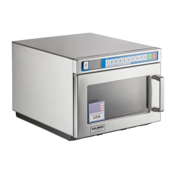
Summary of Contents for Solwave 180MWASHD12
- Page 1 Commercial Microwave SERVICE MANUAL Models 180MWASHD12 180MWASHD18 180MWASHD21 16400050...
-
Page 2: Table Of Contents
Table of Contents Safety Instructions......................... 3 Specifications ........................4 Installation ........................... 4 Owner’s Information ......................5-6 Components Location ...................... 7-11 Airflow ..........................12 Component Testing ....................... 13-14 Service Mode……………………………………………………………………………………….15 Performance Testing………………………………………………………………………………16 Wiring and Schematic Diagrams..................17-18... -
Page 3: Safety Instructions
Safety Information CAUTION To avoid risk of personal injury or property damage, observe the following safety instructions: General Use: 1. Do not use regular cooking thermometers in oven. Most cooking thermometers contain mercury and may cause an electrical arc, malfunction, or damage to oven. 2. -
Page 4: Specifications
All safety information must be followed W ARNING To avoid risk of electrical shock, personal injury, or death, disconnect power to oven and discharge capacitor before servicing, unless testing requires power. Models 180MWASHD12 180MWASHD18 180MWASHD21 Power Source Voltage AC 208/240... -
Page 5: Owner's Information
Owner’s Information (D) (E) (ii) ( iii) (iv) (v) (vi) OVEN CLEARANCES CONTROL PANEL FEATURES (A) USB Port (F) Secondary Function Keypads Allow at least 2” (5.1 cm) of clearance (B) Display To activate, press and hold corresponding around top of oven. Proper air (C) Number Keypads number keypad. - Page 6 Access and Modify User Options There are several options you can change to customize the operation of the oven for your business. Options are shown below. The factory setting is shown in bold type. Press and hold keypad number “4”/ USER OPTIONS. If prompted, enter the PIN Code and press START/OK keypad Press the START/OK keypad to scroll through pages of user options To access an individual user option, press the corresponding number keypad...
-
Page 7: Components Location
Components Location BLOWER, CAPACITOR, DIODE, INTERLOCK... - Page 8 DOOR...
- Page 9 CONTROL BOARD, MAGNETRONS, DUCTS, FUSE...
- Page 10 TRAY, CAVITY, ANTENNAS...
- Page 11 WRAPPER, ACCESS PANEL, LAMP...
-
Page 12: Airflow
Air Flow 1. AIR ENTERS THROUGH FRONT FILTER 2. AIR IS DRAWN INTO BLOWER 3. AIR PUSHED THROUGH MAGNETRONS 4. AIR PUSHED CAVITY AND EXITS THROUG CAVITY DUCTS... -
Page 13: Component Testing
Component Testing Illustration Component Testing Results Disconnect all wires from TCO. Measure resistance across terminals. Open at 104° C (219° F Cavity Thermal Fuse ......Thermal Cutouts Magnetron TCO ........Open at 138° C (280° F) and Closed at 82° C (180° F). Discharge Capacitors Infinite resistance should be measured in one direction and... - Page 14 Remove all wires from motor. Blower Motor Measure resistance COM to 208 Approx 23Ω Measure resistance COM to 230 Approx 26Ω Measure resistance 208 to 230 Approx 3Ω Remove all wires from motor. Stirrer Motor- 25RPM Measure coil resistance Approximately 25k Ω Discharge Capacitor Remove all wires from terminals, and Transformer...
-
Page 15: Service Mode
Service Mode TO ACCESS THE SERVICE MODE: PRESS AND HOLD THE “7” PAD UNTIL THE PIN PROMPT IS DISPLAYED • AT THE PIN PROMPT, ENTER 1,3,5,7 then 9 THEN SELECT FROM THE • FOLLOWING: o 1 – USAGE This shows Door Cycles, Tube Cycles, and Tube Hours. o 2 - ERROR HISTORY This shows any Error Codes that have occurred o 3 - PIN CODE... -
Page 16: Performance Testing
Performance Testing All SOLWAVE microwave oven power outputs are rated using the IEC705 standards. Using the IEC705 test method requires precision measurements and equipment that is not practical to be performed in the field. Using the test shown below will indicate if the oven performance is satisfactory. -
Page 17: Wiring And Schematic Diagrams
Wiring Diagrams & Schematics 180MWASHD12... - Page 18 180MWASHD18 & 180MWASHD21...


Need help?
Do you have a question about the 180MWASHD12 and is the answer not in the manual?
Questions and answers