Table of Contents
Advertisement
Quick Links
Advertisement
Table of Contents

Related Manuals for Solwave 180MWASS022


Summary of Contents for Solwave 180MWASS022
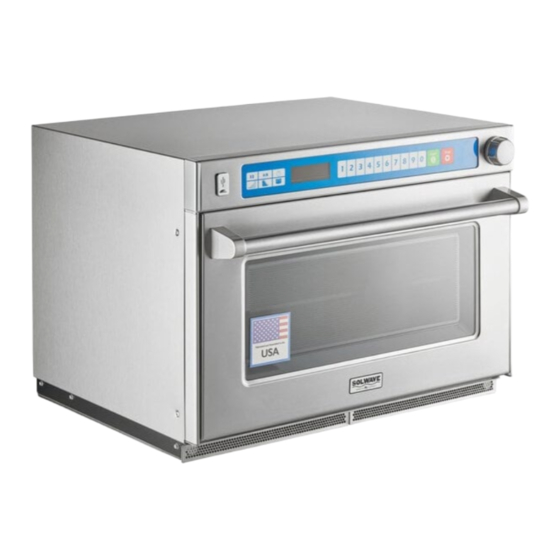
- Page 1 Commercial Microwave SERVICE MANUAL Models 180MWASS022 180MWASS035 16400051...
-
Page 2: Table Of Contents
Table of Contents IMPORTANT SAFETY INSTRUCTIONS ................3-5 Oven Specifications ......................4 Installation & Cleaning ......................5 Reference Guide........................ 6-7 User Options ......................... 8 Cooking Instructions ......................9 Component Location ...................... 10-15 Door & Door Switch Adjustment ..................16-17 Service Test Mode ......................18 Microwave Power Test ....................... - Page 3 PRECAUTIONS TO AVOID POSSIBLE EXPOSURE TO EXCESSIVE MICROWAVE ENERGY DO NOT attempt to operate this oven with the door open since open door operation can result in harmful exposure to microwave energy. It is important not to defeat or tamper with the safety interlocks.
- Page 4 ARNING To reduce the risk of burns, electrical shock, fire, or personal injury when using electrical equipment, basic safety precautions should be followed. READ AND FOLLOW the specific DO NOT use the cavity for storage. DO NOT leave paper products, cooking utensils, or food in the cavity when not in “PRECAUTIONS TO AVOID POSSIBLE use.
-
Page 5: Important Safety Instructions
CAUTION To avoid risk of personal injury or property damage, observe the following safety instructions: General Use: 11. Do not heat sealed containers or plastic bags in 1. Do not use regular cooking thermometers oven. Food or liquid could expand quickly and in oven. -
Page 6: Oven Specifications
All safety information must be followed W ARNING To avoid risk of electrical shock, personal injury, or death, disconnect power to oven and discharge capacitor before servicing, unless testing requires power. Models 180MWASS022 180MWASS035 Power Source Voltage AC 240/208 VAC... -
Page 7: Installation & Cleaning
INSTALLATION & CLEANING ARNING Unpacking Oven • Inspect oven for damage such as dents in door or inside oven cavity. • Report any dents or breakage to source of purchase immediately. Do not attempt to use oven if damaged. o avoid risk of electrical shock or •... -
Page 8: Reference Guide
QUICK START REFERENCE GUIDE... -
Page 10: User Options
USER OPTIONS... -
Page 11: Cooking Instructions
COOKING INSTRUCTIONS... -
Page 12: Component Location
Component Locations... -
Page 18: Door & Door Switch Adjustment
Door and Door Switch Adjustments Primary Switch The Primary Switch found top center of oven. Its purpose is to inform the control board that the door is either in the open or closed position. To Access: 1. Unplug the oven and remove the outer case. 2. - Page 19 Right Side The right side switches are protected by the F2 fuse and are part of the two bottom high voltage transformer circuits (T3 bottom right & T4 bottom left). If not adjusted properly the symptoms would be low heat (blown F2 fuse or incomplete circuit to the bottom transformers).
-
Page 20: Service Test Mode
Service Test Mode HIDDEN PAD MSO Units have an easily accessed Service Mode that allows a technician to operate components, clear service alarms, check door cycles, and check magnetron hours. To enter the Service Mode, perform the following: PRESS and RELEASE the Hidden Pad PRESS and RELEASE In Order: 1, 3, 5, 7, 9. -
Page 21: Microwave Power Test
Performance Testing Power Test All Solwave microwave oven power outputs are rated using the IEC705 standards. Using the IEC705 test method requires precision measurements and equipment that is not practical to be performed in the field. Using the test shown below will indicate if the oven performance is satisfactory. -
Page 22: Component Specifications
Component Testing Illustration Component Testing Results Disconnect all wires from motor Antenna Motor Measure resistance across terminals……... 12.2K Ω Remove fuse and check end-to-end 12 amp (qty 4)………………………………. Continuity 30 amp (qty 2)………………………………. Continuity Fuses HV Transformer Secondary 800ma (qty 4).. Continuity IF MAIN FUSE IS OPEN, THE FUSE AND MONITOR RELAY BOARD MUST BE... - Page 23 Disconnect wires to switch. With door open measure resistance Secondary Switch Terminal to Terminal…………………….. Open/Infinite.. With door closed measure resistance Terminal to Terminal…………………….. Closed/Continuity Measure resistance from: Approximately 6 to 7 MΩ (Diode in circuit) Note: If using a digital meter it Terminal 0 to Terminal 1 (coil) ....
- Page 24 Discharge Capacitors! Between Terminals: Less than 1 Ω. Remove wires from magnetron and Each terminal to ground measures connect ohmmeter to terminals. Also check Infinite resistance. between each terminal and ground. NOTE: This test is not conclusive. If oven does not heat and all other Magnetron (4) Magnetron 1 = Top Right components test good, replace the...
-
Page 25: Wiring And Schematic Diagrams
Schematics & Diagrams – 180MWASS022 & 180MWASS035...
Need help?
Do you have a question about the 180MWASS022 and is the answer not in the manual?
Questions and answers