
Subscribe to Our Youtube Channel
Related Manuals for Funke FSG80


Summary of Contents for Funke FSG80
- Page 1 FSG80 VHF Communication Transceiver for Ground Operation P/N FSG80-(xxx)-(xxx) Operation and Installation Dokument-Nr. 01.145.010.71e f.u.n.k.e. means – fabrication · utilities · network · know-how · engineering k.e.
- Page 3 FSG80 / P/N FSG80-(xxx)-(xxx) Operation and Installation Change History Revision Date Description of Change 1.00 25.01.2024 First Release for Head-SW 2.00 / NF-FW 2.00 List of Service Bulletins (SB) Service-Bulletins are to be inserted in the manual and to be recorded in...
-
Page 4: Table Of Contents
FSG80 / P/N FSG80-(xxx)-(xxx) Operation and Installation CONTENT GENERAL ............................4 ..............................4 YMBOLS ............................4 BBREVIATIONS ............................ 4 USTOMER UPPORT ........................5 QUIPMENT HARACTERISTICS OPERATION ............................6 ..........................6 VERVIEW OF ONTROLS ON/OFF - C .......................... 7 OMMISSIONING ..............................8 ISPLAY ............................. - Page 5 FSG80 / P/N FSG80-(xxx)-(xxx) Operation and Installation INSTALLATION ..........................33 ............................33 DVICE AND ........................33 ELECOMMUNICATION ............................ 33 COPE OF ELIVERY ....................33 NPACKING AND NSPECTING THE QUIPMENT ............................... 34 OUNTING .......................... 34 QUIPMENT ONNECTIONS 4.6.1 Microphone Connection ........................34 4.6.2...
-
Page 6: General
1 GENERAL This manual contains information about the physical, mechanical and electrical characteristics, as well as information about installation and operation of the VHF voice radio FSG80. 1.1 Symbols Advices whose non-observance can cause radiation damage to the human body or ignition of combustible materials. -
Page 7: Equipment Characteristics
• Wide range power supply 11 – 30 VDC • Configurable energy saving mode The FSG80 is only certified as ground radio. It has no certification for on-board usage in an aeroplane. For this the almost identical ATR833-II is available. -
Page 8: Operation
FSG80 / P/N FSG80-(xxx)-(xxx) Operation and Installation 2 OPERATION 2.1 Overview of Controls Position and naming of control elements: The control elements have following functionality: Switch On press button for appr. 0,5 s ON/OFF Swich Off press button for appr. 3 s... -
Page 9: On/Off - Commissioning
FSG80 / P/N FSG80-(xxx)-(xxx) Operation and Installation 1. Marking (underline) of value for adjustment; value changeable with FRQ or VOL/SEL → Enter and continue with Cursor Button ► CURSOR short press 2. Activates in MEM menu the entry of names 3. -
Page 10: Display
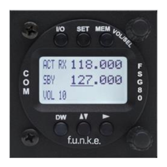
FSG80 / P/N FSG80-(xxx)-(xxx) Operation and Installation 2.3 Display The FSG80 shows the frequencies and the operating condition on a matrix LCD display with 128 x 64 pixels. Display Meaning Remark Fixed label for active frequency Label for standby frequency, when dual... -
Page 11: Frequency Setting
FSG80 / P/N FSG80-(xxx)-(xxx) Operation and Installation Display Meaning Remark If SEL was pressed, the Volume level for appropriate value of the VOL 03 receiving standard menu are displayed at (standard display) this position (see 2.5) Radio signal strength threshold required for reception;... -
Page 12: Automatic Selection 8.33 / 25 Khz Channel Bandwidth
FSG80 / P/N FSG80-(xxx)-(xxx) Operation and Installation 1. Entering a new standby frequency to the desired value, and then 2. Interchanging the new standby frequency and the previous active frequency by using the swap button . . Entering a new standby frequency can be done by... -
Page 13: Recall A Frequency From The User Memory
FSG80 / P/N FSG80-(xxx)-(xxx) Operation and Installation However, when choosing this option, please keep in mind to re-enable 8.33 kHz channel selection before flying into areas where 8.33 kHz channels are used. When having the channel selection configured for 8.33 kHz steps (see 0), the frequency is input in three steps: 118.910... -
Page 14: Recall A Frequency From The List Of The 10 Last Used
FSG80 / P/N FSG80-(xxx)-(xxx) Operation and Installation A push on the swap button replaces the Active Frequency, a press on the SET button the Standby Frequency with the selected list entry. If no input is done for 10 seconds, the device returns to the standard view, too. - Page 15 FSG80 / P/N FSG80-(xxx)-(xxx) Operation and Installation Step Display (example) 1. Tune in frequency: 118.275 Have frequency to be stored set 124.350 as standby frequency VOL 05 2. Enter memory list: 118.275 With a long press on MEM the 124.350...
-
Page 16: Atr Frequency Tool
2.4.6 ATR Frequency Tool The ATR Frequency Tool from Version 1.5 supports the FSG80. With the tool the frequency memory of the FSG80 can be managed, i.e. frequencies can be added, edited and deleted. The frequency list can be stored as a file. -
Page 17: Basic Settings
FSG80 / P/N FSG80-(xxx)-(xxx) Operation and Installation 2.5 Basic Settings To choose between the following settings, use the SET button: 1. VOL Volume (chosen by default) 2. SQL Squelch (noise suppression) 3. STL Volume Sidetone left 4. STR Volume Sidetone right 5. -
Page 18: St1 - Volume Sidetone Headset 1
FSG80 / P/N FSG80-(xxx)-(xxx) Operation and Installation 123.450 118.275 SQL 2 Range: 0 - 9 The setting for the squelch depends on different factors, like environmental noise. A lower number means higher input sensitivity. This allows reception of weaker signals (radio stations at higher distance), but can also result in pickup of radio interference sources (power supplies, engine, strobe lights). -
Page 19: Ext - Volume Of The External Audio Input
FSG80 / P/N FSG80-(xxx)-(xxx) Operation and Installation 118.275 ST2 4 Range: 0 – 20 2.5.5 EXT – Volume of the external Audio Input By shortly pressing the SET key four times, the volume of external audio signals (warning tones, music, etc. …) can be controlled with the rotary knob. -
Page 20: Con - Contrast
FSG80 / P/N FSG80-(xxx)-(xxx) Operation and Installation Range: 0 - 9 2.5.7 CON – Contrast By pressing the SET eight times the last configuration item is reached in the standard menu, where the contrast of the display can be adjusted with the VOL/SEL turn knob. -
Page 21: Reception
VOL 5 2.8 REPLAY Funktion The FSG80 automatically stores the last 9 seconds of an incoming radio call. Pressing the CURSOR key will play the last received radio message. The display will show » R E P L A Y » for the duration of the playback. -
Page 22: Dual Watch Operation
FSG80 / P/N FSG80-(xxx)-(xxx) Operation and Installation 2.9 DUAL WATCH Operation “dual watch” FSG80 comprises receiver; therefore (simultaneously monitoring two frequencies) is implemented by alternating automatically between the active and the standby frequency. With dual watch mode active, basically the standby frequency is tuned in, shortly interrupted in regular intervals by tuning in the active frequency for a fraction of a second. -
Page 23: Digital Outputs
2.10.2 Runway lightning When the FSG80 detects three times an opening and closing of the squelch within five seconds, the signal RUNWAY LIGHTNING (pin 7 at the device connector) is set to high for one second. This can be used for the activation of a runway lightning. -
Page 24: Configuration
FSG80 / P/N FSG80-(xxx)-(xxx) Operation and Installation 3 CONFIGURATION A very long press of SET (5 seconds) accesses the configuration menu. The configuration menu is used for fundamental settings. To choose between the following settings, use the SET button: 1. SPACING Channel spacing 2. -
Page 25: Spacing - Channel Spacing
FSG80 / P/N FSG80-(xxx)-(xxx) Operation and Installation 3.1 SPACING – Channel Spacing With this setting, the FSG8 can be configured to constrain frequency selection to 25 kHz channels only. This can be used to speed up the manual frequency input in areas where no 8.33 kHz channel spacing is used (see also chapters 2.4.1 and 2.4.2). -
Page 26: Ptt Select - Button Selection
FSG80 / P/N FSG80-(xxx)-(xxx) Operation and Installation ever on: no display darkening at all ACT RX 123.450 118.275 DISPLAY ever on off xxx s: automatic display darkening after xxx seconds after last user interaction (xxx= 10s, 20s, 30s, 60s, 120s) ACT RX 123.450... - Page 27 FSG80 / P/N FSG80-(xxx)-(xxx) Operation and Installation all mics: both PTT buttons and all microphones are used for transmissions, no matter what PTT button was pressed. ACT RX 123.450 118.275 PTT SLCT all mics one mic: according to the PTT button pressed, the associated...
-
Page 28: Duowatch - Dual-Watch Volume Reduction
FSG80 / P/N FSG80-(xxx)-(xxx) Operation and Installation 3.4 DUOWATCH – Dual-Watch Volume Reduction By shortly pressing the SET button four times, with help from the VOL/SEL rotary knob the lowering of the volume level (“mute”) for receptions on the standby frequency (when having dual watch active) can be controlled. This allows acoustic distinction between both frequencies. -
Page 29: Mic Type - Selection Microphone Type
FSG80 / P/N FSG80-(xxx)-(xxx) Operation and Installation 123.450 118.275 EXTAUDIO auto off not RXTX: The external audio input is automatically deactivated during radio receptions or transmit mode. This setting does not use the external audio activity sensing, and therefore can introduce noise when no signal source is connected. -
Page 30: Mic 1 / 2 - Microphone Input Sensitivity
FSG80 / P/N FSG80-(xxx)-(xxx) Operation and Installation microphones are deactivated via a switch, the standard microphone inputs are automatically activated. ACT RX 123.450 118.275 MIC1 TYPE auto Range: auto, standard, dynamic ACT RX 123.450 118.275 MIC2 TYPE standard Range: auto, standard, dynamic 3.7 MIC 1 / 2 –... -
Page 31: Spk Mode - Speaker Deactivation
FSG80 / P/N FSG80-(xxx)-(xxx) Operation and Installation ACT RX 123.450 118.275 MIC2 std sens: 4 Range 0 – 9 ACT RX 123.450 118.275 MIC2 dyn sens: 4 Range 0 – 9 3.8 SPK MODE – Speaker Deactivation The menu item SPK MODE determines whether the speaker is deactivated permanently. -
Page 32: Fw /Sw - Firmware / Software Version
FSG80 / P/N FSG80-(xxx)-(xxx) Operation and Installation When "on" is set, the radio will start as soon as the operating voltage is supplied to the unit. 123.450 118.275 AUTO ON If "off" is set, the device remains switched off when the voltage is applied, no matter how switched off. -
Page 33: Master Reset - Reset To Factory Settings
FSG80 / P/N FSG80-(xxx)-(xxx) Operation and Installation 3.11 Master Reset – Reset to Factory Settings With following procedure all configurations are reset to the factory settings. Switch of the device. Press MEM button and DW button and switch the unit on. Following screen appears after start-up:... -
Page 34: Overview Configuration Menu (Setup)
FSG80 / P/N FSG80-(xxx)-(xxx) Operation and Installation 3.12 Overview Configuration Menu (Setup) Dok.-Nr. 01.145.010.71e / Revision 1.00... -
Page 35: Installation
6k00A3E for 25khz channel spacing Emission Designator: 5k00A3E for 8,33kHz channel spacing 4.3 Scope of Delivery Part No. Description FSG80 – VHF communication transceiver FSG80 2 mounting screws and 2 hollow screws – ZUB4 for panels up to 3 mm. SSATR2... -
Page 36: Mounting
FSG80 / P/N FSG80-(xxx)-(xxx) Operation and Installation 4.5 Mounting • Suitable sets of cables are available from f.u.n.k.e. AVIONICS GmbH. • Select a position away from heat sources. Care for adequate convection cooling. • Leave sufficient space for the installation of cables and connectors. -
Page 37: Headset-Connection
FSG80 / P/N FSG80-(xxx)-(xxx) Operation and Installation 4.6.2 Headset-Connection Two headsets may be connected in parallel per input. In this case the total impedance shall not be less than 100 Ω. 4.6.3 Audio-Input The external audio input can be used for the input of warn tones or music etc. -
Page 38: Connector - Pin Allocation
FSG80 / P/N FSG80-(xxx)-(xxx) Operation and Installation 4.7.2 Connector – Pin Allocation D-SUB Connector 25 Pin Female seen from solder side Dok.-Nr. 01.145.010.71e / Revision 1.00... - Page 39 FSG80 / P/N FSG80-(xxx)-(xxx) Operation and Installation Names Functionality LSP(+) Output external Loudspeaker Positive HEADSET-1 (+) Output 1 Headset-Speaker Positive GND (HEADSET-1) Output 1 Headset-Speaker Negative EXT-NF Input external Audio-Signal MIC 2 DYN Input Microphone 2 Dynamic MIC 1 GND...
-
Page 40: Antenna
FSG80 / P/N FSG80-(xxx)-(xxx) Operation and Installation 4.8 Antenna 4.8.1 Antenna Selection • A VHF-COM-Antenna with an impedance of 50 Ohm is required. • Choose an antenna type feasible for the mounting location. • The antenna should be located far away from other VHF antennas. -
Page 41: Drawings
FSG80 / P/N FSG80-(xxx)-(xxx) Operation and Installation 4.10 Drawings 4.10.1 Dimensions Dok.-Nr. 01.145.010.71e / Revision 1.00... -
Page 42: Mounting Advices
FSG80 / P/N FSG80-(xxx)-(xxx) Operation and Installation 4.10.2 Mounting Advices For mounting in panel with a thickness of 3-5 mm longer screws are available (Order-No. ZUB5). Dimensions in Dimensions of connector area panel cut-out No screws may be turned in more than max. 15mm into the device –... -
Page 43: Appendices
FSG80 / P/N FSG80-(xxx)-(xxx) Operation and Installation 5 APPENDICES 5.1 Frequency/Channel-Plan In the following table examples for operating and displayed frequencies in the range between 118.000 ... 118.100 MHz are given. This table can be continued to 136.975 MHz following the same scheme. -
Page 44: Technical Summary
FSG80 / P/N FSG80-(xxx)-(xxx) Operation and Installation 5.2 Technical Summary 5.2.1 General Type: FSG80, P/N FSG80-(xxx)-(xxx) Frequency Range: 25 kHz spacing: 118.000 MHz to 136.975 MHz 8.33/25 kHz spacing: 118.000 MHz to 136.975 MHz Number of Channels: 25 kHz spacing: 760 channels 8.33/25 kHz spacing: 2.278 channels... -
Page 45: Receiver Characteristics (En300 676)
FSG80 / P/N FSG80-(xxx)-(xxx) Operation and Installation No.: 1-4786/01-22-05 MPE (EC) issued by CTC advanced GmbH EMC requirements EN 301 489-1 V2.2.3 EN 301 489-22 V2.1.1 CTC advanced GmbH Doc. No.: 1-4786/22-01-03 Radio spectrum EN 300-676-1 V1.5.2 EN 300-676-2 V2.1.1 (8.33 kHz CH spacing, ground operation) -
Page 46: Transmitter Characteristics (En300 676)
FSG80 / P/N FSG80-(xxx)-(xxx) Operation and Installation Cross modulation rejection 8.33kHz: 127.5MHz -1 MHz: 82.1 dB / +1MHz: 80.0 25 kHz: 127.5MHz -1 MHz: 81.0 dB / +1MHz: 80.0dB RX freq. (MHz) / AF@ - Receiver dynamic range AF@ -1dBm AF change... - Page 47 FSG80 / P/N FSG80-(xxx)-(xxx) Operation and Installation >30 MHz – 1 GHz ≤ 42.5 dBm ≤ 42.2 dBm B= 10 kHz (56.2 nW) (60.3 nW) >1 GHz – 4 GHz ≤ -57,1 dBm ≤ -57.1 dBm B= 10 kHz (1.9 nW) (1.9 nW)
-
Page 49: Eg Konformitätserklärung
FSG80 / P/N FSG80-(xxx)-(xxx) Operation and Installation EG KONFORMITÄTSERKLÄRUNG EG-Konformitätserklärung zur Richtlinie 2014/53/EU EG-Gebrauchstauglichkeitserklärung für Interoperabilitätskomponenten gemäß (EU) 2018/1139 EC-Declaration of Conformity to Directive 2014/53/EC EC-Declaration of Suitability for use of interoperability constituents according to (EU) 2018/1139 CE-Déclaration de conformité à la directive 2014/53/CE CE-Déclaration d'aptitude à... - Page 50 FSG80 / P/N FSG80-(xxx)-(xxx) Operation and Installation 2014/53/EG Funkanlagen-Richtlinie Wir erklären in alleiniger Verantwortung, dass die oben bezeichnete Produkte mit folgenden Europäischen 2014/53/EC Radio Equipment Directive Richtlinien und Verordnungen übereinstimmen: 2014/53/CE Directive RED (EU) 2018/1139 Verordnung Zivilluftfahrt (EU) 2018/1139 Regulation Civil Aviation...
- Page 51 FSG80 / P/N FSG80-(xxx)-(xxx) Operation and Installation Dok.-Nr. 01.145.010.71e / Revision 1.00...
- Page 52 FSG80 / P/N FSG80-(xxx)-(xxx) Operation and Installation Dok.-Nr. 01.145.010.71e / Revision 1.00...
-
Page 53: Disposal
FSG80 / P/N FSG80-(xxx)-(xxx) Operation and Installation DISPOSAL Umweltinformationen für Kunden innerhalb der Europäischen Union Regulatory and Compliance/WEEE Legislation within the European Union Gemäß der Europäischen Richtlinie 2002/96/EG über Elektro- und Elektronik-Altgeräte (WEEE) und die Änderung 2008/34/EG dürfen Produkte, die direkt am Gerät und/oder an der Verpackung mit diesem Symbol versehen sind, nicht zusammen mit gewöhnlichem Abfall entsorgt werden, sondern sind über... - Page 54 FSG80 / P/N FSG80-(xxx)-(xxx) Operation and Installation Notes: Dok.-Nr. 01.145.010.71e / Revision 1.00...
- Page 56 f.u.n.k.e. AVIONICS GmbH Heinz-Strachowitz-Str. 4 DE-86807 Buchloe Germany phone.: +49-8241 80066 0 fax.: +49-8241 80066 99 E-mail: service@funkeavionics.de www.funkeavionics.de f.u.n.k.e. means – fabrication · utilities · network · know-how · engineering k.e.
Need help?
Do you have a question about the FSG80 and is the answer not in the manual?
Questions and answers