
Related Manuals for Funke ATR833S


Summary of Contents for Funke ATR833S
- Page 1 ATR833S VHF Communication Transceiver P/N 833S-(Cxxx)-(Cxxx) Operation and Installation (Document-Nr. 01.142.010.71e) f.u.n.k.e. means – fabrication · utilities · network · know-how · engineering k.e.
- Page 3 ATR833S / P/N 833S-(Cxxx)-(Cxxx) Operation and Installation Change History Revision Date Change Description First release for 2-DS / 2x8 LCD HMI 1.00 27.01.2017 Firmware Rev1.0 Head Software Rev1.0 Chap. 2.4.6 Note on ATR frequency tool inserted / chap. 4.7.3.2 Note Garmin protocol 1.01...
-
Page 4: Table Of Contents
ATR833S / P/N 833S-(Cxxx)-(Cxxx) Operation and Installation Content GENERAL ............................... 5 ..............................5 YMBOLS ............................5 BBREVIATIONS ............................. 6 USTOMER ERVICE ..............................6 EATURES OPERATION ............................7 ..........................7 VERVIEW OF ONTROLS ON/OFF – C ........................8 OMMISSIONING ..............................9 ISPLAY .......................... - Page 5 ATR833S / P/N 833S-(Cxxx)-(Cxxx) Operation and Installation ......................... 37 QUIPMENT ONNECTIONS 4.6.1 Microphone Connection ......................37 4.6.2 Headset-Connection ........................37 4.6.3 Audio-Input ..........................37 4.6.4 Operation with Cable Adapter ....................38 ..............................38 IRING 4.7.1 Cable Cross Section ........................38 4.7.2...
-
Page 6: General
1 GENERAL This manual contains information about the physical, mechanical and electrical characteristics, as well as information about installation and operation of the aeronautical VHF voice radio ATR833S. 1.1 Symbols Advice, non-observance of which could cause radiation damage to the human body or ignition of combustible materials. -
Page 7: Customer Service
ATR833S / P/N 833S-(Cxxx)-(Cxxx) Operation and Installation 1.3 Customer Service In order to facilitate a rapid return of shipments in case of repairs, please follow the instructions of the input guide “Reshipment RMA” provided at the Service-Area within the f.u.n.k.e. AVIONICS GmbH web portal www.funkeavionics.com. -
Page 8: Operation
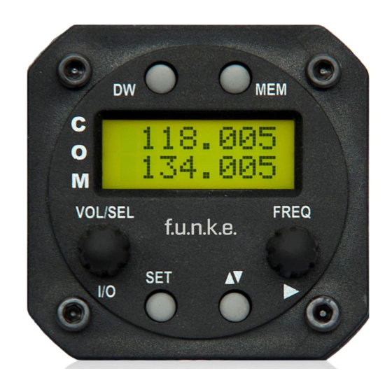
ATR833S / P/N 833S-(Cxxx)-(Cxxx) Operation and Installation 2 OPERATION 2.1 Overview of Controls Position and naming of control elements: The control elements have following functionality: Switch On press button for appr. 0,5 s ON/OFF Switch Off press button for appr. 2 s... -
Page 9: On/Off - Commissioning
ATR833S / P/N 833S-(Cxxx)-(Cxxx) Operation and Installation 1. Marking (underline) of value for adjustment; value changeable with FRQ or VOL/SEL Enter and continue with Cursor Button ► CURSOR short press 2. Activates the entry of names in MEM menu ... -
Page 10: Display
2.3 Display The ATR833S display shows the frequencies and the operating condition on a 2 line LCD each with 8 digits. The active frequency is shown in the upper line, the stand-by frequency in the lower line. - Page 11 ATR833S / P/N 833S-(Cxxx)-(Cxxx) Operation and Installation shows the successful storage > Memory stored of a frequency Transmission only with Very low supply voltage reduced power possible BATT (decreased radio range!) standard display when turning VOL 06 Volume level for receiving...
-
Page 12: Frequency Setting
ATR833S / P/N 833S-(Cxxx)-(Cxxx) Operation and Installation 2.4 Frequency Setting Frequency setting is always done by in two steps, as follows: 1. entering a new standby frequency to the desired value, and then 2. interchanging the new standby frequency and the previous active frequency by using the swap button . -
Page 13: Recall A Frequency From The User Memory
ATR833S / P/N 833S-(Cxxx)-(Cxxx) Operation and Installation In order to speed up the entering of new frequencies, it is possible to configure the radio to allow entering only those frequencies that are used with 25 kHz channel width. Please refer to chapter 3.1 for information on this configuration. -
Page 14: Recall A Frequency From The List Of The 10 Last Used
ATR833S / P/N 833S-(Cxxx)-(Cxxx) Operation and Installation Respectively A push on the swap button interchanges the newly set standby frequency and the former active frequency and leaves the memory list menu. If no input is done for 10 seconds the device returns to the standard view. -
Page 15: Editing Of The User-Defined Frequency List
ATR833S / P/N 833S-(Cxxx)-(Cxxx) Operation and Installation List entry „1“ contains the last standby frequency from the MEM menu If no input is done for 10 seconds, the device returns to the standard view. 2.4.5 Editing of the user-defined frequency list The standby frequency can be stored into any entry of the user memory. -
Page 16: Atr Frequency-Tool
2.4.6 ATR Frequency-Tool The ATR Frequency Tool supports the ATR833S from version 1.3. With the tool you can manage the frequency memory of the ATR833S, i.e. frequencies can be added, edited and deleted. The frequency list can be stored as a file. -
Page 17: Vol - Volume
ATR833S / P/N 833S-(Cxxx)-(Cxxx) Operation and Installation 3. VOX Voice Activated Intercom (speech level required to activate the intercom) 4. INT Volume Intercom 5. STL Volume Sidetone left 6. STR Volume Sidetone right 7. EXT Volume of external audio signals 8. -
Page 18: Vox - Voice Activated Intercom
ATR833S / P/N 833S-(Cxxx)-(Cxxx) Operation and Installation Range 0 - 9 The setting for the squelch depends on different factors. For motor aircraft an initial higher setting is typically appropriate, gliders may use a lower value. A lower number means higher input sensitivity. This allows... -
Page 19: Int - Intercom Volume
ATR833S / P/N 833S-(Cxxx)-(Cxxx) Operation and Installation In the case of very noisy backgrounds, or use of uncompensated microphones, the automatic VOX functionality may not work adequately. In these cases, it is possible to deactivate the VOX automatics with VOX: 0 = off, and to use an external intercom-switch instead. -
Page 20: Str - Volume Sidetone Right
ATR833S / P/N 833S-(Cxxx)-(Cxxx) Operation and Installation Range 0 – 20 2.5.6 STR – Volume Sidetone Right By briefly pressing the SET button five times you get access to the STR menu. Here the volume of the sidetone for the right seat can be adjusted. -
Page 21: Brt - Brightness
ATR833S / P/N 833S-(Cxxx)-(Cxxx) Operation and Installation 2.5.8 BRT – Brightness By pressing the SET seven times the brightness of the backlight of the LCD display can be switched on and off (or adjusted) with the VOL/SEL turn knob. Range 0 - 9 2.5.9 CON –... -
Page 22: Reception
ATR833S / P/N 833S-(Cxxx)-(Cxxx) Operation and Installation In order to re-enable transmission in this case, release PTT and push it again. When having more than one PTT button and microphones connected, the system can be configured (chapter 0) to use only one PTT button for transmissions. -
Page 23: Dual Watch Modus
ATR833S / P/N 833S-(Cxxx)-(Cxxx) Operation and Installation 2.8 Dual Watch Modus ATR833S comprises receiver; therefore DUAL-Watch (simultaneously monitoring two frequencies) is implemented by alternating automatically between the active and the standby frequency. With dual watch mode active, the standby frequency is tuned in, very briefly interrupted in regular intervals by the set auto-tuning to the active frequency for a fraction of a second. - Page 24 ATR833S / P/N 833S-(Cxxx)-(Cxxx) Operation and Installation Quick approach: Select or enter a standby frequency which is to be additionally monitored. Set SQL with the SET button and the rotary knob to a value of at least 01.
-
Page 25: Configuration
The selection of the values is done with the VOL/SEL turn knob. 3.1 CHANNEL SPACING With this setting, the ATR833S can be configured to limit frequency selection to 25 kHz channels only. This can be used to speed up the manual frequency input in areas where no 8.33 kHz channel spacing is... -
Page 26: Display - Energy Saving Mode (Automatic Display Darkening)
ATR833S / P/N 833S-(Cxxx)-(Cxxx) Operation and Installation 8.33 kHz: allows input of both 8.33 kHz and 25 kHz channels 25 kHz: allows input of 25 kHz channels only. A short press of SET switches to the next configuration item. Please remember to enable 8.33 kHz channel selection before flying into areas where 8.33 kHz channels are used. -
Page 27: Ptt Slct - Ptt Button Selection
ATR833S / P/N 833S-(Cxxx)-(Cxxx) Operation and Installation off xxx s: automatic display darkening after xxx seconds after last user interaction (xxx= 10s, 20s, 30s, 60s, 120s) Reactivation of the darkened display is done by pressing any key or turning any knob (the action of the key pressed is performed when pressing the key again after the display turned on) or when transmitting. - Page 28 ATR833S / P/N 833S-(Cxxx)-(Cxxx) Operation and Installation all mics: both PTT buttons and all microphones are used for transmissions, no matter what PTT button is pressed. one mic: according to the PTT button pressed, the associated microphone is activated left: only the left PTT button and the left microphone(s) are used for...
-
Page 29: Duowatch - Dual-Watch Volume Reduction
ATR833S / P/N 833S-(Cxxx)-(Cxxx) Operation and Installation When deactivating one PTT button and microphone for transmissions, e.g. in order to keep passengers from interfering with ATC communication, don’t forget to reactivate the co-pilot’s PTT at the end of the flight. - Page 30 ATR833S / P/N 833S-(Cxxx)-(Cxxx) Operation and Installation ever on: The external audio input is always on, even when in radio reception and transmit mode. Use this setting only for very high priority acoustic warnings, e.g. collision warning beep tones. auto off: The external audio input is automatically deactivated during transmit mode, or when no external audio activity is sensed.
-
Page 31: Mic L/R - Microphone Input Sensitivity
ATR833S / P/N 833S-(Cxxx)-(Cxxx) Operation and Installation 3.6 MIC L/R – Microphone Input Sensitivity Under the menu point “Microphone Input Sensitivity” you can adjust the gain of the microphone input and thus its sensitivity. The sensitivity can be adjusted with the VOL/SEL turn knob. The sensitivity can be adjusted separately for the left and right microphone. -
Page 32: Auto On - Power-On Behaviour
ATR833S / P/N 833S-(Cxxx)-(Cxxx) Operation and Installation A short press of SET switches to the next configuration item. 3.8 AUTO ON – Power-On Behaviour The last menu point AUTO ON configures the power-on behaviour of the radio With setting "on" the radio is switched on as soon as power is supplied to the unit. -
Page 33: Fw / Sw - Firmware / Software Version
ATR833S / P/N 833S-(Cxxx)-(Cxxx) Operation and Installation 3.9 FW / SW – Firmware / Software Version The firmware and software versions are shown under these menu items. The user cannot change these. Display Firmware-NF (Example) Display Software-Kopf (Example) Here a short press of SET terminates the configuration menu and the unit returns to the standard view. -
Page 34: Master Reset - Reset To Factory Settings
ATR833S / P/N 833S-(Cxxx)-(Cxxx) Operation and Installation 3.10 Master Reset - Reset to Factory Settings With the following procedure all configurations are reset to the factory settings. Switch off the device. Press MEM and DW button simultaneously and switch the unit on with these buttons pressed. -
Page 35: Overview Configuration Menu (Setup)
ATR833S / P/N 833S-(Cxxx)-(Cxxx) Operation and Installation 3.11 Overview Configuration Menu (Setup) Document-Nr.: 01.142.010.71e / Revision:1.05... -
Page 36: Installation
6k00A3E for 25khz channel spacing Emission Designator: 5k00A3E for 8,33kHz channel spacing 4.3 Scope of Delivery Part No. Description ATR833S – VHF communication transceiver ATR833S ZUB3 4x mounting screw M4x8 Fastening screw for panels with thickness up to 5 mm... -
Page 37: Unpacking And Inspection Of The Equipment
ATR833S / P/N 833S-(Cxxx)-(Cxxx) Operation and Installation EASA Form 1 4.4 Unpacking and Inspection of the Equipment Carefully unpack the equipment. Damage due to transportation must be reported to the shipping company immediately. Save the shipping container and all packing materials to substantiate your claim. -
Page 38: Equipment Connections
The (+UB)-wire (PWR – Pin 11/12) has to be protected by a circuit breaker (4 Amp. slow-blow)! 4.6.1 Microphone Connection The ATR833S automatically detects which type of microphone, dynamic or standard is connected to the unit. Standard microphones... -
Page 39: Operation With Cable Adapter
ATR833S / P/N 833S-(Cxxx)-(Cxxx) Operation and Installation Cable sets available from f.u.n.k.e. AVIONICS already have the external audio-input short-circuited with a blind plug. This blind plug can be easily removed in order to use the external audio input. If the external input is not used it needs to be short-circuited with GND, in order to avoid the pickup of electrical noise. -
Page 40: Connector - Pin Allocation
ATR833S / P/N 833S-(Cxxx)-(Cxxx) Operation and Installation 4.7.2 Connector – Pin Allocation The ATR833S has a 25 pole D-SUB connector. The pin allocation is given in the following diagram: D-SUB Connector 25 Pin Female seen from solder side Names Functionality... - Page 41 ATR833S / P/N 833S-(Cxxx)-(Cxxx) Operation and Installation Pin 8 is connected with Pin 19 for compatibility reason with ATR500 und ATR833S cable harnesses. DATA-RX RS232 Receive for Remote Control do not connect Pin 10 is used by adapters for device...
-
Page 42: Wiring With Cable Harness Bsks833X-S
View from 8: +5VDC aircraft’s side 5: GND shielding The remote interface of the ATR833S is a RX-TX-only connection with true RS232 voltage levels, with 9600 baud, 8 data bits, no parity, 1 stop bit, no handshake. Document-Nr.: 01.142.010.71e / Revision:1.05... -
Page 43: Antenna
ATR833S / P/N 833S-(Cxxx)-(Cxxx) Operation and Installation All messages start with the two byte sequence 0x02 (STX) and 0x72 (‘r’) for synchronization, followed by a message identification-byte and different numbers of data bytes. Byte # Value Description 0x02 (STX) Synchronization 0x72 (‘r’) -
Page 44: Installation Recommendation
ATR833S / P/N 833S-(Cxxx)-(Cxxx) Operation and Installation Choose an antenna type approved for the aircraft and the mounting location. The antenna should be located far away from ELT-antennas and other VHF antennas. Specified features depend on proper installation of the antenna. -
Page 45: Post-Installation Check
ATR833S / P/N 833S-(Cxxx)-(Cxxx) Operation and Installation If the VOX automatic is deactivated with VOX=0 then the intercom is activated using the intercom switch (not PTT), which connects PIN 7 (intercom) of the equipment connector to GND. For operation with VOX activated PIN 7 has to be connected to GND permanently. -
Page 46: Drawings
ATR833S / P/N 833S-(Cxxx)-(Cxxx) Operation and Installation 4.11 Drawings 4.11.1 Dimensions Document-Nr.: 01.142.010.71e / Revision:1.05... -
Page 47: Mounting Advice
ATR833S / P/N 833S-(Cxxx)-(Cxxx) Operation and Installation 4.11.2 Mounting Advice For mounting in panels with a thickness of up to 5 mm use the fastening screw M4x8 (ZUB3). Dimensions in Dimensions of connector area panel cut-out No screws may be turned in more than max. 10 mm into the device –... -
Page 48: Appendix
ATR833S / P/N 833S-(Cxxx)-(Cxxx) Operation and Installation 5 APPENDIX 5.1 Frequency/Channel-Plan In the following table examples for operating and displayed frequencies in the range between 118.000 ... 118.100 MHz are given. This table can be continued to 136.975 MHz following the same scheme. -
Page 49: Technical Data
ATR833S / P/N 833S-(Cxxx)-(Cxxx) Operation and Installation 5.2 Technical Data GENERAL COMPLIANCE ETSO-2C169a, ED23C Transceiver Class 4, 6 Receiver Class C, E, H1 & H2 ETSO 2C128 DIMENSIONS Height: 65 mm (2,56 in) Width: 65 mm (2,56 in) Depth: 163 mm (6,42 in) - Page 50 ATR833S / P/N 833S-(Cxxx)-(Cxxx) Operation and Installation FREQUENCY RANGE 118,000 MHz .. 136,975 MHz FREQUENCY STABILITY ±5 ppm at -20 °C .. + 55 °C COMPASS-SAFE DISTANCE 30 cm INTERCOM-INPUT Microphone inputs are connected to the intercom input. 100 mVRMS at the microphone input produce 0,5W output power at the headphone (300Ω).
-
Page 51: Environmental Conditions
ATR833S / P/N 833S-(Cxxx)-(Cxxx) Operation and Installation SELECTIVITY -40 dB- bandwidth < ±17.0 kHz (channel spacing 25 kHz) -60 dB- bandwidth < ±25.0 kHz SELECTIVITY -60 dB-bandwidth < ±7.37 kHz (channel spacing 8.33 kHz) ≥4 W an 4 Ω (Loudspeaker) NF-OUTPUT AF output deviation <... - Page 52 ATR833S / P/N 833S-(Cxxx)-(Cxxx) Operation and Installation Characteristic DO–160F Section Cat Condition ALTITUDE 4.6.1 C1 35 000 ft TEMPERATURE 2°C change rate minimum VARIATION per minute HUMIDITY 6 G operational shocks (11ms) SHOCK 20 G Crash Safety Test Type R in all 6...
- Page 53 ATR833S / P/N 833S-(Cxxx)-(Cxxx) Operation and Installation Characteristic DO–160F Section Cat Condition EMISSION OF RF 21.0 ENERGY LIGHTNING INDUCED X.. No ED23 test, TRANSIENT 22.0 not required SUSCEPTIBILITY LIGHTNING DIRECT 23.0 No test required EFFECTS ICING 24.0 No test required ELECTROSTATIC 25.0...
- Page 54 ATR833S / P/N 833S-(Cxxx)-(Cxxx) Operation and Installation Notices: Document-Nr.: 01.142.010.71e / Revision:1.05...
- Page 56 f.u.n.k.e. AVIONICS GmbH Heinz-Strachowitz-Str. 4 DE-86807 Buchloe Germany phone.: +49-8241 80066 0 fax.: +49-8241 80066 99 E-mail: service@funkeavionics.de www.funkeavionics.de f.u.n.k.e. means – fabrication · utilities · network · know-how · engineering k.e.
Need help?
Do you have a question about the ATR833S and is the answer not in the manual?
Questions and answers