Table of Contents
Advertisement
Quick Links
EC-TX823/821 Optical Fiber Expansion Module
EC-TX823/821 Optical Fiber Expansion Module
User Manual
Preface
Thank you for choosing INVT EC-TX823/821 optical fiber expansion modules.
EC-TX823/821 optical fiber expansion module is mainly used for the expansion of
functional modules. The EC-TX823 module includes three fiber optic interfaces, while the
EC-TX821 module includes one fiber optic interface. The modules need to be used with the
GD880 series VFD control box.
This manual describes the EC-TX823 module as an example. The EC-TX821 module only
has 2 fewer fiber optic interfaces than the EC-TX823 module and will not be introduced
separately.
This manual describes the product overview, installation, wiring, and commissioning
instructions. Before installing the VFD, read this manual carefully to ensure the proper
installation and running with the excellent performance and powerful functions into full
play.
Product features:
Directly installed on the expansion slot of the GD880 series VFD control box, powered
by the control box without the need for an external power supply
Used with the expansion extending board to enable slot expansion of the control box
Used with the IVDM-10 module to achieve AC line voltage detection for GD880 series
products such as active rectifier and regenerative rectifier
Used with the IVDM-20 module to detect the input and output voltage and current of
the system
Includes three/one fiber optic interface(s), supporting a 50MBd fiber optic
transmitting rate
1 Product overview
1.1 Model description
Figure 1-1 Product nameplate and model designation
Nameplate
XXXXXXXXXXXXXXX
Manufacture No.
EC-TX823
Product model
Product model EC - TX
823
Distinguishing code
821: indicates one optical-fiber communication
823: indicates three optical-fiber communication
Module category
TX: communication module
Product category
EC: expansion module
EC-TX823/821 Optical Fiber Expansion Module
1.2 Specifications
Table 1-1 Specifications
Parameters
Working temperature
-10–50ºC
Storage temperature
-20–60ºC
Relative humidity
5%–95% (No condensation)
Running environment
No corrosive gas
Installation method
Fixed with snap-fits and screws
Ingress protection (IP) rating
IP20
Heat dissipation method
Natural air cooling
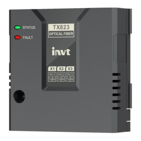
1.3 Structure
Figure 1-2 Structure diagram
1
2
7
3
4
5
6
Table 1-2 Component description
No.
Name
Description
STATUS
On: The power supply is normal.
1
indicator
Off: The power supply is abnormal.
FAULT
2
Standby
indicator
Installation
To fix the expansion module and maintain a good connection of
3
fixing hole
the PE layer
X1 fiber optic
4
Fiber optic communication port 1
terminal
X2 fiber optic
5
Fiber optic communication port 2
terminal
X3 fiber optic
6
Fiber optic communication port 3
terminal
Including the model and sequence number of the expansion
7
Nameplate
module
Connection
8
To connect the expansion module to the control box
port
Positioning
To align the expansion module and control box for easy
9
hole
installation
2 Installation and wiring
2.1 Installation precautions
Make sure the device have been powered off before installation.
There are 3 expansion module interfaces on the control box (expansion
slot 1, expansion slot 2, expansion slot 3). You can use expansion slot 2
Note
or expansion slot 3 according to the actual wiring.
It is recommended to install the fiber optic expansion module at
expansion slot 3.
Required tools: Phillips screwdriver PH1, straight screwdriver SL3
Table 2-1 Screw torque requirements
Screw size
M3
2.2 Dimensions
The size of the EC-TX823 optical fiber expansion module is 73.5×74×23.3mm (W*H*D), as
shown in Figure 2-1.
Specification
Figure 2-1 Product outline and mounting dimensions diagram (unit: mm)
8
2.3 Installation instructions
9
It is recommended to place the EC-TX823 fiber optic expansion module at expansion slot 3
of the control box. The following is an example of the installation at slot 3.
Step 1 Place the expansion module in the corresponding position of the control box
expansion slot 3, align it with the slot, and then buckle it together.
Step 2 Align the expansion module positioning hole with the positioning stud.
Step 3 Fix with a M3 screw. The installation is complete.
Expansion
slot 1
Expansion
slot 2
Expansion
slot 3
Note:
The expansion module and control box are electrically connected through slots.
Please install them in place.
To ensure the reliable operation of the expansion module and meet EMC requirements,
please tighten the screws according to the recommended torque for reliable
grounding.
2.4 Disassembly instructions
You can disassembly the module by reversing the order of steps described in section 2.3
Installation instructions.
Step 1
Disconnect the power supply and disassemble all cables connected to the
expansion module.
Step 2 Use a Phillips screwdriver to remove the grounding screw of the module.
Fastening torque
Step 3 Pull the module out to a suitable position.
0.55 N·m
2.5 User's wiring terminal
EC-TX823/821 Optical Fiber Expansion Module
72
X1
STATUS
LED1
FAULT
LED2
M3
8.25
Step 1
Step 2
Step 3
Figure 2-2 Terminal diagram
X1
X2
X3
VT1
VR1
VT2
VR2
VT3
VR3
X1
Advertisement
Table of Contents

Related Manuals for INVT EC-TX823


Summary of Contents for INVT EC-TX823
- Page 1 Figure 1-2 Structure diagram 8.25 2.3 Installation instructions It is recommended to place the EC-TX823 fiber optic expansion module at expansion slot 3 of the control box. The following is an example of the installation at slot 3. Preface Step 1 Place the expansion module in the corresponding position of the control box expansion slot 3, align it with the slot, and then buckle it together.
- Page 2 SLOT3 module The EC-TX823 module can be used to detect the AC line voltage detection for GD880 series products such as active rectifier and regenerative rectifier when used with the IVDM-10 module and to detect the input and output voltage and current of the system when used with the IVDM-20 module.
Need help?
Do you have a question about the EC-TX823 and is the answer not in the manual?
Questions and answers