Table of Contents
Advertisement
Quick Links
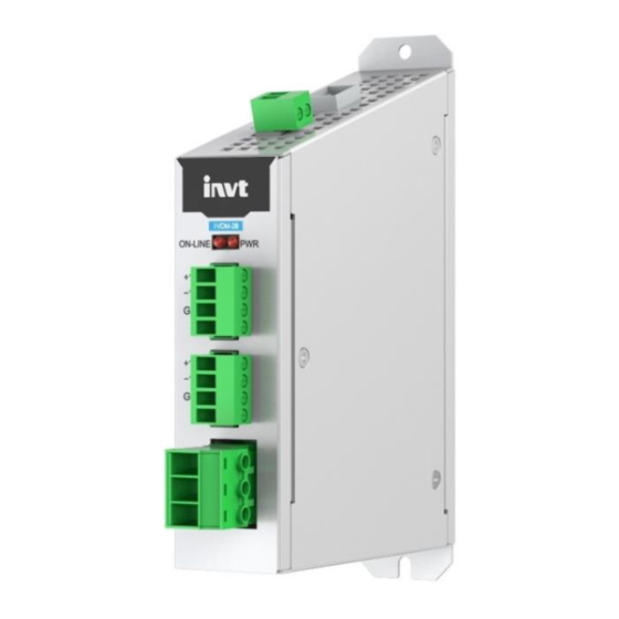
IVDM-20 DC Voltage Detection Module
IVDM-20 DC Voltage Detection Module
User Manual
Preface
Thank you for choosing INVT IVDM-20 DC voltage detection module.
IVDM-20 DC voltage detection module is mainly used in DC-DC bidirectional DC power
supply products to detect the input and output voltage and current of the system. It needs
to be used with the GD880 series VFD control box. The module transmits the detection
signal to the control box through optical fibers, achieving monitoring of system voltage
and current.
This manual describes the product overview, installation, wiring, and commissioning
instructions. Before installing the VFD, read this manual carefully to ensure the proper
installation and running with the excellent performance and powerful functions into full
play.
Product features:
Supports one DC voltage detection of 0–1000VDC
Supports two voltage type open-loop Hall current detection
Adopts optical-fiber communication, enabling fast and stable communication rate
Supports rear mounting method, facilitating dismounting and mounting
1 Product overview
1.1 Model description
Figure 1-1 Product nameplate and model designation
Nameplate
Product model
MODEL:
IVDM-20
INPUT:
DC24V 0.5A
Rated input
Manufacture No.
S/N:
XXXXXXXXXXXXXXX
IVDM - 20
Product model
10: AC voltage detection
20: DC voltage detection
IVDM: Synchronous voltage detection module
IVDM-20 DC Voltage Detection Module
1.2 Specifications
Table 1-1 Specifications
Parameters
Working temperature
-10–+50ºC
Storage temperature
-10–+60ºC
Relative humidity
5%–95% (No condensation)
Running environment
No corrosive gas
Installation method
Rear mounting method
IP rating
IP20
Heat dissipation method
Natural air cooling
1.3 Technical parameters
Table 1-2 Technical parameters
Parameters
Supply voltage/current
24V±5%/0.5A
Communication connection mode
Optical-fiber communication
Voltage detection
0–1000VDC
Current sampling
Two voltage type open-loop Hall current sensor
1.4 Structure
Figure 1-2 Structure diagram
X5
X4
X3
X2
X2
X1
Table 1-3 Component description
No.
Name
Description
X1-DC voltage
Input voltage range: 0–1000VDC
1
detection terminal
Cable cross-sectional area: 0.5–2.5mm
Current detection Hall component wiring terminal A
X2-Current detection
Cable cross-sectional area: 0.5–2.5mm
2
terminal A
Use shielded four-core twisted-pair cable with both ends
grounded. The total length of the cable is less than 1.5m.
Current detection Hall component wiring terminal B
X2-Current detection
Cable cross-sectional area: 0.5–2.5mm
3
terminal B
Use shielded four-core twisted-pair cable with both ends
grounded. The total length of the cable is less than 1.5m.
PWR power supply status indicator
Red LED ON: Power supply is connected.
Red LED OFF: The module is not powered on or the power
4
X3-Status indicator
supply is abnormal.
ONLINE operation status indicator
Red LED flashes: The communication is normal.
Red LED OFF: Operation exception.
Externally powered: 24VDC±5%/200mA
X4-24VDC power
5
Two-core twisted-pair cable is recommended.
input terminal
Cable cross-sectional area: 0.5–2.5mm
The expansion module communicates with the control box
X5-Optical fiber
6
through optical fiber.
connection terminal
Plastic optical fiber
2 Installation and wiring
Specification
2.1 Installation precautions
Make sure the device have been powered off before installation.
Note
Required tools: Phillips screwdriver PH1, straight screwdriver SL3
Specification
2.2 Dimensions
The dimensions of the DC voltage detection module is 37.4x113x180 mm (W*D*H), as
shown in Figure 2-1.
Figure 2-1 Product outline and mounting dimensions diagram (unit: mm)
PE
2.3 Installation instructions
The rear mounting method is used. Align the installation holes and tighten the screws.
2
2
2
Note:
Ensure that all terminals and fiber optic plugs are installed in place for effective
electrical connection.
2
The module is grounded through contact between its exposed metal shell and the
assembly board inside the cabinet, so the assembly board must be an exposed metal
plate. To ensure the reliable operation of the module and meet the EMC requirements,
please tighten the screws to ensure reliable grounding.
IVDM-20 DC Voltage Detection Module
Prevent the module from falling or shock to avoid damage.
Do not disassemble the module to avoid damage.
Please tighten the screws according to the required torque to avoid
damage or looseness.
Table 2-1 Screw torque requirements
Screw size
Fastening torque
M3
0.55 N·m
M4
1.2 N·m
ON-LINE
PRW
+15V
-15V
GND
1A
+15V
-15V
GND
1B
DC-
DC+
5
17.5
113
Figure 2-2 Installation diagram
Ø5
Ø5
Advertisement
Table of Contents

Related Manuals for INVT IVDM-20


Summary of Contents for INVT IVDM-20
- Page 1 +15V -15V Thank you for choosing INVT IVDM-20 DC voltage detection module. IVDM-20 DC voltage detection module is mainly used in DC-DC bidirectional DC power +15V -15V supply products to detect the input and output voltage and current of the system. It needs to be used with the GD880 series VFD control box.
- Page 2 Input voltage range: 0–1000VDC Voltage input- Start Note: The positive and negative DC voltage wiring on the IVDM-20 must match the positive and negative poles of DC-DC output wires. Check the electrical connection is Table 2-3 X2 terminal function definition proper.
Need help?
Do you have a question about the IVDM-20 and is the answer not in the manual?
Questions and answers