Advertisement
Quick Links
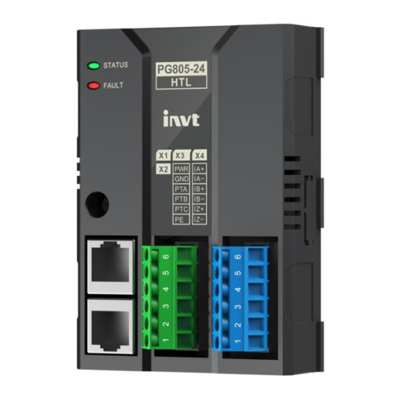
EC-PG805-24 HTL Incremental Encoder PG Expansion Module
EC-PG805-24 HTL Incremental Encoder PG
Expansion Module User Manual
Preface
Thank you for choosing INVT EC-PG805-24 HTL incremental encoder PG expansion
module.
The EC-PG805-24 HTL incremental encoder PG expansion module is used with the GD880
series VFD control box to detect the HTL incremental encoder. The expansion module
monitors the rotational speed of the motor by detecting the output signal of the encoder,
providing real-time speed feedback for precise speed control.
This manual describes the product overview, installation, wiring, and commissioning
instructions. Before installing the VFD, read through this manual carefully to ensure the
proper installation and running with the excellent performance and powerful functions
into full play.
Product features
Incremental encoder multi-channel signal detection: IA+, IA -, IB+, IB -, IZ+, IZ-
Provides power supply for encoders: 15V ± 5% or 24V ± 5%/150mA
Supports 3 input signal types: open collector, push-pull, differential
Supports pulse reference and frequency division output
With the encoder disconnection detection function, avoiding the expansion of system
fault impact
Able to detect the motor temperature through the KTY84/PT100 temperature sensor
signal
Adopts digital filtering technology to improve electromagnetic compatibility and
realize long-distance stable reception of encoder signals
1 Product overview
1.1 Model description
Figure 1-1 Product nameplate and model
Nameplate
Manufacture No.
XXXXXXXXXXXXXXX
EC-PG805-24
Product model
EC - PG
805 - 24 - KY
Product
model
Temperature sensor category
KY: KTY84 temperature sensor supported
PTH: PT100 temperature sensor supported
Working power
05: TTL, 5V
24: HTL, 15V/24V
Distinguishing code
805: incremental encoder
Module category
PG: PG expansion module
Product category
EC: expansion module
EC-PG805-24 HTL Incremental Encoder PG Expansion Module
1.2 Specifications
Table 1-1 Specifications
Parameters
Working temperature
-10–+50℃
Storage temperature
-20–60.0℃
Relative humidity
5%–95% (No condensation)
Running environment
No corrosive gas
Installation method
Fixed with snap-fits and screws
Ingress protection (IP) rating
IP20
Heat dissipation method
Natural air cooling
1.3 Technical parameters
Table 1-2 Technical parameters
Parameters
Output voltage/current
15V±5% or 24V±5%/150mA
Max. input signal frequency
300KHz
Encoder input signal type
Open collector, push-pull, differential
Pulse reference signal type
Differential
Pulse reference signal voltage
15V±5% or 24V±5%
Pulse reference max. signal
400kHz
frequency
Frequency-divided output type
Differential
Frequency-divided output signal
5V ± 5%
voltage
Frequency division coefficient
1:255
Max. frequency-divided output
400kHz
frequency
Temperature detection
Supporting KTY84 or PT100 temperature detection
Disconnection detection
Supporting push-pull and differential encoders
Note: Disconnection detection function is only supported when the motor is running.
1.4 Structure
Figure 1-2 Component diagram
1
2
8
3
11
4
5
6
7
Table 1-3 Component description
No.
Name
Description
On: The expansion module is connecting with the
control box.
STATUS
Blinking (On: 500ms; Off: 500ms): The expansion
1
Status indicator (green)
module is connected with the control box.
Off: The expansion module is disconnected from the
control box.
FAULT
On: Encoder is faulty.
2
Encoder signal indicator
Off: Encoder is normal.
(red)
To fix the expansion module and maintain a good
3
Installation fixing hole
connection of the PE layer.
X1 – frequency-divided
4
Frequency-divided output
output RJ45
5
X2 – Pulse reference RJ45 Pulse reference
X3 – Encoder power
6PIN pluggable green terminal for encoder power
6
selection terminal
output, KTY84 or PT100 signal input
X4 – Encoder signal input
6PIN pluggable blue terminal for HTL incremental
7
terminal
encoder differential signal input
Cut the knock-out hole. The switch inside is used to set
8
Knock-out hole
the voltage class (15V or 24V) of the power supply of
the encoder.
9
Connection port
For electrical connection with the control box.
To align the expansion module and control box for
10
Positioning hole
easy installation
Including the model and sequence number of the
11
Nameplate
expansion module
2 Installation and wiring
2.1 Installation precautions
Specification
Note
Required tools: Phillips screwdriver PH1, straight screwdriver SL3
Screw size
Specification
2.2 Dimensions
The dimensions of the PG expansion module is 73.5×103×34 mm (W*H*D).
Figure 2-1 Product outline and mounting dimensions diagram (unit: mm)
2.3 Installation instructions
It is recommended to place the PG expansion module at expansion slot 1 of the control
box. The following is an example of the installation at slot 1.
Step 1 Place the expansion module in the corresponding position of the control box
expansion slot 1, align it with the slot, and then buckle it together.
Step 2 Align the expansion module positioning hole with the positioning stud.
9
Step 3 Fix with a M3 screw. The installation is complete.
10
Expansion
slot 1
Expansion
slot 2
Expansion
slot 3
Note:
The expansion module and control box are electrically connected through slots. Please
install them in place.
To ensure the reliable operation of the expansion module and meet EMC requirements,
please tighten the screws according to the recommended torque for reliable grounding.
2.4 Disassembly instructions
You can disassembly the module by reversing the order of steps described in section 2.3
Installation instructions.
Step 1
Disconnect all power supplies and disassemble all cables connected to the
expansion module.
Step 2 Use a Phillips screwdriver PH1 to remove the grounding screws of the expansion
module.
Step 3 Lift the expansion module out of the control box positioning stud and pull it out to
a suitable position. Disassembly is complete.
EC-PG805-24 HTL Incremental Encoder PG Expansion Module
Make sure the device have been powered off before installation.
The PG expansion module is recommended to be placed on expansion
slot 1. If there is a second PG expansion module, it can be placed in other
interfaces (expansion slot 2, expansion slot 3).
Table 2-1 Screw torque requirements
Fastening torque
M3
0.55 N·m
73.5
23.3
8.25
22.5
STATUS
FAULT
M3
6
6
5
5
4
4
3
3
2
2
1
1
34
Step 1
Step 2
Step 3
Advertisement

Related Manuals for INVT EC-PG805-24


Summary of Contents for INVT EC-PG805-24
- Page 1 Supporting push-pull and differential encoders module. The EC-PG805-24 HTL incremental encoder PG expansion module is used with the GD880 Note: Disconnection detection function is only supported when the motor is running. series VFD control box to detect the HTL incremental encoder. The expansion module 1.4 Structure...
- Page 2 (like power cables) with a recommended interval of 30cm. For the encoder wiring outside the cabinet, avoid parallel wiring with the power cable The EC-PG805-24 PG expansion modules is configured with a pull-up resistor and can work and avoid forming a ring shape. If conditions permit, it is recommended to use a metal in combination with multiple types of incremental encoders through various external conduit for wiring.
Need help?
Do you have a question about the EC-PG805-24 and is the answer not in the manual?
Questions and answers