Table of Contents
Advertisement
Advertisement
Table of Contents

Subscribe to Our Youtube Channel
Related Manuals for BougeRV Sunflow 60A


Summary of Contents for BougeRV Sunflow 60A
- Page 1 NEGATIVE GROUND MPPT SOLAR CHARGE CONTROLLER www.bougerv.com...
-
Page 3: Table Of Contents
Content 1. Safety Instructions -----------------------------------------------------------1 2. Technical After Services----------------------------------------------------2 3. Identification Of Parts-----------------------------------------------------3 4. LCD Display Interface Overview------------------------------------------4 5. System Wiring----------------------------------------------------------------5 6. Wiring Instructions--------------------------------------------------------- 5 7. LCD Display Interface-------------------------------------------------------7 7-1. Menu Display Icon------------------------------------------------------------7 7-2. Key Operation-----------------------------------------------------------------7 8. Working Mode----------------------------------------------------------------9 8-1. Working Mode 1: Load mode-----------------------------------------------9 8-2. - Page 4 Menu 10: Load mode(mode 1)------------------------------------------------19 Menu 10.1: Light control mode + Duration mode(mode 1)--------------20 Menu 11: Lithium battery low temperature charging protection (mode 1, mode 2)--------------------------------------------------------------------------20 Menu 12: Load short circuit protection(mode 1)---------------------------21 Menu 13: Charging current(mode 1, mode 2)------------------------------21 Menu 14: Constant voltage output of lead acid battery(mode 1, mode 2)------------------------------------------------------------------------------------21 Menu 15: Light control voltage(mode 1)-----------------------------------22...
-
Page 5: Safety Instructions
1. Safety Instructions Please follow the safety instructions for operation, the damage caused by not following the safety instructions shall be borne by the individual. Please save these instructions 1-1.General Safety Information 1.Read all of the instructions and cautions in the manual before installation. -
Page 6: Technical After Services
1-669-232-7427 Whataspp If you could provide the following relevant information to our email (service@bougerv.com); we can provide you with technical support solutions faster. (1)The connection method of the solar panels (series/parallel, quantity, voltage, power). (2)The voltage and battery type of the battery. -
Page 7: Identification Of Parts
3. Identification Of Parts 4 5 6 7 8 9 10 LCD Display Screen Button PV Positive Terminal PV Negative Terminal Battery Negative Terminal Load Negative Terminal Battery Positive Terminal Load Positive Terminal TTL Communication Interface Temperature sensor Interface RS485/CAN Communication Interface... -
Page 8: Lcd Display Interface Overview
4. LCD Display Interface Overview Daytime icon Bluetooth icon Night icon Battery type Solar panel Charging stage Battery Load light control icon Load Parameter Charging state Unit symbol Discharging state Operating mode System voltage Warning icon RS485/CAN communication icon... -
Page 9: System Wiring
5.System Wiring 1. The positive and negative poles of the battery must be connected to the battery terminals of the controller first. 2. Finally, connect the positive and negative poles of the solar panel to the PV terminals of the controller. 3.Make sure that the Bluetooth of the mobile phone is turned on, and open the APP "Solar"... - Page 10 3. Plug the cable into the 4. Tighten the screws. correct port. (Clockwise) 5. Check the wiring condition and put the plastic cover back. Please strictly follow the above sequence for connection. Note: During the wiring process, the attached terminal lugs can be used for connection.
-
Page 11: Lcd Display Interface
7. LCD Display Interface 7-1.Menu Display Icon Display Section Status Charge And Load Status Parameter BAT Type Indicate And Warning Description Status Icon Indication Status Daylight Detected Day Night And Charge No Daylight Detected Indication Solar Charging Battery Battery Voltage is Hight Battery Battery Voltage is Middle Indication... - Page 12 2. Enter the Parameter Setting Interface In the menu interface, press and hold the button for 2s to enter the menu parameter adjustment interface. 3. Adjust Parameters Enter the parameter setting interface, press the button to adjust the parameter.(Decrease) Enter the parameter setting interface, click the button to adjust the parameter.(Add) 4.
-
Page 13: Working Mode
8. Working Mode 8-1 Working Mode 1: Load mode Menu 1: Menu 2: Battery type setting System voltage Charging Stage Menu Menu 2.1: Boost charging voltage Menu 3: Menu 4: Solar panel output voltage Solar panel output current Menu 2.2: Floating charging voltage Menu 5: Menu 6:... -
Page 14: Working Mode 2: No Load Mode
Menu 15: Menu 14: Constant voltage Light control voltage output of lead acid battery Menu 17: Menu 16: Error code Light control delay 8-2 Working Mode 2: No load mode Menu 1: Menu 2: Menu 3: Battery type setting System voltage Solar panel output voltage Menu 4: Menu 5:... -
Page 15: Working Mode 3: Viewing Mode
Menu 2.2: Menu 2.1: Floating charging voltage Boost charging voltage Menu 2: System voltage Menu 2.3: Menu 2.4: Boost charging Equalizing charging reconnect voltage voltage 8-3 Working Mode 3: Viewing mode It is recommended to switch to mode 3 after setting the system parameters, so that it is convenient to check the daily work of the PV system. -
Page 16: Bluetooth Module
9. Bluetooth module Built-in Bluetooth communication function can monitor the operation data, fault status and adjust the operation parameters of the controller in real time through mobile APP. Download Scan the QR code to download the application; Solar APP IOS & Android Search for "Solar App"... -
Page 17: Parameter Setting Menu
10. Parameter setting menu Main Menu Automatic loop playback every 5s Main menu (current) Main menu (voltage) 1.On the parameter setting interface, if there is no operation for 10s, it will automatically jump back to the main menu. 2.On the parameter setting interface, if the parameter is not confirmed, the parameter will keep flashing, confirm until the parameter does not flash, indicating that the parameter setting is successful. -
Page 18: Menu 2: System Voltage(Mode 1, Mode 2)
Menu 2: System voltage(Mode 1, Mode 2) 1. Automatically identify voltage (only applicable to the lead-acid battery) 2. 12V 3. 24V Setting method: 1. On the system voltage menu, press and hold [SELECT] for more than 2s until the parameter flashes to enter the system voltage parameter setting interface. -
Page 19: Menu 2.2: Floating Charging Voltage(Mode 1,Mode 2)
Menu 2.2: Floating charging voltage(Mode 1, Mode 2) ①12V system: 9-17V, 0.1V step (default 13.8V) ②24V system: 18-34V, 0.2V step (default 27.6V) Note: This menu will only appear when the battery type is set to USE. Setting method: Same as above. Menu 2.3: Boost charging reconnect voltage (Mode 1, Mode 2) ①12V system:... -
Page 20: Menu 2.6: Over-Discharge Delay(Mode 1)
Menu 2.6: Over-discharge delay(Mode 1) 1-60s. (default 5s) Note: This menu will only appear when the battery type is set to USE. Setting method: Same as above. Menu 2.7: Over-discharge reconnect voltage(Mode 1) ①12V system: 9-17V, 0.1V step (default 12.6V) ②24V system: 18-34V, 0.2V step (default 25.2V) Note:... -
Page 21: Menu 4: Solar Panel Output Current(Mode 1,Mode 2,Mode 3)
Menu 4: Solar panel output current (Mode 1,Mode 2,Mode 3) Display solar panel output current. Note: The current value only can be read, but cannot be adjusted; Setting method: Same as above. Menu 5: Generated energy of the day (Mode 1, Mode 2, Mode 3) Display generated energy of the day. -
Page 22: Menu 7: Discharge Energy Of The Day(Mode 1, Mode 3)
Menu 7: Discharge energy of the day(mode 1, mode 3) Display the output energy of the controller load port of the day. Note: The value only can be read, but cannot be adjusted; Setting method: Same as above. Menu 8: The controller temperature (mode 1, mode 2,mode 3) Display the controller temperature. -
Page 23: Menu 10: Load Mode(Mode 1)
Menu 10: Load mode(mode 1) Setting method: Same as above. LCD screen Load mode Description number Normal The load is always on. on mode On the main menu interface, press and hold [ENTER] for more Manual mode than 2s to turn on/off the load. (not affected by light control) When there is no sunlight, the solar panel voltage is less than... -
Page 24: Menu 10.1: Light Control Mode + Duration Mode(Mode 1)
LCD screen Load Description number mode When there is no sunlight, the solar panel voltage is less than Pure light the light control on voltage, the control,turn on controller delays for 1 minute the load at night display: 11, and then turns on the load ; setting is and turn off the When there is sunlight, the solar... -
Page 25: Menu 12: Load Short Circuit Protection(Mode 1)
Menu 12: Load short circuit protection(mode 1) ①on: open load short-circuit protection (default ) ②oFF: close load short-circuit protection Setting method: Same as above. Menu 13: Charging current (mode 1, mode 2) Adjust current range: 0——rated current (for example:the 60A controller, adjusting current range is 0-60A)... -
Page 26: Menu 15: Light Control Voltage(Mode 1)
Menu 15: Light control voltage(mode 1) ①12V system voltage: 5-11V, 5V(default) ②24V system voltage: 10-22V, 10V(default) Note: ①Light control on: The solar panel voltage is less than the adjusting voltage. ② If it is the system of 24V, relevant voltage points shall be automatically multiplied by 2. -
Page 27: System Restart & Factory Reset
11. System restart & Factory reset Menu 18: System restart(mode 1, mode 2, mode 3) On the main menu, press and hold [ENTER] for more than 5s until the parameter flashes to enter the parameter setting interface. 2. On the parameter setting interface, single press [SELECT] or [ENTER] to choose F01 or F02. -
Page 28: Error Code
12. Error Code Error code Cause of failure Solution Normal system 1.Turn off load output, after the battery voltage recover to the over -discharge Battery reconnect voltage, relieve over-discharge to restore load output. over-discharge 2.The battery voltage does not match the system, check the system voltage. - Page 29 Error code Cause of failure Solution Battery high Charging will be stopped when temperature the battery temperature is above 75°C charging and resumed when it is below 70°C. protection Stop charging when the output voltage of the solar panel is higher Solar panel than 95V, and recover charging when over-voltage...
-
Page 30: Base Specification
13. Base Specification Model BJ2430N BJ2440N BJ2460N 12V/24V System voltage Rated charging current Battery Type SLD/GEL/FLD/LI/USE,SLD as default Maximum input 450W/12V 900W/12V 600W/12V of PV system 900W/24V 1800W/24V 1200W/24V Maximum PV 100V (95V protection, 90V recovery) input voltage MPPT operating (Battery voltage +2V)~72V voltage range MPPT tracking... - Page 31 Battery operating 8V-32V voltage range Baud rate: 9,600 bps communication RS485 RJ45 interface, with power output 5V/200 mA,The communication baud rate is 9,600 bps by default, adjustable. Bluetooth built-in bluetooth communication RJ45 interface, optional (RV-C protocol) communication Save the last 200 days of historical data Historical data PV overvoltage protection, PV reverse connection protection, PV short circuit protection, night...
-
Page 32: Battery Charge Parameter
14. Battery Charge Parameter Battery parameters Battery Type Sealed Lithium Custom Flooded lead Gel lead-acid Lead-Acid battery battery battery -acid battery Setting/ Voltage Overvoltage 16.0V 16.0V 16.0V 16.0V 16.0V ① disconnect voltage 0-17V (Default 14.6V) Note: Set to 0, (Do not ①... -
Page 33: Ttl Communication
15. TTL communication 1) Default baud rate: 9,600 bps; check bit: none; data bit: 8 bit; stop bit: 1 bit 2) Communication power supply output specification: (8.5V±1V)/: 100mA Definition VCC: communication power ① supply output ② RX: controller data receiving end ③... -
Page 34: Charging
18. Charging 18-1: Charging of lead-acid battery Charging voltage Constant voltage Floating charging MPPT Equalizing charging voltage charging Boost charging voltage Floating charging voltage Charging reconnect voltage Time Time Fig. 18-1 Charging curve of lead acid battery Select such battery types as SLD/FLD/GEL/USE, and select the appropriate system voltage. -
Page 35: Charging Of Lithium Battery
3) Excessive charging and excessive gas evolution may damage the battery plate and cause the active substances on the battery plate to fall off.Besides, excessive high equalizing charging voltage or excessive long equalizing charging duration may damage the battery. Please set relevant parameters according to the specifica- tions of the battery used in the system. -
Page 36: Product Dimensions
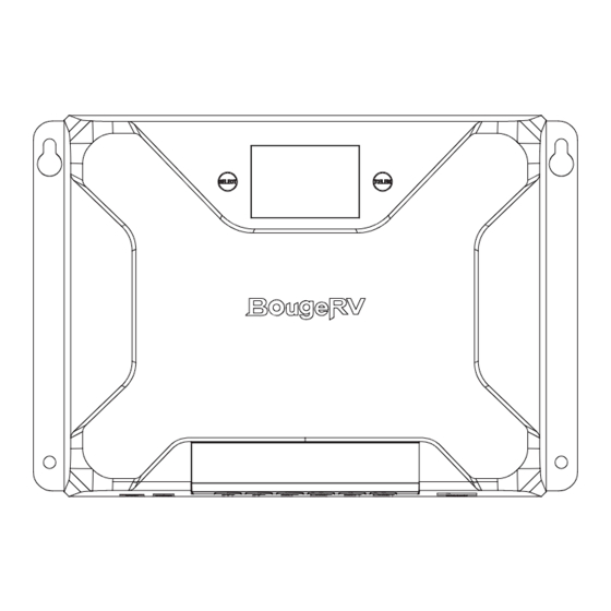
19. Product Dimensions 185mm BJ2430N 172mm φ5mm Model: BJ2430N Product dimension: 185*133*75mm Fixed hole position: φ5mm 227mm BJ2440N 214mm φ5mm Model: BJ2440N Product dimension: 227*159.6*75mm Fixed hole position: φ5mm... - Page 37 263mm 248mm BJ2460N φ5mm Model: BJ2460N Product dimension: 263*186*85mm Fixed hole position: φ5mm...
- Page 40 Make the journey service@bougerv.com 1-408-656-8402 www.bougerv.com 1-669-232-7427 Whataspp...
Need help?
Do you have a question about the Sunflow 60A and is the answer not in the manual?
Questions and answers