Table of Contents
Advertisement
Quick Links
ALYSEUM - SELECTOR & HOLD - User's manual 2.0
1.
Introduction
HOLD
S&H
TRIG
1
T&H
GATE
CV IN
RESET
OUT 1
T/G 1
N.C.
OUT 2
T/G 2
OUT 3
T/G 3
OUT 4
T/G 4
OUT 5
T/G 5
OUT 6
T/G 6
OUT 7
T/G 7
OUT 8
T/G 8
ALYSEUM
These modules can be controlled in 8 different modes of wich 5 exclusive:
1. Standalone by buttons.
2. Slave of the MATRIX II module linked to its preset and bank management.
3. CV Input with its bipolar offset setting.
4. MIDI NOTE or MIDI CC input.
5. Sequential switcher with a MIDI CLK input.
6. Sequential Switcher with a CLK/Trigger input.
7. Sequential Switcher with a CLK/Trigger + RST inputs.
8. CV & CLK/Trigger Inputs, like S&H
Two unique features increase the power of the different modes and their usabilities:
●
An "Arpeggiator-like" function is available for the Modes 5, 6 and 7 and including 4 patterns.
●
A "Steps Window" function is available for the Modes 3 until 8 and allows you to freely choose a range of steps in
number and location on the fly.
SELECTOR & HOLD – User's manual © - Revision 2.0 (Firmware 1.1) - Page 1
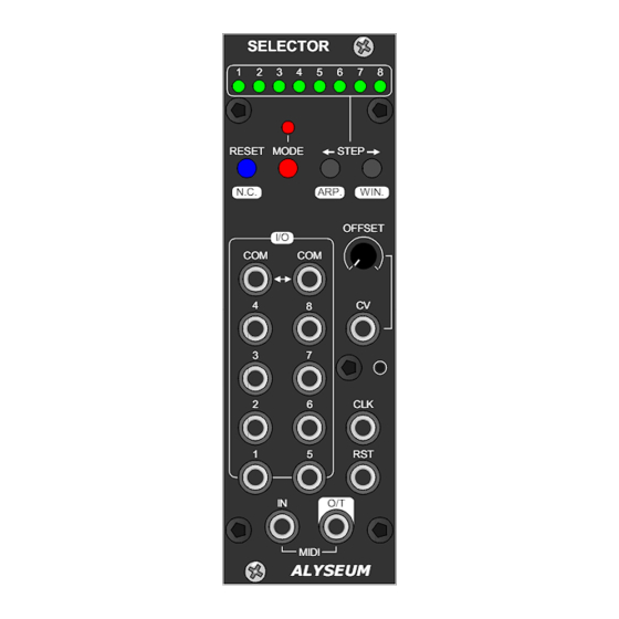
SELECTOR
2
3
4
5
6
7
8
MODE
STEP
ARP.
WIN.
OFFSET
I/O
COM
COM
4
CV
8
3
7
2
6
CLK
1
5
RST
IN
O/T
MIDI
ALYSEUM
The SELECTOR module is a highly versatile module in terms of
connectivity, control, extension and use.
Its front panel, combined with a multitude of control signals,
sets it apart from other sequencer switchers.
The heart of the module is a high Voltage and high quality
bi-directional addressed Selector 8↔1, also called Sequencial
switcher 8 ↔ 1 or Mul6plexer 8 → 1 or Demul6plexer 1 → 8.
Up to 8 SELECTOR modules can be chained to create a bigger
Selector up to 64 ↔ 1.
In every cases, only one Switcher is active at a time!
The HOLD module is an optional SELECTOR module's
companion which adds the features to it:
●
8 digital addressed outputs, selectable between Trigger
or Gate.
●
1 CV input to 8 analog addressed outputs, selectable
between S&H or T&H.
The 8 digital and 8 analogue outputs are synchronized with the
SELECTOR I/O.
Modes, features and chaining of the SELECTOR module are fully
preserved when the HOLD module is added!
(Firmware 1.1)
Advertisement
Table of Contents

Subscribe to Our Youtube Channel
Related Manuals for Alyseum SELECTOR


Summary of Contents for Alyseum SELECTOR
- Page 1 A "Steps Window" function is available for the Modes 3 until 8 and allows you to freely choose a range of steps in number and location on the fly. SELECTOR & HOLD – User’s manual © - Revision 2.0 (Firmware 1.1) - Page 1...
-
Page 2: Specifications
For order to use the chaining feature, install the module #1 on the left first and then the module #2 on the right and so on. Thus you visually respected the LED chaining! When install both SELECTOR & HOLD in chain, place always per pairs HOLD-SELECTOR + HOLD-SELECTOR + ..Procedure: Only connect the module to a Eurorack bus board powered by a specified A-100 power supply. - Page 3 SELECTOR modules must be powered by the same power supply, or generally powered ON/OFF simultaneously with the MATRIX II. ● The MIDI Out of the MATRIX II module must be connected to the MIDI Input of the SELECTOR module. ● Please refer to the user manual of the MATRIX II for more informations.
- Page 4 2. Use the COMs as Input, if you want to route signal to 1 of the 8 outputs - see figure 2. Figure: 1 Figure: 2 SELECTOR & HOLD – User’s manual © - Revision 2.0 (Firmware 1.1) - Page 4...
-
Page 5: Good To Know
MIDI - with the MATRIX II To guarantee the management of the Banks and Presets of the SELECTOR, it is important to wire the MIDI as shown below. The principe is simple, MATRIX II is the master, SELECTOR is slaves. - Page 6 The change between the two switches which are each in a different slave modules. Software countermeasures are taken to simulate the DG408 in the cases 2 and 3. SELECTOR & HOLD – User’s manual © - Revision 2.0 (Firmware 1.1) - Page 6...
-
Page 7: How To Use
NB: It is important that all modules in the chain are installed, powered and that MIDI is wired in loop! NB: Do not forget to remove the last MIDI cable from the loop after programming the addresses. SELECTOR & HOLD – User’s manual © - Revision 2.0 (Firmware 1.1) - Page 7... -
Page 8: Mode Selection
● With 2 modules in chaining, existing 16 steps and a seventeenth state when all the LEDs are OFF for No Connection (N.C.) ● ..SELECTOR & HOLD – User’s manual © - Revision 2.0 (Firmware 1.1) - Page 8... - Page 9 MATRIX II. ● A SAVE operation, saves the settings of the SELECTOR + Link to the Bank & Preset number displayed by the MATRIX During SAVE & LOAD operations, green & red LED blink one time. NB 1: The current Preset # is saved or loaded and displayed via the front panel of the MATRIX II, but the values are saved in the EEPROM of the SELECTOR (Master) module.
- Page 10 ● Afterwards: The first MIDI Note On or the first MIDI CC detected by the SELECTOR is saved (MIDI Channel sensitive). The 8 green LED flash 2 times to confirm. OR - Press shortly the button RESET to cancel the current programming.
- Page 11 NB 1: As soon as two LEDs are contiguous, you can continue to move starting and ending points together. NB 2: Modes 3 until 8 each have their Steps Window saved in EEPROM. SELECTOR & HOLD – User’s manual © - Revision 2.0 (Firmware 1.1) - Page 11...
-
Page 12: Firmware Upgrade
Press and hold the BOOT button, while turning the Eurorack case power back ON. The BOOT button is located behind the small hole in SELECTOR front panel, down the CV input and can be pressed using a thin, long object like, for example, a toothpick. -
Page 13: Warranty And Repair
This warranty does not apply to any products which have been repaired or altered by other than ALYSEUM, or which have been subject to ESD, moisture, abuse, accident, improper installation or use.
Need help?
Do you have a question about the SELECTOR and is the answer not in the manual?
Questions and answers