Table of Contents
Advertisement
Quick Links
Advertisement
Table of Contents
Troubleshooting

Related Manuals for Hardy HI6800 Series


Summary of Contents for Hardy HI6800 Series
- Page 1 HI6800 Series Application Controller User Guide...
-
Page 2: Corporate Headquarters
Hardy Process Solutions, Inc. Notice of Liability Information provided in this manual is intended to be accurate and reliable. However, Hardy Process Solutions, Inc. assumes no responsibility for its use, nor for any infringement of rights of third parties which may result from its use. -
Page 3: Table Of Contents
3.1.4 Warning and Safety Labels ............... 24 3.1.5 Operating Guidelines ................24 3.1.6 Electrostatic Discharge................25 3.1.6.1 Sources of Electrical Interference ............. 25 3.1.6.2 Emergency Power Control ..............26 3.1.7 Pre-installation Planning................26 3.1.8 Seismic Considerations ................27 Hardy H6800 Series Application Controllers User Guide... - Page 4 3.5.4 PROFINET Card ..................51 4 Commissioning ....................52 4.1 Connections ....................... 53 4.2 Powering on the HI6800 Series Application Controller ........54 4.2.1 DC Input Power ..................54 4.2.2 AC Input Power (Optional) ................ 54 5 Configuration ...................... 55 5.1 Accessing Configuration Parameters ..............
- Page 5 7.4.9 K: Load Sharing and Load Sensor Checkout ..........99 7.4.10 M: (*******) or (- - - - - - -) Error .............. 100 7.4.11 N: Application Controller Front Panel Display is Blank ......101 Hardy H6800 Series Application Controllers User Guide...
- Page 6 B.10 Programmers Quick Reference Guide ............113 B.11 I/I Diagrams and Drawings ................113 APPENDIX C - Installing Option Cards (Model HI6850)……………………..… 114 APPENDIX D - Glossary ..................115 Index ........................116 Hardy H6800 Series Application Controllers User Guide...
-
Page 7: How To Use This Guide
This is the first version of this document. Related Documents In addition to this guide, the HI6800 Series Application Controller Quick-Start Guide, data sheets, brochures, and other product literature can be found on the Hardy website. Specifications are subject to change without notice. - Page 8 • This chapter describes how to power-on the HI6800 Series Application Controller. Chapter 5 ‒ Configuration • This chapter describes how to use the touchscreen to configure the HI6800 Series Application Controller. Chapter 6 ‒ Cleaning and Maintenance • This chapter describes how to clean and maintain the HI6800 Series Application Controller.
-
Page 9: Document Conventions
Document Conventions This document uses the following conventions to draw attention to certain information. Terminology In this guide, the terms “HI6800 Series Application Controller” and “system” are used interchangeably to describe the Hardy HI6800 Series Application Controller Glossary A glossary at the end of this guide contains definitions of technical terms. The first time the term is used, it appears as a blue hyperlink. -
Page 10: Product Description
Specifications (page 13) diagnostics, and a user-friendly touchscreen interface. The flexibility of the HI6800 Series platform makes it ideally suited for any weight-based control application required in industrial manufacturing where fast, stable weight data and low-cost of ownership are critical components to successful design. -
Page 11: Models
Chapter 1 – Product Description 1.1 Models The HI6800 Series Application Controllers come in two models: Model HI6800 • Model HI6850 • 1.1.1 Model HI6800 The Model HI6800 is designed for weight-based control of applications such as level monitoring, set-point control, static check weighing, and piece/part counting. -
Page 12: Theory Of Operation
Figure 1-2 shows the functionally of the various components of a weight-based control system, with detail on the instrumentation. Hardy H6800 Series Application Controllers User Guide... -
Page 13: Specifications
Chapter 1 – Product Description Figure 1-2. Functions of a Weight Controller 1.3 Specifications Specifications for the HI6800 Series Application Controllers vary depending on configuration and application. Refer to the specifications section found in Appendix C. Hardy H6800 Series Application Controllers User Guide... -
Page 14: Hardware Overview
2 HARDWARE OVERVIEW Topics: The HI6800 Series Application Controller is available in two models: HI6800 and HI6850. This chapter Model HI6800 Front and describes the key items on the front and rear of both Rear Views (page 15) models. -
Page 15: Model Hi6800 Front And Rear Views
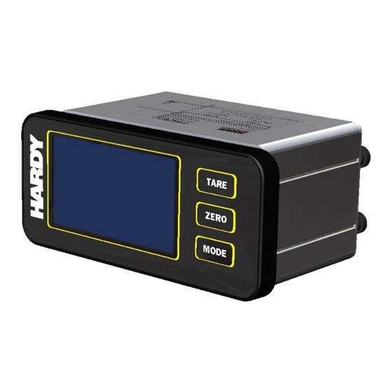
ZERO – press to reset the displayed weight to zero. • MODE – press to change modes (Gross / Net / Set-Up) • Soft buttons Set-up – press to access instrument configuration menu. • Hardy H6800 Series Application Controllers User Guide... - Page 16 Connect to a USB device. Dual 10/100 Mbps Ethernet ports Connect to a network switch or router. 24 VDC power Connect to DC power source. Optional AC power Connect to a 100-240 VAC power source. Hardy H6800 Series Application Controllers User Guide...
-
Page 17: Model H6850 Front And Rear Views
APPENDIX A - Shared Programming and Communications Options. Table 2-3. Front of the Model H6850 Item Description Front panel display Shows the information associated with the items selected using the soft buttons (touchscreen). Hardy H6800 Series Application Controllers User Guide... - Page 18 10 check weights in small font; press again to show the product recipe and again to return to the last check weight. Figure 2-4. Model H6850 Rear View without Option Cards Hardy H6800 Series Application Controllers User Guide...
- Page 19 Chapter 2 – Hardware Overview Figure 2-5. Model H6850 Rear View with AC Option Card Figure 2-6. Model H6850 Rear View with AC and GPIO Option Cards Hardy H6800 Series Application Controllers User Guide...
- Page 20 Chapter 2 – Hardware Overview Figure 2-7. Model H6850 Rear View with AC and GPRC Option Cards Figure 2-8. Model H6850 Rear View with AC and Scale Input Option Cards Hardy H6800 Series Application Controllers User Guide...
- Page 21 Connect to a USB device. Dual 10/100 Mbps Ethernet ports Connect to a network switch or router. 24 VDC power Connect to DC power source. Optional AC power Connect to a 100-240 VAC power source. Hardy H6800 Series Application Controllers User Guide...
-
Page 22: Installation
3 INSTALLATION Topics: This chapter describes how to install the HI6800 Series Application Controllers. Planning Your Installation (page 23) Unpacking and Climatization (page 28) Mounting Instructions (page 29) Wiring Instructions (page 37) Option Cards (page 45) ... -
Page 23: Planning Your Installation
Calibration & Preventive Maintenance • To request any of these services, or to discuss your needs with a trained Hardy Service Agent, call 800-821-5831 option 4 between 6:30 AM and 5:30 PM PST. For emergency downtime service after hours, leave a message in our emergency mailbox and your call will be returned promptly, or email us at hardysupport@hardysolutions.com. -
Page 24: User Responsibilities
Provide the space, people, and tools for unpacking, installing, and operating the HI6800 • Series Application Controller. Confirm that the path from where the HI6800 Series Application Controller is delivered to • the installation site is large enough to support the HI6800 Series Application Controller. -
Page 25: Electrostatic Discharge
Chapter 3 – Installation To ensure that visible damages or faults can be recognized, inspect the HI6800 Series • Application Controller at least once during a shift. Any changes in the operating performance must be reported immediately to the responsible authorities/persons. If necessary, stop and secure the HI6800 Series Application Controller until the reported issues are resolved. -
Page 26: Emergency Power Control
All pre-installation activities should be scheduled and completed before the equipment is delivered. The pre-installation process includes: Working with Hardy Field Service to ensure that all hardware and cables in the specified • configuration and all cables of the appropriate length have been ordered. -
Page 27: Seismic Considerations
Can the humidity level be maintained between 8% and 80%? Is the installation location protected against vibration and acoustics? Is all equipment not supplied by Hardy Process Solutions on site and ready for use? Electrical Requirements Is there a sufficient number of DC or AC outlets for the equipment? -
Page 28: Unpacking And Climatization
2. Remove the HI6800 Series Application Controller components and cables from the shipping container. 3. Save the shipping container, foam, and antistatic bags in case the HI6800 Series Application Controller must be returned. Returning the HI6800 Series Application Controller in any other container is not advised. -
Page 29: Mounting Instructions
Chapter 3 – Installation 3.3 Mounting Instructions 3.3.1 Mounting the Controller HI6800 Series Application Controllers can be mounted in the following configurations: Panel-mount option, using a 4.3-inch display or 7-inch display (Model HI6850 series only) • Remote Panel-mount when the instrument is mounted separately from the display. -
Page 30: Mounting Using A Front Panel Display
Figure 3-2. Panel Hole Dimensions (Not to Scale) A printable template is also available on the Hardy website. Printers and copy machines can distort or reduce the template measurements shown above. If you do not use the plastic template supplied with the product, verify the dimensional accuracy of any printed paper template before use. -
Page 31: Panel Mount Option
4. Align screw rods with the four holes drilled in the panel, then gently slide the display assembly until the gasket of the display is flush with the panel. Note: Rods are designed to accommodate a range of panel thicknesses (see the I/I diagram for detail). Hardy H6800 Series Application Controllers User Guide... - Page 32 8. Align the screw rods with the slots on the sides of the enclosure, then carefully slide the instrument about half-way onto the rods. 9. Plug the display cable into the instrument taking care not to twist the cable. Hardy H6800 Series Application Controllers User Guide...
- Page 33 11. Install and tighten the four keeper nuts, with the smooth side of the nut against the enclosure and the knurled side of the nut away from the enclosure. Caution: Do not over-tighten the four keeper nuts. Hardy H6800 Series Application Controllers User Guide...
- Page 34 Chapter 3 – Installation Figure 3-1. Zoomed-in View of Keep Nut Note: The HI6800 Series Application Controller front panel display is NEMA 4/4X rated when installed correctly in a panel per instructions above. Hardy H6800 Series Application Controllers User Guide...
-
Page 35: Din Rail Mount
3. Push the other side of the DIN rail bracket onto the DIN rail until it locks in place. 4. While holding the HI6800 Series Application Controller, gently pull up away from the DIN rail to verify that it is mounted correctly. -
Page 36: Remote Display Mount
Chapter 3 – Installation 3.3.2.3 Remote Display Mount The display for the HI6800 Series Application Controller can be mounted in a remote location. The display cable can be modified to support the desired length of cable (extra cable length is not supplied). -
Page 37: Wiring Instructions
The HI6800 Series Application Controllers contain power supply cards that require 24VDC power from a Class II power supply. Hardy Process Solutions advises that you wire directly to the Class II power supply instead of wiring to a 24VDC bus that supplies other devices. -
Page 38: Dc Power
Chapter 3 – Installation Figure 3-11. HI6800 Series Application Controller AC Input Power Terminal Block Optional AC Input Power Terminal Block Table 3-2. Pin Numbering on the Optional AC Input (100 -240VAC) Power Terminal Block Signal Name Properties Line AC/L... - Page 39 ‘ground loop’ when troubleshooting the scale stability issues. Ground loops can be of noise, hum, and interference in sensitive electronic systems a major source caused when two or more devices are connected to a common ground through different paths. Hardy H6800 Series Application Controllers User Guide...
-
Page 40: Ethernet Communications
Intranet, Extranet, VPN, or Internet (World Wide Web). Both ports support EtherNet/IP and Modbus TCP/IP protocols. Future support for OPC Unified Architecture (OPC UA) is under development. Ethernet Ports Figure 3-4. Ethernet Ports Hardy H6800 Series Application Controllers User Guide... - Page 41 Chapter 3 – Installation Table 3-4. Pin Numbering on the Ethernet Ports Signal Name TX− RX− Hardy H6800 Series Application Controllers User Guide...
-
Page 42: Connecting A Micro Usb Device
Note: Always store a SMM-SD card in a static-free enclosure within a secure environment to avoid losing the information stored on the card. Hardy H6800 Series Application Controllers User Guide... -
Page 43: Digital I/O
Chapter 3 – Installation 3.4.5 Digital I/O All versions of the HI6800 Series Application Controllers have Digital I/O, 2 inputs and 2 outputs. The Digital I/O is used to monitor input signals from peripherals such as buttons and switches (commonly used to initiate a print or tare command) or to drive peripherals such as status lights or motor starters. -
Page 44: Weigh Scale Input Connection
Model HI6850 can accommodate up to three additional weigh scale input connections for a total of four. The Primary weigh scale input connection is capable of 250 updates/second. It also features Hardy’s exclusive C2 ® and WAVERSAVER+ technology. -
Page 45: Option Cards
100 updates/second. They can also be used with almost all industrial load cells, sensors, and scales. These optional weigh scale input connections do feature Hardy’s exclusive C2 ® WAVERSAVER+ technologies. -
Page 46: Gpio Card
One analog input pin (4-20mA) featuring 16,000 counts of resolution. • Digital I/O (4 IN, 2 OUT) Four Analog Out One high-speed pulse One Analog In Figure 3-9. HI6850 with One Optional I/O Card Terminal Block Hardy H6800 Series Application Controllers User Guide... - Page 47 Digital I/O (8 IN, 2 OUT) Two Analog In Eight Analog Out Two high-speed pulses Figure 3-10. HI6850 with Two Optional I/O Card Terminal Blocks Table 3-7. Pin Numbering on the Optional I/O Card Terminal Block Hardy H6800 Series Application Controllers User Guide...
- Page 48 Sinking 0-24 VDC DIGITAL IN COMMON Field-side Ground (In1 & In2) Table 3-10. Pin Numbering on the Analog Input Port Signal Name Properties 4-20MA INPUT 5-32VDC input range COMMON 4-20mA input return (GND) Hardy H6800 Series Application Controllers User Guide...
-
Page 49: Relay Card
The Model H6850 supports up to two optional relay cards. Each block provides 8 pins for four DC relay connections, eight total per option card: Relay Option Card Figure 3-11. HI6850 with Two Relay Option Cards Hardy H6800 Series Application Controllers User Guide... - Page 50 NO, 5-30 VDC, 1A Common 2 Line 1 return (Gnd) Line 3 NO, 5-30 VDC, 1A Common 3 Line 1 return (Gnd) Line 4 NO, 5-30 VDC, 1A Common 4 Line 1 return (Gnd) Hardy H6800 Series Application Controllers User Guide...
-
Page 51: Profinet Card
3.5.4 PROFINET Card Model H6850 Application Controller supports up to one PROFINET interface card. This card must reside in the top option slot. See section A.5 for information about configuring the controller for PROFINET communications. Hardy H6800 Series Application Controllers User Guide... -
Page 52: Commissioning
4 COMMISSIONING This chapter describes how to commission the Connections (page 53) HI6800 Series Application Controllers. Powering on the HI6800 Series Application Controller (page 54) Hardy H6800 Series Application Controllers User Guide... -
Page 53: Connections
(AC or DC), weight scale input(s), Ethernet and any option cards that may be utilized. Check all connections before power-up by gently pulling on the leads to ensure there are no loose wires. Hardy H6800 Series Application Controllers User Guide... -
Page 54: Powering On The Hi6800 Series Application Controller
Chapter 4 – Commissioning 4.2 Powering on the HI6800 Series Application Controller The HI6800 Series Application Controllers come with a 24-VDC power supply. An optional 90-240 VAC power supply is available. The controller will power on as soon as it is connected to the appropriate power source. -
Page 55: Configuration
5 CONFIGURATION Topics: This chapter describes the ways to configure the HI6800 Series Application Controllers. It Accessing Configuration also describes the parameters that can be set. Parameters (page 56) Understanding the Home Screen (page 61) Understanding the Operation ... -
Page 56: Accessing Configuration Parameters
Chapter 5 – Configuration 5.1 Accessing Configuration Parameters There are several ways to configure HI6800 Series Application Controllers: Using the touchscreen (see section 5.1.1) • Using an Ethernet network connection and embedded webserver (see section 5.1.2) • Using a direct connection to a PLC, PAC, or DCS control system (see section 5.1.3) •... -
Page 57: Using An Ethernet Connection
Ethernet network via a router or switch. The rear panel of the application controller has two 10/100 BASE-T Ethernet ports for linking to any Windows personal computer. Once connected, Hardy firmware updates can be monitored, controlled, configured, or downloaded. The browser also provides links to the Hardy website, where additional services and support can be found. -
Page 58: Using A Direction Connection To A Plc, Pac, Or Dcs
5.1.3.1 DHCP Configuration Using the Front Panel Use the following procedure to prepare the application controller to use a DHCP configuration. DHCP works only if a DHCP server is installed on the network. Hardy H6800 Series Application Controllers User Guide... -
Page 59: Fixed Ip Configuration Using The Front Panel
Home screen. b. With the Operation Menu displayed, touch Communication under Setup. c. Under Manual IP assignment, note the fixed IP address, netmask, and gateway shown. Hardy H6800 Series Application Controllers User Guide... - Page 60 4. Open a browser on the PC. 5. In the address bar at the top of the browser, enter the application controller’s fixed IP address (example 192.168.0.100) and press Enter. The application controller Home screen appears in the browser. Hardy H6800 Series Application Controllers User Guide...
-
Page 61: Understanding The Home Screen
5.2 Understanding the Home Screen All configuration activities start from the Home screen. The Home screen appears when the HI6800 Series Application Controller receives power. Figure 5-3 shows Home screen and Table 5-1 describes the key areas. Note: Most parameters are the same for Models HI6800 and HI6850. However, certain specific applications such as checkweighing, batching, or rate control will have additional parameters available only on the Model HI6850. - Page 62 Tare = press to set the net (or tare) weight value. • Zero = press to set the gross weight to zero. • Mode = press to toggle the displayed weight between gross and net. • Hardy H6800 Series Application Controllers User Guide...
-
Page 63: Understanding The Operation Menu
Chapter 5 – Configuration 5.3 Understanding the Operation Menu The HI6800 Series Application Controller parameters are organized into the categories on the Operation Menu. Each screen has a disk and menu icons at the top right of the screen and an information icon at the top left that shows online help for the displayed screen. -
Page 64: Initial Configuration
Chapter 5 – Configuration 5.4 Initial Configuration When the HI6800 Series Application Controller is received for the first time, we recommend performing the following initial configuration. Figure 5-4. Initial Configuration Hardy H6800 Series Application Controllers User Guide... -
Page 65: Configuring Setup Parameters
Range: 16 alphanumeric characters Operator ID ID of the user who is going to operate or service the application controller. Enter any combination of letters and numbers that adequately identifies the user. Range: 4 alphanumeric characters Hardy H6800 Series Application Controllers User Guide... - Page 66 Setting more decimal points does affect the overall accuracy of the application controller. Adding decimal points will not improve a system accuracy beyond the specified ability of the load cell. Ranger: 0 - 5 Default: 2 Hardy H6800 Series Application Controllers User Guide...
-
Page 67: Configuring Filters
® present in all dynamic and static industrial weight control and measurement applications. By factoring out nearly all of the ambient vibratory forces, the HI6800 Series Application Controller can separate out the actual weight data from background noise caused by vibration. -
Page 68: Waversaver
Vigorous vibration and impacting require a lower frequency WAVERSAVER setting or increased ® Number of Average. Therefore, if you decrease the WAVERSAVER setting, reduce the Number of ® Average accordingly. Range: 1 - 255 Default: 10 Hardy H6800 Series Application Controllers User Guide... - Page 69 WAVERSAVER and Number of Averages settings. ® Default: 0.00 (turns off WAVERSAVER+) Get it automatically Variation These two parameters allow you to get the desired variation and motion threshold automatically. Motion Hardy H6800 Series Application Controllers User Guide...
-
Page 70: Setting Tare/Zero Values
Zero Tolerance Sets the weight unit limit from zero the application controller will accept as gross zero during the zeroing function (when you push the Zero button). Range: .000001 – 999999 Default 10.0 Hardy H6800 Series Application Controllers User Guide... -
Page 71: Configuring Communication Parameters
IP address of the DNS server that the application controller will use. User Datagram Protocol Hardy Port If you use the Hardy port, enter the Hardy port number. Manual IP Assignment Fixed IP If DHCP is OFF, enter the fixed (static) IP address that the application controller will use. -
Page 72: Configuring Security
Enables or disables level 1 security by pressing this icon. Level 2 Enables or disables level 2 security by pressing this icon. Change Password Press to set or change the password, enter a 4-digit password, and press DONE. Hardy H6800 Series Application Controllers User Guide... -
Page 73: Configuring Display Settings
Range: Single Channel Display, Multi-Channel Display, App-Specific Display Default: Single Channel Display Screen Brightness Sets the brightness of the screen. 1 is the darkest and 100 is the brightest. Adjustment Range: 1 - 100 Default: 55 Hardy H6800 Series Application Controllers User Guide... -
Page 74: Calibrating The System
C2 capabilities, such as the HI6800 Series Application Controller. Digital information within an HI C2- certified load sensor details its unique performance characteristics. The HI6800 Series Application Controller reads the performance characteristics of each load sensor and detects the number of load sensors in the system. - Page 75 Manila 1.000461 Tokyo 1.000886 Copenhagen 0.999075 Mexico City 1.002102 Vancouver BC 0.999653 Nicosia 1.00093 New York 1.000433 Washington DC 1.000601 Jakarta 1.002631 Oslo 0.998726 Wellington NZ 0.999399 Frankfurt 0.999579 Ottawa 1.000007 Zurich 0.999821 Hardy H6800 Series Application Controllers User Guide...
-
Page 76: Performing Traditional Calibration
Place a certified test weight on the scale. Use this field to select a value and press Do Cal High to conduct the Cal High calibration. If the calibration succeeds, the message Cal Completed OK appears briefly; otherwise, an error message appears. For corrective actions, see Chapter 7. Hardy H6800 Series Application Controllers User Guide... -
Page 77: Performing Multipoint Calibration
Press Do Point 3 Cal to conduct the calibration. If the calibration succeeds, the message Cal Completed OK appears briefly; otherwise, an error message appears. For corrective actions, see Chapter 7. Hardy H6800 Series Application Controllers User Guide... -
Page 78: Option Parameters
Range: None, OIML, CPA, NTEP, MC Default: None Warmup Delay Time Amount of time that must pass before weight data is displayed. The time can be up to two decimal points in minutes. Hardy H6800 Series Application Controllers User Guide... -
Page 79: Running It Tests
With the HI 6020IT or HI 6010IT Summing Junction Box and IT feature, the application controller can provide both average numerical values and values specific to each load cell, including PASS/FAIL values for each load cell, as shown in Table 5-4. Hardy H6800 Series Application Controllers User Guide... - Page 80 Sensor 1 1.449430 0.1201 PASS 3.59 PASS Sensor 2 -0.993904 0.0336 PASS 3.88 PASS Sensor 3 -6.785617 0.0661 FAIL 2.82 PASS Sensor 4 8.293720 0.0586 FAIL 3.33 PASS Reference — 1.9867 — 31.51 FAIL Hardy H6800 Series Application Controllers User Guide...
-
Page 81: Option Card Setup
Path: Home screen > Operation Menu > Option > Option Card Setup The Option Card Setup category configures specific option cards available to the system. For more information, see APPENDIX A - Shared Programming and Communications Options. Hardy H6800 Series Application Controllers User Guide... -
Page 82: Cleaning And Maintenance
6 CLEANING AND MAINTENANCE Topics: A preventive maintenance program will maximize the lifetime of the HI6800 Series Application Preventive Maintenance Controller and minimize the risk of unscheduled Schedule (page 83) down-time. Optimal performance will be achieved Cleaning the Unit (page 84) by regular cleaning of system components. -
Page 83: Preventive Maintenance Schedule
Use a soft cloth moistened with a mild solution of soapy water and a nonabrasive detergent such as a household detergent for plastic. Never use caustic chemicals (e.g., strong solvents, pure alcohol, concentrated acids, or bases), sharp/metal objects, or high pressure to clean the touchscreens. Hardy H6800 Series Application Controllers User Guide... -
Page 84: Cleaning The Unit
If adjacent machines are cleaned using high-pressure water hoses or steam, protect the • HI6800 Series Application Controllers appropriately. Do not use solvents to clean the HI6800 Series Application Controller because of the • possibility of damage. 6.3 Spare Parts Keeping spare parts in stock ... -
Page 85: Troubleshooting
This appendix describes procedures tests that can shorten the time for troubleshooting. In the unlikely Disassembly and event of a problem with the HI6800 Series Reassembly (page 86) Application Controller, use the information in this Error Messages (page 87) chapter to identify and resolve the problem. -
Page 86: Disassembly And Reassembly
Make sure that the assemblies and sub-assemblies are well supported and insulated • when doing any repairs on HI6800 Series Application Controllers. Place small fasteners, connectors, and electrical parts in closed containers so as not to • lose parts during reassembly. -
Page 87: Error Messages
Note: If a problem is isolated to a load cell, it may not mean the load cell is the damaged component. Mechanical imbalances and system piping stress (lack of piping vibration isolators, cables draped over pipes, etc.) can make a load cell appear to be the problem. Hardy H6800 Series Application Controllers User Guide... -
Page 88: Troubleshooting Using Integrated Technician
Section 7.4.7 Electrical inspection Section 7.4.8 Load sensor installation Section 7.4.9 Exceeds the Millivolt range. Out-of-range condition. Section 7.4.10 Blank display Section 7.4.11 SD card diagnostics and losing memory at power cycles Section 7.4.12 Hardy H6800 Series Application Controllers User Guide... -
Page 89: A1: Troubleshooting Instabilities On A Formerly Operating System
Chapter 7- Troubleshooting 7.4.1 A1: Troubleshooting Instabilities on a Formerly Operating System Hardy H6800 Series Application Controllers User Guide... -
Page 90: B: Troubleshooting Instabilities On A Formerly Operating System
Chapter 7- Troubleshooting 7.4.2 B: Troubleshooting Instabilities on a Formerly Operating System Hardy H6800 Series Application Controllers User Guide... -
Page 91: B1: Troubleshooting Instabilities On A Formerly Operating System
Chapter 7- Troubleshooting 7.4.2.1 B1: Troubleshooting Instabilities on a Formerly Operating System Hardy H6800 Series Application Controllers User Guide... -
Page 92: B1 (Continued): Troubleshooting Instabilities On A Formerly Operating System
Chapter 7- Troubleshooting 7.4.2.2 B1 (continued): Troubleshooting Instabilities on a Formerly Operating System Hardy H6800 Series Application Controllers User Guide... -
Page 93: C: Troubleshooting Instabilities On A Formerly Operating System
Chapter 7- Troubleshooting 7.4.3 C: Troubleshooting Instabilities on a Formerly Operating System Hardy H6800 Series Application Controllers User Guide... -
Page 94: E: Troubleshooting Non-Return To Zero (Must Be Connected To An It® Summing Box)
Chapter 7- Troubleshooting 7.4.4 E: Troubleshooting Non-Return to Zero (Must be Connected to an IT® Summing Box) Hardy H6800 Series Application Controllers User Guide... -
Page 95: F: Troubleshooting Individual Load Cell Millivolt Readings
Chapter 7- Troubleshooting 7.4.5 F: Troubleshooting Individual Load Cell Millivolt Readings Hardy H6800 Series Application Controllers User Guide... -
Page 96: G: Calibration Failed: Not Enough Counts Between Zero Weight And Span Weight
Chapter 7- Troubleshooting 7.4.6 G: Calibration Failed: Not Enough Counts Between Zero Weight and Span Weight This error occurs at the Span Weight parameter. Hardy H6800 Series Application Controllers User Guide... -
Page 97: H: Mechanical Inspection
Chapter 7- Troubleshooting 7.4.7 H: Mechanical Inspection Hardy H6800 Series Application Controllers User Guide... -
Page 98: J: Electrical Inspection
Chapter 7- Troubleshooting 7.4.8 J: Electrical Inspection Hardy H6800 Series Application Controllers User Guide... -
Page 99: K: Load Sharing And Load Sensor Checkout
Chapter 7- Troubleshooting 7.4.9 K: Load Sharing and Load Sensor Checkout Hardy H6800 Series Application Controllers User Guide... -
Page 100: M: (*******) Or
Chapter 7- Troubleshooting 7.4.10 M: (*******) or (- - - - - - -) Error Hardy H6800 Series Application Controllers User Guide... -
Page 101: N: Application Controller Front Panel Display Is Blank
Chapter 7- Troubleshooting 7.4.11 N: Application Controller Front Panel Display is Blank Hardy H6800 Series Application Controllers User Guide... -
Page 102: P: Sd Card Diagnostics
Chapter 7- Troubleshooting 7.4.12 P: SD Card Diagnostics Hardy H6800 Series Application Controllers User Guide... -
Page 103: Appendix A - I/O Setup
For example, with a set point value of 1000 pounds and a deadband set to 5 pounds, the relay would close at 1000 pounds but not open until the weight dropped to 995 pounds. Hardy H6800 Series Application Controllers User Guide... - Page 104 Setpoint target weight (or rate when option is available). A setpoint ON/OFF status change is based on this value combined with the effect of implementing Deadband and Preact limits. Type: The options determine which formula to apply: Hardy H6800 Series Application Controllers User Guide...
-
Page 105: Set Point Controller Parameters
A.2.1 Set Point Controller Parameters Path: Home screen > Operation Menu > App > Set Point Controller If your HI6800 Series Application Controller has access to the set point controller application, refer to the table below for configurable parameters. Parameter... -
Page 106: I/O Configuration
Digital Input changing state. Value: Indicates the current state of the input, 0 for low and 1 for high. Press or click Save Parameters once a nickname (optional) and Usage have been assigned. Hardy H6800 Series Application Controllers User Guide... -
Page 107: Main Board I/O
0Quck Reference A.4 Main Board I/O See the diagram below for the appropriate settings. Hardy H6800 Series Application Controllers User Guide... -
Page 108: Mapping
Any reference to the right side of the assignment statement refers to the data only and not the address, even though the address is listed. Memory Address (Variable) = Data (Values, states) Hardy H6800 Series Application Controllers User Guide... -
Page 109: Appendix B - Application-Specific Programming Options
B.3 Rate of Change Parameters Path: Home screen > Operation Menu > App > Rate Of Change If your HI6800 Series Application Controller has access to the rate of change application, refer to the table below for configurable parameters. Parameter... -
Page 110: Multi Channel Measurement
30ms and recalculates the ROC in a rolling-average scheme. Range: 1 – 600 Default: 1 B.4 Multi Channel Measurement B.5 Feed Weight Control B.5.1 Loss in Weight B.5.2 Gain in Weight B.6 Feed Rate Control Parameters Hardy H6800 Series Application Controllers User Guide... -
Page 111: Dynamic Checkweighing Parameters
Read-only field that shows the unit in which the weighing result is displayed. Target weight Ideal weight that is to be reached on a consistent basis. Trigger weight Weight reaches on the scale when the check starts. Hardy H6800 Series Application Controllers User Guide... -
Page 112: Quick Installation Guide
All HI6800 Series Application Controllers settings are application dependent, however these are some common items that may help reduce setup times. The HI6800 Series Application Controllers addendum on the 4050CW webpage has detailed setup information. Always use the Apply Edits function to save and/or run. -
Page 113: Programmers Quick Reference Guide
B.9 Belt Scale Weight Processing B.10 Belt Scale Feed Control B.11 I/I Diagrams and Drawings Interconnect and Installation I/I Diagrams are on the Hardy Process Solutions Website, under the respective product pages in the Tab Documents & Programs. https://www.hardysolutions.com/hi6800 https://www.hardysolutions.com/hi6850... -
Page 114: Appendix C - Installing Option Cards (Model Hi6850)
6. After the cards are installed, position the backplate over the enclosure and secure with the screws you removed in step 3. 7. Make connections to the option card as required. Hardy H6800 Series Application Controllers User Guide... -
Page 115: Appendix D - Glossary
Gateway Connects local devices such as your application controller to other networks. Human-Machine Interface A user interface or touchscreen that allows operators to interact with the HI6800 Series Application (HMI) Controllers. IIoT Industrial Internet of Things. An extension and use of the Internet of Things (IoT) designed for industrial sectors and applications. -
Page 116: Index
75 DIN rail mount, 35 traditional, 78 Disassembly and reassembly, 89 Cleaning Document conventions, 10 and maintenance, 85 Dynamic checkweighing, 115 unit, 87 Dynanic checkweighing parameters, 118 Climatization, 28 Commissioning, 51 Configuration, 56 Hardy H6800 Series Application Controllers User Guide... - Page 117 HI6800 Series Application Controller HI6800 Series Application Controllers, 22 calibration, 76 option cards, 122 cleaning, 87 planning, 23 cleaning and maintenance, 85 tools, 23 commissioning, 51 user responsibilities, 24 configuration, 56 Integrated technician troubleshooting, 91 Hardy H6800 Series Application Controllers User Guide...
- Page 118 Models, 12 setup, 66 Mounting Piece count, 114 controller, 29 Pin numbering DIN rail, 35 analog input port, 47 panel mount option, 31 analog output port, 47 remote display mount, 36 digital I/O, 42 Hardy H6800 Series Application Controllers User Guide...
- Page 119 49 Remote display mount, 36 Unpacking, 28 User responsibilities, 24 Required tools, 23 Responsibilities, user, 24 Warning labels, 24 Safety labels, 24 Weigh scale input Schedule of preventive maintenance, 86 card, 44 Hardy H6800 Series Application Controllers User Guide...
- Page 120 Micro USB device, 41 Weight Micro-SD card, 41 gain in, 114 ProFinet card, 50 loss in, 114 relay card, 48 monitoring, 115 weigh scale input card, 44 Weight measurement parameters, 116 weigh scale input connection, 43 Hardy H6800 Series Application Controllers User Guide...
- Page 121 Hardy Process Solutions 10075 Mesa Rim Road San Diego, CA 92121 hardyinfo@hardysolutions.com http://www.hardysolutions.com Hardy Process Solutions Document Number: 0596-0361-01 Rev. A Hardy H6800 Series Application Controllers User Guide...
Need help?
Do you have a question about the HI6800 Series and is the answer not in the manual?
Questions and answers