
Related Manuals for Hardy HI 4050


Summary of Contents for Hardy HI 4050
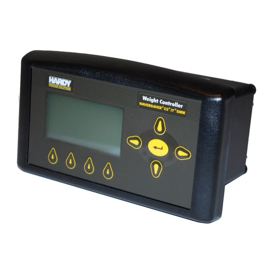
- Page 1 Weight Controller HI 4050 User’s Guide Hardy Process Solutions Document Number: 0596-0303-01 REV W...
- Page 2 Local Field Service Hardy has over 200 field technicians in the U.S., and more positioned throughout the world to assist you in your support needs. We also have factory engineers who will travel to your facility anywhere in the world to help you solve challenging applications. We're ready to support you with: •...
-
Page 3: Table Of Contents
Overview - - - - - - - - - - - - - - - - - - - - - - - - - - - - - - - - - - 1 General Introduction to the HI 4050 Weight Controller - - - - - - - - - - - - - 1... - Page 4 Update Rate - - - - - - - - - - - - - - - - - - - - - - - - - - - 9 Resolution - - - - - - - - - - - - - - - - - - - - - - - - - - - - 9 Display - - - - - - - - - - - - - - - - - - - - - - - - - - - - - 9 Display Increments (Graduations) - - - - - - - - - - - - - - - - - 9 Limits and Ranges - - - - - - - - - - - - - - - - - - - - - - - - - - - - 9...
- Page 5 Mechanical Installation - - - - - - - - - - - - - - - - - - - - - - - - - - - - 16 Installing the HI 4050 Weight Controller in a Panel - - - - - - - - - - - - 16...
- Page 6 Direct Connect Hardware- - - - - - - - - - - - - - - - - - - - - - - - - 44 Connecting a HI 4050 unit to a Laptop Computer - - - - - - - - - - - - - 44...
- Page 7 Type - - - - - - - - - - - - - - - - - - - - - - - - - - - - - - 93 HI 4050 Security - - - - - - - - - - - - - - - - - - - - - - - - - - - - - - - 94...
- Page 8 Mechanical Check Procedures - - - - - - - - - - - - - - - - - - - - - - 99 Electrical Check Procedures - - - - - - - - - - - - - - - - - - - - - - - 100 Calibration Procedures - - - - - - - - - - - - - - - - - - - - - - - - - - - - 101 C2 Calibration - - - - - - - - - - - - - - - - - - - - - - - - - - - - - - 101 Reference Weight - - - - - - - - - - - - - - - - - - - - - - - - 101...
- Page 9 Clear Button - - - - - - - - - - - - - - - - - - - - - - - - - - - 129 Zero Button - - - - - - - - - - - - - - - - - - - - - - - - - - - 129 Tare Button - - - - - - - - - - - - - - - - - - - - - - - - - - - 129 Print Button - - - - - - - - - - - - - - - - - - - - - - - - - - - 129 Entering Alphanumeric Values - - - - - - - - - - - - - - - - - - 129...
- Page 10 Ordering Replacement Parts - - - - - - - - - - - - - - - - - - - - - - - 169 Software Downloads for Your HI 4050 - - - - - - - - - - - - - - - - - - 169...
-
Page 11: Chapter 1 Overview
Hardy WebTech on our Hardy Web Site. Most problems can be resolved by the Hardy WebTech, 365 days a year, 24 hours a day 7 days a week. You can still contact a technician by phone during our normal operating hours (6:30 AM to 5:30 PM Pacific Time) if necessary. -
Page 12: Mounting Options
Controller), DCS (Distributed Control System) or computer network. NOTE The HI 4050 was recently updated to the HI 4050+. To support all users of the HI 4050, regardless of hardware configuration, this manual uses the term HI 4050 interchangeably with the HI 4050+, except in those matters specifically referring to the HI 4050+. -
Page 13: Enclosure Options
You can identify the new HI 4050+ on the startup menu, which displays the name 4050+. 4050+ indicates that this is a unit with the new high speed weigh scale card in it and with the new firmware that supports these features. -
Page 14: Connectivity
Connectivity The HI 4050 enables operators to use the selectable10/100 Base T Ethernet port and its embedded web server to link performance, diagnostics and setup data to and from your Intranet, Extranet, VPN or the Internet. The available communication interface lets you view and control multiple applications from a display and add third-party I/O to the system. -
Page 15: Integrated Technician
Model Numbers An example of a possible number: HI 4050-DR-AC-EIP-N2-N3 The abbreviations shown below indicate that the unit is an HI 4050 with a blind Din Rail mount that is AC powered with an EtherNet/IP communication port. Model Number Option Symbols... -
Page 16: Internal Options
The analog output is not isolated. An external 4-20 ma isolator may be required for stable readings. Digital I/O Option While the standard HI 4050 includes three built-in external digital inputs, the digital I/O card option adds three more digital inputs (isolated) and four digital outputs (non-isolated). •... -
Page 17: Rio Option
Rockwell programmable controllers. ControlNet Option ControlNet is an open network protocol used in industrial automation applications for linking an HI 4050 to any ControlNet-capable device (such as PLCs) Profibus Option The PROFIBUS-DP (Decentralized Peripherals) communication profile is designed for efficient field-level data exchange. The central automation devices, such as PLC/PC or process control systems, communicate through a fast serial (RS485) connection with distributed field devices, e.g. - Page 18 • • • Chapter 1 • • •...
-
Page 19: Chapter 2 Specifications
Specifications • • • • • • Chapter 2 lists the specifications for the HI 4050 Weight Controller. Specifications are listed for the standard instrument and for instruments fitted with optional equipment. The specifications listed are designed to assist in the installation, operation and troubleshooting of the instrument. - Page 20 Averages • 1 to 250 User Selectable in Single Increments Input • Up to 8 350-ohm Full Wheatstone Bridge, Strain Gauge Load Sensor/Cells per vessel • Signal Voltage Range: -.5 to16.5mV @ 5V Key Pad • 9 tactile keys, 4 Soft Keys (Mappable) Non-Linearity •...
- Page 21 Replaceable Lithium batteries - Panasonic model BR1220 3V, 35mAh or BR1225 3V, 48mAh - Rayovac model BR1225 3v, 50mAh Common Mode Rejection • 100dB @ 50-60Hz Environmental Ranges and Limits Operating Temperature Range Ordinary Locations • -10 to 40º C (14º to 104º F) using AC current •...
- Page 22 Physical Characteristics Panel Mount • Display: Width: 7.07” (179.7) Height: 4.05” (102.8) Depth from panel: 0.73” (18.4) • Case Dimensions:2.99” H x 5.65” W x 3.125” D (75.9 mm H x 143.51 mm W x 79.37 mm D) • Case Material: Aluminum Alloy (6063-T5) •...
-
Page 23: Ethernet Rj45
Resolution • 16,000 counts over 0 to 20mA and 0 to 10V range Accuracy 0.25% error typical, 0.5% max error over time/temperature • Digital I/O Card The Inputs and Outputs must be mapped. (See Chapter 6, Mapping) Outputs • Four non-isolated outputs •... - Page 24 • • • Chapter 2 • • •...
-
Page 25: Chapter 3 Installation
Chapter 3 Installation • • • • • • Chapter 3 covers unpacking, cabling, interconnecting and installing the HI 4050. Users and service personnel should be familiar with the procedures in this chapter before installing or operating the HI 4050. -
Page 26: Mechanical Installation
Step 4. Record the model number and serial number of the HI 4050. Store them in a convenient, secure location for reference when contacting Hardy Process Solutions Customer Service Department or to buy parts or firmware upgrades. Mechanical Installation Installing the HI 4050 Weight Controller in a Panel WARNING - YOU MUST INSTALL THE HI 4050 IN A NEMA 4X ENCLOSURE WHEN USING THIS INSTRUMENT IN A CLASS I DIV 2 ENVIRONMENT. - Page 27 PANEL HOLE DIMENSIONS (RETROFIT) CAUTION: We recommend installing the HI 4050 in a NEMA 4, 4X or IP 55 rated enclosure or better. ATTENTION Nous vous recommandons d'installer le HI 4050 dans un boîtier NEMA 4, 4X ou IP 55 ou mieux.
-
Page 28: Installing The Wall Mount Hi 4050Xxws Weight Controller
Step 6. Put the display cable and connector through the hole in the panel door or Panel cover and plug the display connector into the display header in the bezel. Smooth any sharp or rough edges. Step 7. Gently slide the electronic enclosure onto the threaded rods while making sure the display cable glides easily and does not kink. -
Page 29: Blind Units (No Display)
For this example we are recommending a 3/4" thick 24”x24” piece of MDX plywood, mounted flat and level to create a strong flat mounting surface for the HI4050PMWS and HI4050DRWS enclosure. It is very important to install the enclosure on a flat surface. When the four enclosure mounting screws are tightened on a warped surface the enclosures NEMA 4/4X seal will be jeopardized. -
Page 30: Din Rail Installation Hi 4050 Weight Controller
DIN Rail Installation HI 4050 Weight Controller Step 1. Snap the two DIN rail mounting feet (shown on right) into the two holes on the front panel of the electronic enclosure appropriate for the desired mounting orientation. Step 2. When installing, push the mounting feet until you hear a snapping sound. The snap means they are mounted correctly. - Page 31 Step 3. A Template is shipped with the instrument. Use a ruler to verify that the holes displayed on the template match the measurements displayed on the template. Use the template to cut the five holes required for mounting the display on a wall or on the door of an enclosure.
-
Page 32: Installing A Remote Slave Display
Step 6. Plug the Cable connector into the Remote Display header at the front panel of the Electronic Enclosure. Put the cable through the large hole you cut in the surface where you are going to mount the display. Smooth the large hole to prevent cable damage. -
Page 33: Connecting Two Displays
Ground (Gnd) Ground (Gnd) NOTE You can still configure and operate the HI 4050 from the Web Browser. Connecting Two Displays You can connect up to two displays by connecting one at the front panel and one at the rear panel. -
Page 34: Load Point Installation
Step 4. Always store the SMM-SD card in a static-free enclosure and in a secure environment so as not to lose the information stored on the card. Load Point Installation NOTE Use a torque screw driver to insure the smaller 4-40 screws are tightened to 7 inch/lbs (8.06 kg/cm) and the larger #6 and #8 screw to 10 inch/lbs (11.42 kg/cm) Rear Panel ®... -
Page 35: Non-C2 Load Point Connection
Step 1. Remove the factory-installed jumpers from the terminal block if you are connecting an 8-wire cable from the junction box. Step 2. Connect the cable (Recommended load cell cable: Hardy Solutions Part. # 6020- 0001) wires to the channel terminal block according to the cable color code. -
Page 36: Ac Input Power Wiring (-Ac)
Neu (Low neutral) Line (HI) • Earth Ground The HI 4050 is configured with a universal power supply rated from120 to 240 VAC. • Make sure the VAC power is shut off before installing the wires to the connector. •... -
Page 37: Dc Power Input (-Dc)
DC Power Input (-DC) WARNING - Do not operate with incorrect line voltage. To do so will result in property damage and/or personal injury. Make sure that the power source does not exceed 24 VDC. AVERTISSEMENT – Ne pas faire fonctionner le système avec le voltage inapproprié. -
Page 38: External Inputs 1-3
• Read the disassembly instructions before disassembly. If you find the instructions for disassembly unclear, contact Hardy Process Solutions, Technical Support Department for additional information and assistance. • Do not disconnect any electrical plug, connector or terminal unless an identification tag is present or one is attached. -
Page 39: Installing Printed Circuit Boards
Installing Printed Circuit Boards Step 1. Line up the Printed Circuit board with the grooves in the electrical enclosure NOTE The Main Board and options are installed assembled. We are showing the Main Board installation only for illustration purposes. Step 2. The rear panel is normally installed before the printed board assembly is installed. Step 3. -
Page 40: Installing Option Cards
Step 4. Use the four 6-32 x .1875 Phillips pan-head screws to fasten the rear panel to the electrical enclosure. Step 5. Use a torque screw driver and torque each screw to 10 inch/pounds. DO NOT OVERTIGHTEN! Step 6. To disassemble the printed circuit board assembly, reverse Steps 1-5. Installing Option Cards The option cards connect to the Main control board either from the network header or option slot header. - Page 41 Step 2. Through holes in the bottom of the option card allow you to plug the board stacker into the option slot header (J2) on top of the card. Align the card through holes with 20mm stacker pins. Option Slot header (J2) 2mm Board Stacker...
-
Page 42: Installing Labels
Step 4. Slide the board assembly into the chassis until it stops. Step 5. Use the four pan-head screws (6-32 x .1875”) to fasten the rear plate to the chassis. Installing Labels Step 1. After removing the protective cover off the label, align the label with the through holes on each side of the Option port. - Page 43 Le faire peut endommager le matériel et/ou provoquer des blessures sur personnel. WARNING - The Hardy Analog Card is the Analog Source. Do not connect the Analog card to another internal or external Analog Source. To do so may result in property damage and/or personal injury.
-
Page 44: Analog Output Wiring
Analog Output Wiring • Channel 1 -Voltage • Channel 2 - Current • Channel 3 - Voltage • Channel 4 - Current NOTE Use a torque connector screw driver to properly tighten the screw terminals to 7inch/lbs (8 kg/cm). Wiring the Digital I/O Option Card (-DIO) The digital I/O card plugs into either the Options or Network slot. -
Page 45: Installing A Card In The Network Slot
Step 2. Connect the power supply plus side to the relay coil. Step 3. Connect the return side of the relay to a DIO output terminal. Resettable Fuses A current exceeding the limit trips a thermal fuse. The fuses will trip if any of the outputs are shorted to a power supply, causing the output voltage to rise to a high logic voltage level. -
Page 46: Installing A Network Card Label
Step 4. Use the two pan-head screws (4-40 x.25”) to fasten the option card to the standoffs attached to the main controller board. Installing a Network Card Label Step 1. Peel the protective cover off the label. Step 2. Align the label with the through holes on each side of the Network port. -
Page 47: Wiring The Devicenet Card
+5V BUS NO CONNECT RXD/TXD - NO CONNECT Wiring the DeviceNet Card DeviceNet uses the 40-pin board stacker. Follow the procedure above under Installing Network Cards. Left to Right facing the HI 4050 rear panel: Black CAN- Blue Shield Uninsulated CAN+... -
Page 48: Network Status Leds
The ControlNet option requires standard BNC-type conectors. Both connectors should be used. if redundancy is required. Item Item ControlNet Connector A Network Status LED B ControlNet Connector B Network Status LED A Configuration Status LED Network Status LEDs State Indication Flashing Red (1 Hz) Incorrect node configuration, duplicate MAC ID etc. -
Page 49: Wiring The Modbus Tcp/Ip Option
HI4050 upon customer request. A key is required to enable the software. You can purchase the option with the Key by contacting your local Hardy Process Solutions Representative or Hardy Service Center. Chapter 4 describes the activation procedure. -
Page 50: Chapter 4 Configuration
Windows PC. Once connected, you can monitor, download Hardy software, or configure the HI-4050 from that PC. A Help function can assist you in setup or trouble-shooting. The browser also links to the Hardy Web Site where the user can find additional services and support. -
Page 51: Ip Setup
IP Setup If you have a blind unit, you must use the IP Setup utility to set the IP address instead of the front panel. Follow the steps below for a LAN or Direct Connection, but use the IP address from these steps in the IP Setup utility to configure the 4050. Refer to the section on IP Setup Program at the end of this chapter for more information. -
Page 52: Displaying The Complete Dhcp Ip Address
Step 7. Power-cycle the instrument to force it to enable the DHCP method for setting the IP address. (Step not required for HI 4050 software after version 1.7.0.0.) Step 8. Recall the Configuration / Instrument Setup / Ethernet / IP menu. If the DHCP configuration was successful, the DHCP: line will include an IP address provided by the network server. -
Page 53: Direct Connection
Any standard Ethernet cable with RJ-45 connectors at each end can be used to connect the HI-4050 to your PC. A ‘crossover’ cable is not required. Simply plug the cable into each instrument. Connecting a HI 4050 unit to a Laptop Computer Step 1. Find the weight controller’s IP Address Instrument Setup> Ethernet>... -
Page 54: Windows 7
Left mouse click on “Properties” Click the Radio Button for “Use the following IP address:” Type in the same first 3 octets from the instrument, but change the node (.xxx) by 1 number (example 192.168.200.124) Type 255.255.255.0 for the Subnet mask Back out by clicking “OK”... -
Page 55: Direct Connect Configuration - Hi-4050
Direct Connect Configuration - HI-4050 The HI-4050 must now be assigned a unique IP address that will connect to the Windows PC. There are two simple rules for the IP Address: • It must have the same network identifier as the computer •... -
Page 56: Options Setup From The Web Page
• Modbus TCP/IP • ControlNet • Analog Out • EtherNet/IP This enables the HI 4000 Series to communicate with many devices on the network, including PCs and PLCs. This means that you can map, configure and monitor all the HI 4000 series products from the front panel or your LAN, Internet, DeviceNet, ControlNet and Wireless Servers that are connected to the Network. -
Page 57: Devicenet
DeviceNet DeviceNet is an open network protocol for connecting the 4050 to PCs, PLCs or embedded controllers through a single cable interface. Signals from the 4050 can be used for external diagnostics and troubleshooting. Smart devices, such as sensors, push buttons, motor starters, simple operator interfaces, drives and other weight modules can also be linked with DeviceNet, and third-party I/O can be easily added to any system. - Page 58 Configuring DeviceNet from the Front Panel You can adjust the number of Bytes In and Bytes Out if your process requires a different configuration than the default 32 Bytes In and/or Out. Step 1. From the Configuration Menu, use the down arrow to select Options and press Enter to open the Options Menu.
-
Page 59: Remote I/O
For complete information about the remote I/O interface, see the HI 4000 RIO Manual. Step 1. To configure the Remote I/O from the Web Browser, from the HI 4050 Home page click Configuration; then click Options to display the Options Menu. -
Page 60: Blind Unit Operation Setup
Blind Unit Operation Setup An HI 4050-DR Rate Controller cannot be configured from the front panel as a blind unit. In a blind unit, the Remote I/O parameters are configured from the Web browser. - Page 61 Select Controller I/O Card on the Options menu to open the read-only I/O Card page. This page shows the Inputs and Outputs that are currently activated. You may need to refresh your web screen to view any changes to the inputs. To test the inputs, continuously activate the input and refresh the web page while the input is activated.
-
Page 62: Ethernet/Ip
Ethernet installations and the business world. IP provides a set of services that any two devices can use to share data. You will need a key number to enable EtherNet/IP. You can purchase a key number by contacting the Hardy Service Center or your local Hardy Representative. NOTE EtherNet/IP™ is a trademark of ODVA. - Page 63 Enter to save it. Note that the number displayed above is only for illustration purposes and is based on the serial number. Step 3. You will have to set the following parameters on your PLC in order to communicate with the HI 4050: • COMM FORMAT: SINT, INT, DINT, OR FLOAT. Recommended as DATA-INT •...
-
Page 64: Rate Of Change (-Roc) Option Configuration
Low flow rates require a longer time base than high flow rates. The HI 4050 measures weight to better than 1 part in 10,000. The formula below provides a general starting range. -
Page 65: Roc Configuration From The Front Panel
Rate of Change page. Step 2. In the ROC Key field, enter the Key number provided by Hardy. Step 3. Click Set Parameter. Wait a few seconds for the parameter to be saved in the instrument. Step 4. Click the left arrow to reopen the Rate of Change page. -
Page 66: Configuring Rate Of Change
Step 3. The Rate of Change is now enabled. Step 4. Press Exit to return to the Rate of Change Menu. Configuring Rate of Change Step 1. Select time Base to display the Time Base edit screen. The Time base value can be 1- 1800 seconds (default Step 2. -
Page 67: Modbus Tcp/Ip
Step 2. On the ModBus Options page, enter the key number in the Key field, and click Set Parameter to activate the Modbus option. Step 3. You can now map from your client (PLC) to the HI 4050 module via Modbus. • •... - Page 68 Find a copy of the Hardy Modbus-Link Software on the Documentation CD you received with your HI 4050 Instrument. If you do not have the CD that came with your instrument, download it from the HI 4050 Resources Web page. Double click the Hardy Modbus-Link .exe file to install the software on your PC.
- Page 69 Connection form. Step 3. If TCP/IP is not selected, select it from the pull-down list. Step 4. Type the address of the HI 4050 module you want to communicate with into the IP Address text box and click OK. The red “No Connection”...
- Page 70 (HFO) text field 0. Our example used 555.0000. Step 11. On the Hardy Modbus-Link page Display pull-down menu, select Float Inverse. The value we entered from the Mapping page appears to the right of the “00000 =” which is 555.0000 Step 12.
-
Page 71: Configuring Modbus - Tcp/Ip Over Ethernet (10 Socket Max.)
555 with 999, Multiple Registers displayed 999.0000. Step 15. Click Send. A pop-up shows that the Response from the HI 4050 was received. Step 16. Click OK. Configuring MODBUS - TCP/IP Over Ethernet (10 socket max.) Error Messages: •... -
Page 72: Analog Card Option Configuration
Analog Card Option Configuration The analog output card has four channels. Channels 1 and 3 produce a 0-10 volt (V) output. Channels 2 and 4 produce a 0-20 milliamp (I) output. The Voltage Low and High and Current Low and High are set to the default values 0-10 Volts output and 4-20 mA output. While there is normally no reason to change these values, they can be set to accommodate other ranges required for a PLC or operating environment. - Page 73 NOTE If you don’t want to change the Voltage Low and High and Current Low and High default values, start with the Low and High Weight values for your application. For assistance in configuring the Analog Output Card, click HELP at the top of the page.
-
Page 74: Configuring The Analog Card From The Web Browser
HI 4050 Analog Output Adjustment If the output from the analog output card does not match the output levels required for your system, there is now a method of recalibrating the output levels based on your system. - Page 75 Click the blue RIGHT arrow at the bottom of the screen. NOTE: If you are asked for a security code, enter the High security code. If you don’t know the password and cannot access this screen, see your system administrator. Normally, you will not need to manually adjust the gain or offset values.** •...
-
Page 76: Configuring The Analog Card From The Front Panel
**If these are changed, they will affect the output of the associated analog channel. NOTE In the following procedure you will use two known inputs and measure the actual output levels received. On the Analog Output Calibration page, shown above, enter the higher input as high and the lower as low. -
Page 77: Analog Out Mapping
Step 3. For V/I Out Low and V/I Out High, whether the value being configured is voltage or current depends the channel selected in step 4. Select V/I Out Low and use Enter to open the V/I Out Low edit form. Step 4. -
Page 78: Digital I/O Option Card
Digital I/O Option Card Configuration of the Digital I/O option card is done mainly as a mapping function that is explained in Section 6. However, you can open the screen to the right from the Configuration menu. Step 1. From the Configuration menu; select Options to open the options menu;... -
Page 79: Profibus® Configuration
The HI 4050 is a slave device. All data communication exchanges between a master and the HI 4050 originate from the master device. Each HI 4050 is assigned to one master and only that master may write output data to that HI 4050. Other masters may read information from any slave, but can only write output data to their own assigned slaves. -
Page 80: Initialization Process
Initialization Process To be able to add an HI 4050 to a Profibus-DP network, you need a PC and software such as Siemens Step 7™, Simatic Manager or equal, that allows the Profibus-DP PLC and the HI 4050 to exchange data. -
Page 81: Initialization Procedures
Step 4. Complete any additional configuration that is required by your PLC for initialization. Our initialization example is for a Siemens PLC. Your PLC initialization requirements may differ. Step 5. Install the *.GSD file for the instrument you connected to the Profibus Network. Initialization Procedures NOTE The examples come from the Siemens Step 7™, Simatic Manager Software. - Page 82 NOTE The HI 4050 Series Input and Output Sizes are expressed in words. 16 words input and 16 words output. Step 7. Click OK to set the Node Address. Step 8. The HI 4000 Series module appears in the Profibus Network.
-
Page 83: Dp State (Read Only)
Reads the baud rate at which the HI 4050 communicates with the Master Device. If “Error” appears it means that no data is being exchanged between the HI 4050 and a Master device. Press the Exit button until you return to the Summary display •... -
Page 84: Controlnet Option Card
To set the ControlNet Parameters: Step 1. For Node, enter the Control-Net address of the HI 4050 (1 to 99). (If the node # you use does not work, try a different #.) Step 2. For Words Out, enter the... -
Page 85: Parameters Configured
Parameters Configured Unit (of Measure) Parameter The Unit (of measure) parameter sets the scale to either English or Metric units. The Selections are: • Pounds (lb) - Default • Ounces (oz) • Pounds/Ounces (lb/oz) • Ton (Ton) Short ton • Kilograms (Kg) •... -
Page 86: Operator Id Parameter
On the Web page, enter a name to identify the instrument in the Instrument ID text field. We used “HI 4050.” On the 4050 display, use the Down arrow to select Instru- ment ID, then press Enter to > display the Instrument ID edit page. -
Page 87: Graduation Size Parameter
On the Web page, from the Decimal Point pull-down list, select the decimal position for this instrument. On the 4050 display: Step 1. Use the Down arrow to select Decimal Point displaying the current number of digits setting. Step 2. Press the Right or Left Arrow buttons to select the Decimal point position, then press Enter to save the selection. -
Page 88: A/D Conversion Rate Parameter
A/D Conversion Rate Parameter The HI 4050+ sample rate is selectable at 110 sps or 250 sps (samples per second). That is the number of weight samples that are available for communications and weight processing, whether the weight has changed or not. Note that this function is only available in the HI 4050+ On the 4050+ Display: From the Setup Menu, arrow down to select A/D rate. -
Page 89: Numaverages Parameter
On the Web Page: From the Setup Menu, arrow down to select A/D rate. Toggle between 110 or 250 to make your selection and hit Arrow down to Enter to select the desired rate. NumAverages Parameter The value you enter for Number of Averages (NumAverages) sets the number of weight readings used to compute a sliding average of displayed weight. -
Page 90: The Waversaver® Parameter
Mechanical noise (from other machinery in a plant environment) can be present in forces larger than the weight forces being measured. The HI 4050 is fitted with WAVERSAVER technology that eliminates the effects of vibratory forces present in all dynamic and static industrial weight control and measurement applications. -
Page 91: Waversaver+ Options: Variation_Thd And Motion_Thd
The WAVERSAVER® calculation speed is independent of the sample rate. The HI 4050 sample rate is selectable at 110 sps or 250 sps (samples per second). That is the number of weight samples that are available for communications and weight processing, whether the weight has changed or not. -
Page 92: Low Pass Filter Parameter
To configure WAVERSAVER+, set the WAVERSAVER and Numaverages parameters to establish the speed and required accuracy for dynamic weighing. Set the variation_thd to 0.0 and observe the peak to peak variation of the weight value. Then set the variation threshold parameter to be 1.5 times larger than the observed weight variation. Set the motion threshold to 1/3 of the observed peak to peak weight variation. -
Page 93: Motion Tolerance Parameter
On the 4050 display: Step 1. Press the down arrow to select Low Pass Filter. Step 2. Press the right arrow to toggle between ON or OFF. Step 3. Press Enter to save your choice. Motion Tolerance Parameter The value you enter for Motion Tolerance sets the amount of deviation to allow for your process. -
Page 94: Autozero And Autozero Tolerance Parameters (Gross Weight)
AutoZero. This does not override the Zero button. You can still press the Zero button to zero the HI 4050 at any time, but AutoZero is useful in applications where you are zeroing a scale quite often and don’t want to push the Zero button each time. -
Page 95: Tare Weight Parameter (Net Weight)
Step 5. When you have selected all the values, press Enter to save. Our example (for illustration only) shows 4.85 for our AutoZero Tolerance. Yours will vary depending on your application. Tare Weight Parameter (Net Weight) The value you enter for Tare Weight allows the user to avoid pushing the Tare button each time he/she weighs something. -
Page 96: Certification Parameter
Enter to save. LCD Contrast Parameter Note that the Instrument Configuration Setup page allows you to change the contrast on the HI 4050 display by clicking the Darker or Lighter buttons. To set the LCD Contrast Parameter from the 4050 display: Step 1. -
Page 97: Printer And Time Setup Parameters
Printer and Time Setup Parameters Printer / Scoreboard Setup The Print parameters can output values, e.g., the Gross, Net and Tare with a Rate of Change Option and weight units (lb, kg etc.), to either a Printer or a Scoreboard display. Print Mode: For all modes, the information sent to the printer includes terminal etc., the current time/current date, and the mode. -
Page 98: Setup From The 4050 Interface
Setup From the 4050 Interface Step 4. Use the down arrow to select Printer Setup, and press Enter to display the Printer Setup menu. > Step 5. Select Printer Mode. Step 6. To set the Printer Mode (If the option is >... -
Page 99: Setup From The Web Interface
Setup From the Web Interface Step 1. Click the right green arrow at the base of the Printer Setup form to open the Configuration - Date and Time form. Step 2. Enter the current hour, minute, day, month, year, and time zone in the appropriate text fields. -
Page 100: Set Points
However, setpoints are used mainly for mapping digital I/O communications between the HI 4050 and network devices (e.g., PLCs). You define the use of a setpoint value based on how you apply that value within a mapping equation. See Section 6 for mapping informa- tion. -
Page 101: Parameters
Parameters Deadband Limit, Preact Limit, and Type The Deadband limit is the difference between the set point and the reset. It is used to prevent rapidly fluctuating setpoint states once the set point is reached. For example, with a set point value of 1000 pounds and a deadband set to 5 pounds, the relay would close at 1000 pounds but not open until the weight dropped to 995 pounds. -
Page 102: Hi 4050 Security
Configuring HI 4050 Security from the Web Page Step 1. From the... -
Page 103: Setting Parameter Security
Step 2. Type in the High Security and Medium Security codes in the appropriate text boxes. To NOT set High and/or Medium Security Codes, enter 0. Step 3. For the field Front Panel TARE/ZERO Security, use the pull-down list to select the level of security for taring and zeroing the instrument from the front panel. -
Page 104: Configuring Security From The Front Panel
Step 3. Click next to the Parameter text for which you want to set a security code. Step 4. Add two dollar signs for High security or one (1) dollar sign for Medium security. Our example shows two (High security). Step 5. -
Page 105: Ip Setup Program (Necessary For Blind Hi-4050 Units)
Controllers>HI 4050 Single Scale Weight Controller>. Then click on the Tab “Docs & Programs" . Then download the IP Setup Program). To run the program, you must be on the same network as the HI 4050 and your firewall must be set to allow the process. •... - Page 106 When you run the the IP Setup program from a network computer, it will find the HI- 4050 and allow you to set its IP address. • • • Chapter 4 • • •...
-
Page 107: Chapter 5 Calibration
It is important that users and service personnel be familiar with the procedures in this chapter before installing or operating the HI 4050 Weight Controller. All calibration is done in the Gross mode. Be sure to follow all the procedures completely to insure that the weights read by the controller are accurate. -
Page 108: Electrical Check Procedures
• Make sure that nothing is draped over the scale/vessel or the load cell, such as a hose, electrical cord, tubes, or other objects. • Check to see that nothing comes in contact with the scale/vessel other than service wires and piping that have been properly mounted with flexible connectors. -
Page 109: Calibration Procedures
NOTE Load cell/point measurements can be checked with a digital voltmeter at the J1 connector on the rear panel or at the summing box of the HI 4050 or use Integrated Technician if you are using the IT Junction Box. - Page 110 NOTE Ensure that the scale system is clean and ready to receive product. This step establishes the gross zero reference. You must perform a C2 Calibration after setting the Gravity Correction or the correction factor won’t work. City Grav. Accel City Grav.
- Page 111 C2 Calibration From the Web Page From the Home Page, click Configuration to display the Configuration menu; then click Calibration to open the Calibration page. Step 1. In the “Ref Weight” text field, enter the reference weight for your application. Step 2.
- Page 112 If not, check to ensure that each load cell/point cable connection is securely fastened and that each load cell/point cable is not broken. On the HI 4050 web page, select Operations > Diagnostics >C2 and Weight and Voltage to determine which load cell/point is malfunctioning.
-
Page 113: Traditional Calibration
Step 8. Use the Down arrow to select C2 Cal, and press Enter to set the C2 Calibration. Step 9. A “Cal Completed OK” briefly appears on the screen indicating the C2 calibration was successful. A “Security Violation” message briefly appears if you lack the security level required to do a calibration. - Page 114 Step 4. Click the Do Cal Low button to do the Trad Cal Zero. A “Cal Completed OK” message appears briefly if the calibra- tion was successful. An Error number appears if the calibration was not successful. See the Error list in Chapter 8 for help in correcting the error.
- Page 115 Step 3. Use the Down arrow to select “Cal Low Do Cal, and press Enter to save. A “Cal Completed OK” message appears briefly if the calibration was successful. Step 4. An Error number appears if the calibration was not successful.
- Page 116 • • • Chapter 5 • • •...
-
Page 117: Chapter 6 Mapping
HI 4050 mapping is more flexible than the typical I/O addressing used in a PLC. Since the HI 4050 does not use predefined I/O addressing, you can tailor custom mappings to meet the unique requirements of your application. Whether... -
Page 118: How Mapping Works
Additional variables are identified in the mapping pull downs and list of mapping symbols. Input and Output Tables To transfer values from node to node (e.g. the HI 4050 and PLCs) during an I/O scan, each node has an Input Table, where incoming values from other nodes are received, and an Output Table that contains the values to be read by other nodes. - Page 119 Often, more than two devices are involved, so separate input and output tables having different addresses may be set up for data exchanges with each device. In an HI 4050 mapping equation, the right side is for data from its input table and the left side is for output.
-
Page 120: Local Input
Local Input This is mapping where the input side of the equation is a digital signal entering the HI 4050 via a connector (other than a network connection feeding into an input table). HI 40 0 Input HI 4050 Internal... -
Page 121: Example #1 Mapping To A Network Output
From the Web Browser let’s go through the process: Step 1. From the HI 4050 Home Page, click Configuration to view the Configuration menu. Step 2. Select Mapping to view the Configuration Mapping Setup form. The pull- down menus list... - Page 122 Step 2. A Word box and Select button appears to the right of the Network box. Select the word (location within the register to begin the value) and click Select. Avoid using a word that is already in use for that table. NOTE An address such as EFO2 means the following.
-
Page 123: Data Types
Step 7. Click Map to complete the Gross Weight to EtherNet/IP Float Out equation. The Gross Weight that is stored in the input table is now assigned to the EtherNet/IP Float Out output table and to the EtherNet/IP Network. The Map list, shown below, shows the new mapping. -
Page 124: Example #2 Mapping An Input
Example #2 Mapping an Input We next connect a remote switch for use in Tare operations, so we must map User Switch 1 (1 of 3 inputs to the HI 4050) to Tare. The assignment statement is: • Destination = Source •... -
Page 125: Simple Mapping Example From The Front Panel
Boolean Mapping In a Boolean equation, the destination (left side of the equation) is a Boolean term. It can have the value 0 (FALSE) or 1 (TRUE). The HI 4050 supports three Boolean operations: • AND - The symbol for “AND” in a Boolean Assignment Statement is “*”. -
Page 126: Example #3 Mapping An Network Input To A Local Output
DI - is the DeviceNet input table. • DO - is the DeviceNet output table. • HI - is the Hardy input table. • HO - is the Hardy output table. DeviceNet input tables and output tables are mapped to physical external devices using a ®... - Page 127 This sets the digital output #1 to high/low from the input selected. NOTE: HI 4050 network input is the source for the data from PLC output. The PLC can send instructions to the network (input(source) on the HI 4050 and in turn to the HI 4050 output (destination).
-
Page 128: Example #4 Mapping A Switch
Example #4 Mapping a Switch Step 1. To Map the control source (Digital Input 1) to a Control Source (Tare), return to the Configuration menu and select Mapping. Step 2. From the Control pull-down menu, select Tare (HO2.0). Step 3. Click Select. Tare (HO2.0) appears in the mapping field. -
Page 129: Command Word (Hso2) And Status Word (Hsi1)
HIS1 bit 11 (HI1.11) - SD memory card write failure When you send a command by setting a bit in HSO2, the command word, the HI 4050 will run that command and send a copy of the command bit sent back to the user in HSO2 being read. -
Page 130: Analog Mapping
An analog variable is addressed with the syntax below: [tablename][offset] The offset is an offset in words in the case of the network tables. The offsets in Hardy tables have various predefined meanings. When an analog equation is evaluated, all terms are converted to float. The final result is then converted to the type of the destination. -
Page 131: Special (Command) Mapping
By doing this you can set four-byte parameter values using a single command rather than the three commands required above. The Command Interface The HI 4050 may receive commands over any of its network interfaces. A command consists of four-bytes, which it receives through its network input data. -
Page 132: Performing A Parameter List (Dump)
• byte 0: The least significant byte of the PARAMTER ID • byte 1: The next byte of the PARAMTER ID but with the highest order bit set. • bytes 2,3: The value you want to set the parameter to. For example, to set the value of NumAverages to 3, if the first two-bytes are set to 0, send this hex command <0x8007><0x0003>. - Page 133 Step 3. Click Parameters to display a list of the parameters and their settings. 00000001 $Unit=4[kg]* 0001002A Data bits:=1[8] 00000002 $$Decimal Point=0[0]* 0002002A Parity:=0[NONE] 00000003 $$Grads=0[1]* 0003002A Printer Mode=2[TARE] 00000004 Operator ID=Me! 000002F2 scratchpad=3.000000 00000005 Instrument ID=Modular 000102F2 scratchpad=1.000000 00000006 WAVERSAVER®=3[1.00 Hz] 000202F2 scratchpad=1.000000 00000007 Num Averages=15 000302F2 scratchpad=3.000000...
-
Page 134: Using A Parameter Dump To Save Settings
Analog weigh scale card used in the HI 4050+. The differences in the cards prohibit a direct data transfer. That non-transferral of calibration data happens for new to old and old to new. -
Page 135: Chapter 7 Operation
Weight Controller. Being familiar with the operating procedures insures that the Controller will provide trouble free service. Getting Started Before operating the Hardy HI 4050 Weight Controller, check to make sure the following procedures have been performed: •... -
Page 136: Overview
Overview The Front Panel Display is a five-line Graphic LCD. The Summary screen displays the current weight in the selected mode (Gross, Net or available Rate of Change) and the selected engineering units (lb, oz, lb/oz, kg, g, Ton, t (Metric Ton). The screen displays the menus for Configuration, Calibration, Test and Operation. -
Page 137: Exit Button
Exit Button Exit returns to the previous menu. The Exit button only appears when you enter a menu, it does not appear on the Summary Display. Clear Button Clear (CLR) clears the total Alphanumeric Entry and repositions the cursor for the first entry. It is a good idea to clear an existing parameter value before entering a new value to avoid making mistakes. -
Page 138: Starting Up For The First Time
Starting Up for the First Time When the HI 4050 Weight Controller first powers, a Summary display shows the weight in Gross or Net mode. To change from Gross, Net or ROC (Rate of Change) mode, use the Mode button. -
Page 139: Using The Onboard Display Menus
Print parameters, press the Print button. Using the Onboard Display Menus After Startup, the display shows that this is a HI 4050+ with the new high speed weigh scale card in it with the new firmware. You can use the up and down arrow to scroll through the line options. -
Page 140: Set Points Configuration
This display with the “><” is an indication that the scale reading as at 0.00 +/- .5 grad. Pressing the MODE button will change the large number display between GROSS, NET, And ROC (if enabled) as show here with NET Selected. Set Points Configuration About Set Points Operators may need to reset a set point target weight. -
Page 141: Entering Set Points From The Web Page
Entering Set Points from the Web Page Click Configuration on the Home Page to open the Configura- tion menu, and select Adjust Setpoint to open the Adjust Setpoint page. Step 1. If your system uses more than one setpoint (up to four may be used), you will need to know which one you should change. -
Page 142: Entering Set Points From The Front Panel
Note the Setpoint Information is displayed below the Save Parameters button. This is read only and indicates the Setpoint you currently are configuring. The high or low is relative to the Target weight. Current weight and output condition is also high or low. Entering Set Points from the Front Panel All four set points are configured the same way. -
Page 143: Chapter 8 Troubleshooting
• • • • • • Chapter 8 provides procedures for troubleshooting the electrical, mechanical and firmware ® elements of the HI 4050 and for using Hardy’s Integrated Technician (IT ) software utility to isolate problems. Flow charts provide troubleshooting steps for the weight controller, load cells, and cabling. -
Page 144: Error Messages
If you are in doubt as to how to resolve a problem or if you need assistance, look for Hardy Process Solutions Web-tech at http://www.hardysolutions.com. Web-tech is updated often and is available 365 days a year 24/7. -
Page 145: Trouble Shooting Using Integrated Technician (It®)
• CAL Failed! - Too few counts between Zero and Span. • C2 Caps Unequal! - Different load cell capacities (For example 50 lbs capacity load cell and 100 lbs capacity load cell on one system. Make the load cells even be removing the uneven load cell and replacing it with a load cell that is equal to the others capacity. -
Page 146: Stability Test All
Integrated Technician Summing Junction Box © and using the IT Test section. ® NOTE is a registered trademark of Hardy Process Solutions. • • • Chapter 8 • • •... -
Page 147: Mv/V Are Dc Voltage Signals Between 0-3.0000 Mv/V
Millivolt/Volt equals the output from a load cell per each volt of excitation. The HI 4050 reads the load cell output in mV/V which is a higher resolution (4 decimal places) reading than a mV reading, thereby providing more sensitivity to enable you to troubleshoot the condition of the load cell in question under certain conditions. -
Page 148: Audit Trail
Audit Trail A list of parameters and successful calibration events is Audit Trail logged into the audit trail section. Event listings are formatted with a time and date stamp. Log entries cannot be erased and are stored in the Secure Memory Module. •... -
Page 149: General Troubleshooting Flow Chart Index
General Troubleshooting Flow Chart Index Drifting or unstable weight readings Electrical, Mechanical and Configuration reviews Drifting or unstable weight readings Weight indication will not return to zero Verify individual load sensor operation Trad. Cal - A/D Failure Error Mechanical Inspection Electrical Inspection Load Sensor Installation Exceeds the Millivolt range. -
Page 150: A - Guidelines For Instabilities On Formerly Operating Systems
A - Guidelines for Instabilities on Formerly Operating Systems Press the ENTER Button and arrow to the TEST prompt and press ENTER. Select the Stability Test and press ENTER This is a Pass or Fail test with the Variance displayed. Monitor the Test The variance is the results... -
Page 151: A1 - Guidelines For Instabilities On Formerly Operating System (Cont'd)
Monitor the Display for stability STABLE? Reconnect signal Problem could be in cables one at a the instrument. Contact time Hardy Customer Support PH: 800-821-5831 Monitor the display for stability If installing any cable causes Go to unstable readings REVIEW TROUBLESHOOTING SECTION B: B1.1-B1.7... -
Page 152: B - Guidelines For Instabilities On Formerly Operating Systems (Cont'd)
B - Guidelines for Instabilities on Formerly Operating Systems (Cont’d) Check for Electrical Stability Check for Mechanical Stability Check Configuration settings for stability Go To Stability • • • Chapter 8 • • •... -
Page 153: B1 - Guidelines For Instabilities On Formerly Operating Systems (Cont'd)
B1 - Guidelines for Instabilities on Formerly Operating Systems (Cont’d) Electrical Physical Grounding - All common equipment share a common ground point. B1.1 Keep the ground cable length to earth ground as short as possible. Install a new ground rod if the cable length is excessive. Cable - Cuts or breaks in the load cell insulation allow moisture to wick into the B1.2... - Page 154 B1 - Guidelines for Instabilities on Formerly Operating Systems (Cont’d) Vessel - When inspecting a vessel, keep in mind the Center of Gravity (COG) should be low and centered equally over all the load cells. Insure the load is directly over or under the load point to avoid side-loading. Make sure there isn’t any side loading from piping or external forces.
-
Page 155: C - Guidelines For Instabilities On Formerly Operating Systems
COMPLETE If you are unable to isolate the instability: Compare your results by testing the vessel when empty and then re-testing under load. Go to B for additional system checks Contact Hardy Instruments Customer Support PH: 800-821-5831 • • •... -
Page 156: E - Non-Return To Zero
® E - Non-Return to Zero (Must be connected to an IT Summing Box When empty Check for product buildup or Gross weight mechanical problems. Using the not equal to ZERO command if within the zero. ZEROTOL limits can zero the vessel This program level checks, records and Enter TEST mode and start the... -
Page 157: F - Verify Individual Load Cell Millivolt Readings
F - Verify Individual Load Cell Millivolt Readings • Testing an individual load cell signal output requires an IT Summing Junction box or millivolt meter. • Use the load cell certificate to verify the millivolt per volt (mV/V) rating: Example: 3mV/V load cells produce approximately 15mV at full load. That is 5 volts excitation x 3 mV/V. -
Page 158: G - Calibration Failed: Not Enough Counts Between Zero And Span
SPAN WEIGHT to Small 1000 counts out of 985,000 is very small. (100,000 lb. Scale would require a minimum of 101 lbs. ERROR? Contact PROCEED Hardy Instruments WITH Customer Service CALIBRATION 800-321-5831 Ext. 1757 •... -
Page 159: H - Mechanical Inspection
H - Mechanical Inspection 1) Keep flexures on the horizontal 2) Vertical flexures should be avoided 3) Do not use flexures to correct for misaligned piping 4) Do not use hose flexures to make right angle bends 5) Non-flexed piping should have an unsupported horizontal run using a ratio of 36 times it’s diameter 6) Pipe flexure lengths should be a ratio of 6 times it’s diameter 7) Feed and discharge piping flexed... -
Page 160: J - Electrical Inspection
J - Electrical Inspection DO NOT POWER UP THE CONTROLLER UNTIL INPUT VOLTAGES CAN BE VERIFIED 1) Verify the proper input power, AC or DC, is properly installed 2) Use a meter to verify neutral, ground and hot are correct 3) Computer grade power 4) Use Active filters for motor noises and spikes 5) Use isolation transformers to combat surges and sags... -
Page 161: K - Load Sharing And Load Sensor Checkout
K - Load Sharing and Load Sensor Checkout 1) Does the mV signal increase in a positive direction 2) If you receive a negative result, check if load cell is mounted correctly. (a) The arrow goes with the direction of force (b) If there isn’t an arrow, you must manually verify the correct direction. - Page 162 (b) Use IT TEST to verify Millivolt levels 5) Review Mechanical and Electrical Flow charts for additional tips. B1 6) Sense connection missing ERROR? Contact PROCEED WITH Hardy Instruments WEIGHING Customer Service PROCESS 800-321-5831 • • •...
-
Page 163: N - Weight Controller's Front Display Is Blank
Measure excitation voltage, 5 VDC? Disconnect all the connectors from the back panel except power Contact Hardy Instruments Customer Service Measure 800-821-5831 excitation voltage, 5 VDC? 1) Reconnect the jacks one at a time checking the 5VDC excitation. -
Page 164: P - Sd Card Diagnostics And Losing Memory At Power Cycles
EtherNet I/P port and a computer, to enter the Operations Diagnostics, SD CARD read Params selection Select: SAVE and Parameters EXIT, then intact? cycle power Contact Hardy Instruments Customer Service for additional instructions and possible return for repair • • • Chapter 8 •... -
Page 165: Tests And Diagnostics
Diagnostic page or the front panel Test menu. Each test is described in its own subsection below. You can also obtain information that a Hardy representative may ask for if you make a request to Technical Support. For example, for the last calibration, you can see the type of calibration and when it was done. -
Page 166: Parameters
NOTES The values entered in the Test Menu are for illustration purposes only. Your values will vary. To download the latest firmware version, visit the Hardy Solutions web page select Products> Weighing Instruments> Weight Controllers> HI 4050 Single Scale Weight Controller and then select the Docs &... -
Page 167: System And Load Cell Tests
This can be done using either tension or compression type load cells/points. When the HI 4050 sends the load cell a 5-volt DC excitation signal that powers the load cell, the force transducer generates a millivolt output proportional to the load (0-10mv DC for 2mv/V load cells/ points or 0-15mv DC for 3mv/V load cells/points). -
Page 168: Integrated Technician
With the HI 215IT Summing junction box and IT firmware, the HI 4050 can provide both average numerical values and values specific to each load cell, including PASS/FAIL values for each load cell, as shown below. -
Page 169: Stability Test
To view this screen on your system, see Weight and Voltage Tests. The number for a load sensor is based on the connections in the IT junction box. Check the installation sequence in the box to determine which load sensor is number 1, 2 and so on. You can use the IT functions from either the front panel or Web interface. -
Page 170: Weight And Voltage Tests
Running the Stability Test from the front panel Step 1. From the Test menu, select Stability Test with use the down arrow and press Enter. The HI 4050 runs the test and shows the results. Step 2. To see the AD/Raw Count and the A/D Average select them from the menu. - Page 171 Instrument (most likely improper wiring). If all the load sensor readings are 0.00, something is wrong between the HI 4050 and the HI 215IT junction box or with the junction box itself. Either the cable is disconnected, or something is causing the junction box to not transmit the readings to the HI 4050.
- Page 172 Running the Weight and Voltage test from the front panel The same information can be obtained from the front panel. From the Test menu, select > Weight and Voltage and press Enter to show the menu. Then select IT Test to run the test. To read the rest of the results, press the down arrow. The weight and voltage/reading raw counts and average are shown below.
-
Page 173: Return To Zero Test
Step 1. To select a Sensor, use the up or down arrows to move through the list, and press Enter to display the sensor IT Test results for the selected sensor. Our example looks at Sensor number 1. > Step 2. The output values will appear on the Sensor 1 menu. -
Page 174: Viewing System C2 Load Sensors
C2 load sensors in the system. When you press the Read Sensor button, it receives the information from the first load sensor. The serial number is important if you need to contact Hardy Process Solutions Technical Support. You do not need an IT summing box. -
Page 175: Smm-Sd Card Directory
SMM-SD Card Directory If your computer is equipped with an SD card reader, you can click on SD Card to display the SD Card page indicating the Write Protect status and listing the base directory with the files where the non-volatile memory is located for the HI 4050. -
Page 176: Audit Trail And Event Log
Audit Trail and Event Log The Audit Trail is a log of changes made to select parameters and calibrations that are monitored for NTEP rated instruments. It lists the date and time and whatever transaction performed. The Event Log shows startup dates and times. On the Web interface, click the Event Log or Audit Trail link at the bottom of the Operations - Diagnostics page. -
Page 177: General Policies And Information
NOTE For all non-warranty repairs a purchase order or credit card information is required. You can also go to the Hardy web site and request a Return Authorization number. An RA# will be e-mailed to you. http://www.hardysolutions.com/service/repair.php Ordering Replacement Parts Contact the Hardy Process Solutions Sales Department to order replacement parts and option boards. - Page 178 Step 1. In a web browser, go to www.hardysolutions.com/4000_support/index.html to open the HI 4000 Series On-line Support Site, and click HI 4000 Download Section. Step 2. This will display the screen shown below which can be used to download software for HI-4000 Series instruments. •...
- Page 179 Update button. Step 8. You should now be asked for a User Name and Password. Username is hardy and password is updatepass (all one word in lowercase letters). If Update does not give you the Password screen, the path to your program file may be too long. Try moving your files up to your root directory and run again.
-
Page 180: Warranty
A warranty problem may be handled by returning the product to the factory for repair or replacement under warranty. In the event you experience a problem with this instrument contact your local Hardy Representative or the Hardy Process Solutions Service Center to determine if the problem is covered under warranty. -
Page 181: Appendix A About Timezones
Appendix A About Timezones • • • • • • Greenwich Mean Time There are 25 integer World Time Zones from -12 through 0 (GMT) to +12. Each one is 15° of longitude as measured East and West from the Prime Meridian of the World which is at Greenwich, England. - Page 182 Civilian Time Zones Cities Abu Dhabi, UAE Muscat Tblisi Volgograd Kabul +4:30 Afghanistan +5:30 India +6:30 Cocos Islands CCT: China Coast Shanghai, China Hong Kong, China Beijing, China JST: Japan Standard Tokyo, Japan Osaka, Japan Taipei, Taiwan +9:30 Australian Central Standard Darwin, Australia Adelaide, Australia GST: Guam Standard...
- Page 183 Civilian Time Zones Cities Brasilia, Brazil Buenos Aires, Argentina Georgetown, Guyana -3:30 Newfoundland AST: Atlantic Standard Caracas, Venezuela La Paz EST: Eastern Standard Bogota, Colombia Lima, Peru New York, NY, USA CST: Central Standard Chicago, Illinois, USA Mexico City, Mexico Saskatchewan, Canada MST: Mountain Standard Phoenix, Arizona...
- Page 184 • • • Appendix A • • •...
- Page 185 INDEX Symbols basic load cell theory 48, 75, 89 Baud Rate !C2 Caps Unequal! Binding on the Load Cell !Function Error! board stacker pins !Not Allowed! Boolean Mapping !Security Violation! Boolean tables “clean” primary line Boolean variable *.gsd file Byte Count Error Numerics Bytes 5 VDC excitation...
- Page 186 Configuring Profibus Front Panel Do Cal Low button Configuring Rate of Change DO is the DeviceNet output image table Configuring Rate of Change Browser Configuring Security Do IT Test Configuring the instrument Do Trad Cal, (Zero) Connection pull down menu DP State (Read Only) 28, 135 Connector...
- Page 187 HI 3000 Series Network LCD Contrast HI 3000 Series Network configurations least significant byte HI 4050 live load HI 4050 Series (ANYBUS) module load (Vessel + Contents) HI 4050 web page load (weight) HI - Hardy input image table load cell I&M manual...
- Page 188 Modbus Float Out 166, 172 Modbus Key Ordering Replacement Parts Modbus Key menu original point of remova 53, 59 Modbus TCP/IP original point of removal Model Numbers Output Resistance Motion Error Output Voltage 159, 168 Motion Tolerance Overview of Typical Load Cell motor starters Mounting Options Mv/V and MV...
- Page 189 Stability Test Response OK pop Stability Test ALL Response pop up Standard Communication 56, 89 Starting the HI 4050 ROC Configuration Front Panel Starting Up for the First Time ROC Key Station Address Dialog box ROC Key menu Storage Temperature Range...
- Page 190 Temperature Coefficient Tension or Compression load cells Value Error tensions control vertically passing Test Menu vibration analysis The Command Interface Viewing System C2 Load Sensors Time Base Menu Viewing the SMM-SD Card Time Measure Voltage Time Measure pull down menu Time Zone Timebase text field Warranty...
- Page 192 9440 Carroll Park Drive, San Diego, CA 92121 Telephone:1-800-821-5831 FAX: (858) 278-6700 Web Address: http://www.hardysolutions.com Hardy Process Solutions Document Number: 0596-0303-01 REV W Copyright 2008-2013, Hardy Process Solutions, All Rights Reserved. Printed in the U.S.A.
Need help?
Do you have a question about the HI 4050 and is the answer not in the manual?
Questions and answers