Table of Contents
Advertisement
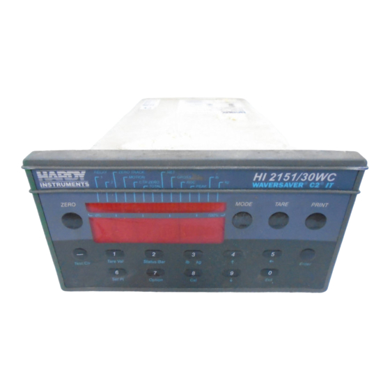
HI 2151 SERIES WEIGHT CONTROLLERS
REMOTE I/O OPTION
OPERATION AND INSTALLATION
MANUAL
Corporate Headquarters
9440 Carroll Park Drive
San Diego, CA 92121
Phone: (858) 278-2900
FAX: (858) 278-6700
Web-Site: http://www.hardysolutions.com
Hardy Process Solutions Document Number: 0596-0173-01 Rev L
Copyright September 2011 Hardy Process Solutions, Inc. All Rights Reserved. Printed in the U.S.A. (941028)
Advertisement
Table of Contents

Related Manuals for Hardy HI 2151 Series


Summary of Contents for Hardy HI 2151 Series
- Page 1 Corporate Headquarters 9440 Carroll Park Drive San Diego, CA 92121 Phone: (858) 278-2900 FAX: (858) 278-6700 Web-Site: http://www.hardysolutions.com Hardy Process Solutions Document Number: 0596-0173-01 Rev L Copyright September 2011 Hardy Process Solutions, Inc. All Rights Reserved. Printed in the U.S.A. (941028)
- Page 2 Local Field Service Hardy has over 200 field technicians in the U.S., and more positioned throughout the world to assist you in your support needs. We also have factory engineers who will travel to your facility anywhere in the world to help you solve challenging applications.
-
Page 3: Table Of Contents
Table of Contents TABLE OF CONTENTS TABLE OF CONTENTS - - - - - - - - - - - - - - - - - - - - - - - - - - - - - - - - - - - - - - - - I TABLE OF ILLUSTRATIONS - - - - - - - - - - - - - - - - - - - - - - - - - - - - - - - - - - - - - I LIST OF TABLES - - - - - - - - - - - - - - - - - - - - - - - - - - - - - - - - - - - - - - - - - - - A CHAPTER 1 - OVERVIEW - - - - - - - - - - - - - - - - - - - - - - - - - - - - - - - - - - - - - - - 1-1... - Page 4 HI 2151 SERIES WEIGHT CONTROLLERS REMOTE I/O OPTION Block Read Command Number 3: Instrument Identification and Diagnostics - - - - - - - - - - - - - 5-6 Block Read Command Number 4: Read Tare Value - - - - - - - - - - - - - - - - - - - - - - - - 5-7...
-
Page 5: Table Of Illustrations
Table of Illustrations TABLE OF ILLUSTRATIONS CHAPTER 2 - INSTALLATION - - - - - - - - - - - - - - - - - - - - - - - - - - - - - - - - - - - - - 2-1 FIG. - Page 6 List of Tables LIST OF TABLES CHAPTER 2 - INSTALLATION - - - - - - - - - - - - - - - - - - - - - - - - - - - - - - - - - - - - 2-1 TABLE 2-1 CABLE TERMINATION REQUIREMENTS - - - - - - - - - - - - - - - - - - - - - - - - 2-1 CHAPTER 3 - SETUP - - - - - - - - - - - - - - - - - - - - - - - - - - - - - - - - - - - - - - - - - 3-1...
- Page 7 HI 2151 SERIES WEIGHT CONTROLLERS REMOTE I/O OPTION TABLE 6-2 RELAY STATUS - - - - - - - - - - - - - - - - - - - - - - - - - - - - - - - - - - - - - 6-1...
-
Page 8: Chapter 1 - Overview
HI 2151WC controller. Each Hardy HI 2151WC represents a quarter (1/4) rack of discrete I/O (32 bits in the PLC Output and Input image files) to the scanning PLC and supports both discrete and block transfers. -
Page 9: Common Applications
This product incor- porates technology which is licensed by Allen-Bradley Company Inc. Allen-Bradley does not technically approve, warrant or support this product. All warranty and support for this product is provided by Hardy ® ®... - Page 10 Chapter 1 - Overview or can be entered as a numeric value via the keypad on the front panel of the HI 2151WC. This new tare value is the reference point for Net Weight. TV = G - N TV = Tare Value (weight) G = Gross Weight N = Net Weight...
-
Page 11: Chapter 2 - Installation
Chapter 2 - Installation CHAPTER 2 - INSTALLATION Remote I/O Board Cable Termination Dip Switch Configuration About Cable Weight controllers are connected to a cable in daisy-chain fashion and Termination are referred to as “nodes”. A Daisy Chain is a hardware configuration in which devices are connected one to another in a series. -
Page 12: Installing The Rio Option Board
HI 2151 SERIES WEIGHT CONTROLLERS REMOTE I/O OPTION Step 2. On the last RIO board in the daisy chain, select the desired switch settings in Table 2-1 for Baud Rate. NOTE: The cable lengths used in Table 2-1 are maximum lengths that can be used in the daisy chain. -
Page 13: Chapter 3 - Setup
Chapter 3 - Setup CHAPTER 3 - SETUP Remote I/O Setup Bargraph LEDS While the RIO menu is displayed, the Bargraph LEDs have the follow- Secondary ing secondary functions. Functions (HI 2151/ 20WC only) A. The Zero Track LED displays the status of the “Green LED” on the RIO. -
Page 14: Setup Procedures
HI 2151 SERIES WEIGHT CONTROLLERS REMOTE I/O OPTION Setup Procedures Step 1. Enter the Option Menu by pressing the 7/Option button. (Dis- play shows the first option available) Step 2. Press the up arrow until RIO is displayed on the screen. -
Page 15: About Blind Units
Chapter 3 - Setup About Blind Units An HI 2151WC Weight Controller that cannot be programmed or con- figured from the front panel is a blind unit. In a blind unit, the Remote I/O parameters are configured using both the interior and exterior dip switches. - Page 16 HI 2151 SERIES WEIGHT CONTROLLERS REMOTE I/O OPTION Step 3. Set the Exterior Dip Switches. (See Table 3-3) EXTERIOR DIP SWITCHES Switch Position - S3 which is located on the Rear Panel B5 (32) B4 (16) B3 (8) B2 (4)
-
Page 17: Chapter 4 - Discrete Transfers
Chapter 4 - Discrete Transfers CHAPTER 4 - DISCRETE TRANSFERS Discrete Writes The PLC places two sixteen bit words in the Output Image Table which are read by the HI 2151WC weight controller. The second word defines which weight data the HI 2151WC should place in the Input Image Table for the PLC to read. -
Page 18: Status Byte
HI 2151 SERIES WEIGHT CONTROLLERS REMOTE I/O OPTION Status Byte Select two of the status bytes below to be placed in the PLC Output Image Table. Definitions of the status bits contained in each status byte: 0 = Relay Status Byte... -
Page 19: Dipswitch Settings (Exterior) Status Byte
Chapter 4 - Discrete Transfers 1 = Remote bit 0 Force display to Rate-of-Change mode Function Status bit 1 Add current net weight to total Byte bit 2 Hold value on display bit 3 Hold option card updates bit 4 Force display to Net Weight mode bit 5 Toggle lbs/kg... -
Page 20: Dipswitch Settings (Interior) Status Byte
HI 2151 SERIES WEIGHT CONTROLLERS REMOTE I/O OPTION 5 = Dipswitch bit 0 Reserved for future use Settings (interior) bit 1 Enables gross weight output on RS232 port once per second Status Byte bit 2 Calibration lockout for NTEP (Legal for Trade) mode... -
Page 21: Chapter 5 - Block Transfers
Chapter 5 - Block Transfers CHAPTER 5 - BLOCK TRANSFERS About Block Transfers The ladder logic programmer is able to exchange blocks of data with a 1/4 rack device via Block Transfer instructions in the ladder logic pro- gram. A Write Block Transfer is used to send commands and data to the Weight Controller, and a Read Block Transfer is used to collect acknowledgments and data from the Weight Controller. -
Page 22: Block Read Command Number 1: Full Status And Weight Data
HI 2151 SERIES WEIGHT CONTROLLERS REMOTE I/O OPTION information with the read command number repeated in the first byte of the block returned. If a data error is detected, an error code “99” is in the first byte of the returned block. -
Page 23: Chapter 5 - Block Transfers
Chapter 5 - Block Transfers BLOCK READ COMMAND NUMBER 1: Full status and weight data START WORD DEFINITIONS: #WORDS WORD Dipswitch Settings (interior) Status bit 0 Reserved for future use bit 1 Enables gross weight output on RS232 port once per second bit 2 Calibration lockout for NTEP (Legal for Trade) mode bit 3... -
Page 24: Block Read Command Number 2: Setpoint Relay Parameter
HI 2151 SERIES WEIGHT CONTROLLERS REMOTE I/O OPTION Block Read Command Number 2: Setpoint Relay Parameter BLOCK READ COMMAND NUMBER 2: Setpoint Relay Parameters START WORD DEFINITIONS: #WORDS WORD Command number: A value of 2 (decimal) bit 0 bit 1... -
Page 25: Example Of Proper Setpoint Description Bytes
Chapter 5 - Block Transfers BLOCK READ COMMAND NUMBER 2: Setpoint Relay Parameters START WORD DEFINITIONS: #WORDS WORD Setpoint value for setpoint #1 Setpoint value for setpoint #2 Setpoint value for setpoint #3 Setpoint value for setpoint #4 Setpoint value for setpoint #5 Setpoint value for setpoint #6 Setpoint value for setpoint #7 Setpoint value for setpoint #8... -
Page 26: Block Read Command Number 3: Instrument Identification And Diagnostics
HI 2151 SERIES WEIGHT CONTROLLERS REMOTE I/O OPTION Block Read Command Number 3: Instrument Identification and Diagnostics BLOCK READ COMMAND NUMBER 3: Instrument Identification and Diagnostics START WORD DEFINITIONS: #WORDS WORD Command number: A value of 3 (decimal) bit 0... -
Page 27: Block Read Command Number 4: Read Tare Value
Chapter 5 - Block Transfers Block Read Command Number 4: Read Tare Value BLOCK READ COMMAND NUMBER 4: Read Tare Value START WORD DEFINITIONS: #WORDS WORD Command number: A value of 4 (decimal) bit 0 bit 1 bit 2 bit 3 bit 4 bit 5 bit 6... -
Page 28: Block Read Command Number 6: Configuration Of Rate-Of-Change
HI 2151 SERIES WEIGHT CONTROLLERS REMOTE I/O OPTION BLOCK READ COMMAND NUMBER 5:Calibration Parameters START WORD DEFINITIONS: #WORDS WORD Motion Tolerance: A sixteen bit value representing the low 16 bits of the 20 bit internal weighing range Zero Tolerance: A sixteen bit value representing the low 16 bits of the 20 bit internal weighing range... -
Page 29: Block Read Command Number 7: Bcd Output Configuration
Chapter 5 - Block Transfers Block Read Command Number 7: BCD Output Configuration BLOCK READ COMMAND NUMBER 7: BCD Output Configuration START WORD DEFINITIONS: #WORDS WORD Command number: A value of 7 (decimal) bit 0 bit 1 bit 2 bit 3 bit 4 bit 5 bit 6... -
Page 30: Table 5-11 Block Read Command Number 8: Configuration Of Analog Output
HI 2151 SERIES WEIGHT CONTROLLERS REMOTE I/O OPTION BLOCK READ COMMAND NUMBER 8: Configuration of Analog Output START WORD DEFINITIONS: #WORDS WORD Weight value represented by a zero scale analog output: Weight value represented by a full scale analog output:... -
Page 31: Block Read Command Number 10: Sticker Value
Chapter 5 - Block Transfers BLOCK READ COMMAND NUMBER 9: Configuration of Standard RS232 Port START WORD DEFINITIONS: #WORDS WORD Word Length bits 0 - 7 A value of 0 or 1 [0 = seven bits, 1 = eight bits* Handshake Control bits 8 - 15 A value of 0 or 1 (0 = Hardware, 1 = Software... -
Page 32: Block Read Command Number 11: Auto Zero Tolerance
HI 2151 SERIES WEIGHT CONTROLLERS REMOTE I/O OPTION Block Read Command Number 11: Auto Zero Tolerance BLOCK READ COMMAND NUMBER 11: Auto Zero Tolerance START WORD DEFINITIONS: #WORDS WORD Command number: A value of 11 (decimal) bit 0 bit 1... -
Page 33: Block Read Command Number 12: Integrated Technician
Chapter 5 - Block Transfers BLOCK READ COMMAND NUMBER 12: Integrated Technician START WORD DEFINITIONS: #WORDS WORD Command number: A value of 12 (decimal) bit 0 bit 1 bit 2 bit 3 bit 4 bit 5 bit 6 bit 7 bit 8 Reserved for future use Excitation Monitor... -
Page 34: Block Write Commands
HI 2151 SERIES WEIGHT CONTROLLERS REMOTE I/O OPTION FIG. 5-1 BLOCK TRANSFER READ EXAMPLE Block Write Commands About Block Write After the PLC performs a block transfer write, a block read should be Commands performed to evaluate the response code from the HI 2151 to verify that the data was received and implemented. -
Page 35: Block Write Command Number 51: Activate Scale Functions
Chapter 5 - Block Transfers Block Write Command Number 51: Activate Scale Functions BLOCK WRITE COMMAND NUMBER 51: Activate Scale Functions START WORD DEFINITIONS: #WORDS WORD Command number: A value of 51 (decimal) bit 0 bit 1 bit 2 bit 3 bit 4 bit 5 bit 6... -
Page 36: Block Write Command Number 52:Downloading Setpoint Relay Parameters
HI 2151 SERIES WEIGHT CONTROLLERS REMOTE I/O OPTION Block Write Command Number 52: Downloading Setpoint Relay Parameters BLOCK WRITE COMMAND NUMBER 52:Downloading Setpoint Relay Parameters START WORD DEFINITIONS: #WORDS WORD Command number: A value of 52 (decimal) bit 0 bit 1... -
Page 37: Example Of Proper Setpoint Description Bytes
Chapter 5 - Block Transfers BLOCK WRITE COMMAND NUMBER 52:Downloading Setpoint Relay Parameters START WORD DEFINITIONS: #WORDS WORD Preact value for setpoint #1 Preact value for setpoint #2 Preact value for setpoint #3 Preact value for setpoint #4 Preact value for setpoint #5 Preact value for setpoint #6 Preact value for setpoint #7 Preact value for setpoint #8... -
Page 38: Block Write Command Number 53: Send Tare Value
HI 2151 SERIES WEIGHT CONTROLLERS REMOTE I/O OPTION Relay 2 = Net Word 2, bits 0 - 7 = 1110 0101 = E5 (hex) Relay 3 = Rate-of-Change Word 2, bits 8 - 15 = 0000 0110 = 06 (hex) -
Page 39: Block Write Command Number 54: Scale Calibration Action
Chapter 5 - Block Transfers Block Write Command Number 54: Scale Calibration Action BLOCK WRITE COMMAND NUMBER 54: Scale Calibration Action START WORD DEFINITIONS: #WORDS WORD Command number: A value of 54 (decimal) bit 0 bit 1 bit 2 bit 3 bit 4 bit 5 bit 6... -
Page 40: Block Write Command Number 55: Calibration Parameters
HI 2151 SERIES WEIGHT CONTROLLERS REMOTE I/O OPTION Block Write Command Number 55: Calibration Parameters BLOCK WRITE COMMAND NUMBER 55: Calibration Parameters START WORD DEFINITIONS: #WORDS WORD Command number: A value of 55 (decimal) bit 0 bit 1 bit 2... -
Page 41: Block Write Command Number 56: Configuration Of Rate-Of-Change
Chapter 5 - Block Transfers Block Write Command Number 56: Configuration of Rate-of-Change BLOCK WRITE COMMAND NUMBER 56: Configuration of Rate-of-Change START WORD DEFINITIONS: #WORDS WORD Command number: A value of 56 (decimal) bit 0 bit 1 bit 2 bit 3 bit 4 bit 5 bit 6... -
Page 42: Block Write Command Number 57: Bcd Output Configuration
HI 2151 SERIES WEIGHT CONTROLLERS REMOTE I/O OPTION Block Write Command Number 57: BCD Output Configuration BLOCK WRITE COMMAND NUMBER 57: BCD Output Configuration START WORD DEFINITIONS: #WORDS WORD Command number: A value of 57 (decimal) bit 0 bit 1... -
Page 43: Block Write Command Number 59: Configuration Of Standard Rs232 Port
Chapter 5 - Block Transfers BLOCK WRITE COMMAND NUMBER 58: Configuration of Analog Output START WORD DEFINITIONS: #WORDS WORD Weight value represented by a zero scale analog output: Weight value represented by a full scale analog output: TOTAL NUMBER OF WORDS TABLE 5-25: BLOCK WRITE COMMAND NUMBER 58: CONFIGURATION OF ANALOG OUTPUT Block Write HI 2151/20WC Only. -
Page 44: Block Write Command Number 60: Sticker Value
HI 2151 SERIES WEIGHT CONTROLLERS REMOTE I/O OPTION BLOCK WRITE COMMAND NUMBER 59: Configuration of Standard RS232 Port START WORD DEFINITIONS: #WORDS WORD Echo bits 0 - 7 A value of 0 or 1 (0 = OFF, 1 = ON) -
Page 45: Block Write Command Number 61: Auto Zero Tolerance
Chapter 5 - Block Transfers Block Write Command Number 61: Auto Zero Tolerance BLOCK WRITECOMMAND NUMBER 61: Auto Zero Tolerance START WORD DEFINITIONS: #WORDS WORD Command number: A value of 61 (decimal) bit 0 bit 1 bit 2 bit 3 bit 4 bit 5 bit 6... -
Page 46: Block Transfer Write Example
HI 2151 SERIES WEIGHT CONTROLLERS REMOTE I/O OPTION Block Transfer Write This is a Block Transfer Write (BTW) sub-routine, currently config- Example ured to do a BTW 52 of the relay setpoint data. The block length is the only value which needs to be changed to use other block transfer write types. -
Page 47: Integer To Floating Point Routine
Chapter 5 - Block Transfers FIG. 5-2 BLOCK TRANSFER WRITE EXAMPLE Integer to Floating This example assumes the two words representing the desired weight Point Routine value have been read with a block transfer read. They must also reside 5-27... - Page 48 HI 2151 SERIES WEIGHT CONTROLLERS REMOTE I/O OPTION as MSW in memory location N10:9, and as LSW in memory location N10:10. This routine works for all values except the totalizer. NOTE: All negative numbers are sent from the weight controller to the programmable con- troller in “twos complements”...
-
Page 49: Response And Error Codes
Chapter 5 - Block Transfers FIG. 5-3 INTEGER TO FLOATING POINT ROUTINE Response and Error Each time the PLC performs a block write, it should then perform the Codes response code block read. This block read will return two bytes. The first byte is the command number of the last block write performed. -
Page 50: Block Read Or Block Write Error Codes
HI 2151 SERIES WEIGHT CONTROLLERS REMOTE I/O OPTION BLOCK READ COMMAND NUMBER 70: Reading response code after a block write START WORD DEFINITIONS # WORDS WORD Write command number (not 70 but the command number of the write performed) Bits 0 - 7... -
Page 51: Error Code For Block Write Command #53
Chapter 5 - Block Transfers Stop bits must be 0 or 1 Data length must be 0 or 1 Control (Hardware or Software) must be 0 or 1 Device Address must be between 0 and 99 Echo request must be a 0 or 1 Error Code for Block Tare greater than span Write Command #53... -
Page 52: Chapter 6 - Conversion Charts And Formulas
Chapter 6 - Conversions Charts and Formulas CHAPTER 6 - CONVERSION CHARTS AND FORMULAS Hex Chart Use the Hex Chart to translate bit values to a hex value. Relay Status For example the bit representative of the Relay status byte when set- Example point relays 8,5,3, and 1 are on is (01101001). -
Page 53: Block Write Example
HI 2151 SERIES WEIGHT CONTROLLERS REMOTE I/O OPTION Bit # Bit Status Description Bit 4 0 = Off Relay #4 status (on/off) Bit 5 1 = On Relay #3 status (on/off) Bit 6 1 = On Relay #1 status (on/off)
Need help?
Do you have a question about the HI 2151 Series and is the answer not in the manual?
Questions and answers