Table of Contents
Advertisement
Quick Links
Advertisement
Table of Contents

Related Manuals for GFA ELEKTROMAT FS 50.20-40,00


Summary of Contents for GFA ELEKTROMAT FS 50.20-40,00
- Page 1 Pos: null /BA_Module/BA_AA Deckblatt/BAAA000001_M003 @ 17\mod_1444211755814_28.docx @ 891110 @ @ 1 Installation Instructions ELEKTROMAT FS 50.20-40,00 Model: 10002913 00002 -en- Status: 19.10.2023 Pos: null /BA_Module/BA_Seitenumbruch @ 0\mod_1190719383361_0.docx @ 550 @ @ 1...
-
Page 2: Table Of Contents
Pos: null /BA_Module/BA_DA Inhaltsverzeichnis/BADA000002_M001 @ 5\mod_1342530432542_28.docx @ 754855 @ @ 1 Table of contents Safety-relevant chapter ..........................3 Explanation of symbols ........................... 3 Specified use ..............................3 General safety instructions ..........................4 Technical data ............................. 5 Product overview ............................6 Storing ................................. -
Page 3: Safety-Relevant Chapter
Pos: null /BA_Module_Manuell/Allgemeine_Module/Sicherheitskapitel_Symbolerklärung_neueModulvorlage @ 64\mod_1605525028523_28.docx @ 1718464 @ 12 @ 1 Safety-relevant chapter Explanation of symbols The following symbols are used in these installation instructions: DANGER Safety note: Non-compliance will result in death or severe injury. WARNING Safety note: Non-compliance can result in death or severe injury. CAUTION Safety note: Non-compliance can result in injury. -
Page 4: General Safety Instructions
Observe all specifications, especially warnings, when installing the product in the overall system. GfA is not liable for damage resulting from non-observance of the installation instructions. The resulting overall system must be reassessed for its safety in accordance with applicable standards and directives (e.g. CE marking). -
Page 5: Technical Data
Pos: null /Überarbeitung_ELEKTROMATEN-MAL/BA_FA/BAFA_Module/TD_00_Abtriebsdrehzahl @ 32\mod_1581323779969_28.docx @ 1578026 @ 1 @ 1 2 Technical data Designation Unit Output speed Pos: null /Überarbeitung_ELEKTROMATEN-MAL/BA_FA/BAFA_Module/TD_01_Allgemeine_Technische Daten @ 62\mod_1604419390202_28.docx @ 1712036 @ @ 1 Output torque 500 (500) Output / hollow shaft 40,00 Series FS 50 Limit switch range (maximum revolutions of the output / hollow shaft) Supply voltage... -
Page 6: Product Overview
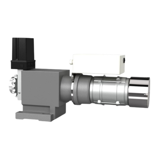
Pos: null /FS_ELEKTROMATEN_Module/Produktübersicht/Produktübersicht_FS_Komponenten_A @ 33\mod_1587022179452_28.docx @ 1646034 @ 1 @ 1 3 Product overview Designation Output shaft: Note the recommendation for the number of teeth on the sprocket and the pitch in the technical data. Spur gear Intermediate flange with centrifugal brake: In the case of fire, the centrifugal brake regulates the speed that the door uses to close. -
Page 7: Storing
Pos: null /FS_ELEKTROMATEN_Module/Lagern/Lagern _ELEKTROMATEN @ 60\mod_1597916702984_28.docx @ 1698026 @ 1 @ 1 4 Storing Store the product in the original packaging. Ensure the following environmental conditions for storage: Closed, dry, dark and vibration-free rooms Temperatures between +5 °C and +40 °C ... -
Page 8: Mechanical Installation
Pos: null /FS_ELEKTROMATEN_Module/Mechanische Montage/Allgemeine Sicherheitshinweise/FS_MechMontage_allgSicherheitshinweise @ 60\mod_1598341728650_28.docx @ 1698954 @ 12 @ 1 6 Mechanical installation General safety information WARNING Danger to life from electric shock! Working on the mechanics may damage electrical lines or components. Danger to life or risk of severe injury from electric current. -
Page 9: Mounting
Pos: null /FS_ELEKTROMATEN_Module/Mechanische Montage/Befestigung/FS_MechMontage_Befestigung_BEF8_AGTFS050 @ 60\mod_1598358812958_28.docx @ 1699266 @ 2 @ 1 Mounting Only use the fastening points shown for mounting the product. Alternative mounting options for separately available accessories are not described here. Use the mounting instructions of the accessories for this purpose. Pos: null /BA_Module_Manuell/Allgemeine_Module/BA_Seitenumbruch @ 29\mod_1567592807787_0.docx @ 1515778 @ @ 1... -
Page 10: Connection Elements
Pos: null /FS_ELEKTROMATEN_Module/Mechanische Montage/Verbindungselemente/FS_MechMontage_Verbindungselemente @ 60\mod_1598356251599_28.docx @ 1699116 @ 2 @ 1 Connection elements WARNING Danger to life from falling parts and uncontrolled movements. The permissible loads on structures, walls, fastenings, connection and transmission elements must not be exceeded, even with maximum holding or locking torques. Please note the technical data of the drive unit. -
Page 11: Work Steps
Work steps WARNING Danger to life from incorrectly installed transmission elements A chain with too little or too much tension may skip or break. As a result, parts of the door structure may become loose and drop. The drive unit or door construction may also suffer damage. ... - Page 12 Tighten the fastening screw of the sprocket. Tension the chain. The slack side (Ⓐ) must not exceed the height of a chain link (Ⓑ). We recommend using a chain tensioner. From an angle of 60°, a chain tensioner is required in the slack side.
-
Page 13: Electrical Installation
Pos: null /FS_ELEKTROMATEN_Module/Elektrische Montage durchführen/Allgemeine Sicherheitshinweise/ELEK-Montage_ELEKTROMATEN-FS_AllgSicherheitshinweise @ 60\mod_1597921777837_28.docx @ 1698708 @ 12 @ 1 7 Electrical installation General information WARNING Danger to life from electric shock! Improper wiring may result in severe or fatal injury from electrical current. Allow only competent people to carry out the work. ... -
Page 14: Attaching The Connection Cables
Pos: null /FS_ELEKTROMATEN_Module/Elektrische Montage durchführen/Verbindungsleitungen anschließen/FS_ElekMontage_Verbinden_Motorstecker @ 60\mod_1598362352275_28.docx @ 1699344 @ 2 @ 1 Attaching the connection cables Remove the limit switch cover. Plug in the motor connector. Pos: null /FS_ELEKTROMATEN_Module/Elektrische Montage durchführen/Verbindungsleitungen anschließen/FS_ElekMontage_Verbinden_Endschalterstecker_NES @ 60\mod_1599822703326_28.docx @ 1701678 @ @ 1 ... -
Page 15: Mechanical Limit Switch - Function
If the movement direction of the drive unit does not correspond to the movement command, you can change the rotating direction. If you use a GfA door control, change the output rotating direction by using the programming. Follow the instructions for the door control. Otherwise change the output rotating direction as explained below. - Page 16 Disconnect all cables from the power supply. Swap L1 and L2 in the supply line. Then switch the voltage back on. Setting the final limit position OPEN Remove the limit switch cover of the drive unit. ...
- Page 17 The final limit position OPEN can be corrected by fine adjustment. Check the door position after a correction. Checking and correcting the emergency limit switch OPEN Setting S3 will automatically preset the emergency limit switch S1. Check whether the preset distance is sufficient.
-
Page 18: Motor Connection
Pos: null /BA_Module/BA_MA Motoranschluss/BAMA010027_M002 @ 72\mod_1645178331047_28.docx @ 1816174 @ 1 @ 1 8 Motor connection Motor BAMA010027 _ Z 001 X13 Motor plug X14 Brake plug Universal brake V1 W1 bl / bu rt / rd Pos: null /BA_Module/BA_NA Endschalteranschluss/BANA001002_M002 @ 54\mod_1593499424091_28.docx @ 1680136 @ 1 @ 1 9 Limit switch connection Thermal contact BANA001002_Z001... -
Page 19: Universal Brake
Pos: null /FS_ELEKTROMATEN_Module/Bremsen/Universalbremse/FS_ElekMontage_Universalbremse_Teil1_Stromzufuhr_allgemein @ 60\mod_1599563938891_28.docx @ 1700841 @ 1 @ 1 Universal brake In the case of a fire, the universal brake opens and the door closes. For the duration of the assembly of the door, the universal brake can be switched to the assembly operating mode. - Page 20 Turn the screw into the centre hole of the guide rail as far as it will go. The guide rail lifts out of the groove. The assembly mode has been set. The braking force is applied when no current is present. Setting the fire-protection mode ...
-
Page 21: Maintenance
Pos: null /BA_Module/BA_WA Abschluss Inbetriebnahme/ Wartung/BAWA000126_M001 @ 77\mod_1651657581266_28.docx @ 1839106 @ 1 @ 1 11 Maintenance WARNING Danger to life from electric shock Improper wiring may result in severe or fatal injury from electrical current. Allow only competent people to carry out the work. ... -
Page 22: Checklist For Fault Correction
In the case of a fault, follow the instructions shown on the door control. Find damage to the door mechanism or door leaf first. The following only mentions faults on the drive unit. When contacting GfA Service, have the serial number of the drive unit ready (see the 11-digit number next to "ID"... -
Page 23: Disposal
Dispose of old devices properly according to local legal regulations. Return old devices to the return and collection systems available. You can also return GfA products free of charge. Please apply enough postage to the package and mark it as "old devices". -
Page 24: Declaration Of Incorporation / Declaration Of Conformity
EMV Directive 2014/30/EU within the meaning of the RoHS Directive 2011/65/EU The following requirements from Appendix I of GfA ELEKTROMATEN GmbH & Co. KG the Machinery Directive 2006/42/EC are met: declare under our sole responsibility that the 1.1.2, 1.1.3, 1.1.5, 1.2.2, 1.2.3, 1.2.6, 1.3.2,...
Need help?
Do you have a question about the ELEKTROMAT FS 50.20-40,00 and is the answer not in the manual?
Questions and answers