Table of Contents
Advertisement
Quick Links
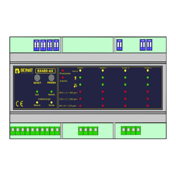
Control Unit from 1 to 4 Conventional sensors BX480-AX
With
program
Through the connection of 4 remote sensors, the BX480-AX control unit has been designed and built according
to European regulations to detect the presence of toxic and/or explosive gas in a flexible way
A microprocessor is used to create a complete surveillance and control system with maximum flexibility.
Thanks to this and its other features, the BX480-AX is suitable for civil and industrial applications.
The BX480-AX control unit has two danger levels:
1
LEVEL, 1
Pre-Alarm. It's set at 13 % L.E.L/200 ppm.
st
st
2
LEVEL, Main Alarm. It's set at 20% L.E.L./300 ppm.
nd
Other technical features make this control unit extremely versatile and reliable; for example, by using a series
of micro-switches it is possible to:
Select or disable a sensor when not installed or faulty;
Select the gas type to be detected (toxic or explosive);
Choose the relay functioning mode (pulsed or continuous);
Choose deadband exclusion mode
A TEST button checks the efficiency of both the unit and connected probe to ensure total control of the BX480-
AX
Thanks to the Omega-type format, small and large systems can be built by exploiting the modularity of the
DIN rail in the previously set electrical panels.
In addition to the alarm signal light, it is fitted with an internal buzzer.
Important: Assembly / maintenance of the appliance must be carried out by qualified personnel
and in accordance with applicable laws and regulations.
The manufacturer assumes no responsibility for the use of products that have to comply with
particular environmental and / or installation standards.
Important note
Before connecting the equipment, it is recommended that you read the instruction manual
carefully and keep it for future reference. It is also recommended to perform the electrical
connections correctly as per enclosed drawings, observing the instructions and the Standards.
N.B. Refer to the documentation in all cases where the symbol is on the side
Installation
and user guide
maintenance
INSTALL IN SAFE
AREA, NO
ATEX
CERTIFIED
II (2)G EN 60079-29-1
FTZÚ 23 ATEX 0078X
EN 50270:2015 - EN 50271:2018
EN 60079-29-1:2016+A1:2022+A11:2022
Rev.1
0477
Advertisement
Table of Contents

Related Manuals for BEINAT BX480-AX


Summary of Contents for BEINAT BX480-AX
- Page 1 Through the connection of 4 remote sensors, the BX480-AX control unit has been designed and built according to European regulations to detect the presence of toxic and/or explosive gas in a flexible way A microprocessor is used to create a complete surveillance and control system with maximum flexibility.
- Page 2 When doing the electrical connections, follow the drawing closely. Any use of the unit for purposes other than the intended one is considered improper, and as a result of which BEINAT S.r.l. therefore disclaims any responsibility for possible damages caused to people, animals or objects.
-
Page 3: Maintenance
Main Compatible Sensors Probe Sensor Degree Suitable for Range Output Precis. Calibration Relay Protec. Zone Detected Working Automatic SG500 C a t a l y t i c I P 3 0 Domestic Use C H 4 - L P G 0÷100% LEL 4÷20 mA ±5 %... - Page 4 When this LED is blinking, the BX480-AX is not able to detect gas. 2) BATTERY LED. This LED lights up when the BX480-AX is powered by the battery in the absence of mains and flashes when the battery voltage is less than 10.8 V.
- Page 5 5) RESET BUTTON A "RESET" button is provided to allow the user to cancel the events that occurred and are contained in the memory by an intentional manual reset. 6) TEST BUTTON Pressing the "TEST" button, it is possible to perform a functional test for the "pre-alarm" relay and the "general alarm"...
-
Page 6: Electrical Connection
{c} OPERATING INSTALLATION INSTRUCTIONS WARNING! The installation parameters modification must be performed by qualified personnel Be sure to disconnect the controller from the power supply before making changes to the connections ELECTRICAL CONNECTION PH N Power supply Fault Pre-Alarm Main Alarm 110/230 VAC The signal terminal block (previous figure) is composed as follows: - Terminals 1, 2 and 3:... -
Page 7: Relay Settings
Switch 1 – Selection of the positive safety Position ON: the positive safety function is enabled. The relay is energized after the warm up phase and turns off when the BX480-AX is main alarm Position OFF: the positive safety function is disabled. - Page 8 {d} OPERATIONAL LIMITATION 01. This device can be set for explosive and toxic gases 02. For transverse sensitivities refer to the remote sensor user manual. 03. Response time T90: 1 second * 04. Temperature operating range: -10° C ÷ + 60° C 05.
-
Page 9: H} Troubleshooting
{h} TROUBLESHOOTING Problem. If the error LED lights up, the system reports an error status. Possible cause: The input current loop is broken or the transmitter is not powered. Solution: Check the connections between the transmitter and the control unit for interruptions. Check with a multimeter the presence of a voltage around 12 VDC between the "+ V"... -
Page 10: Electrical Connections
{q} MARKING Example of a label {r} INSTALLATION EXAMPLES ELECTRICAL CONNECTIONS WARNING. Before connecting to the mains power, ensure the voltage is correct. Carefully follow the instructions and the connections according to Regulations in force, keeping in mind that the signal cables should be laid separate from the power cables. - Page 11 1°Threshold Solenoid valve NC If a 12Vdc solenoid valve is connected to BX480-AX and it does not work well. Direct connection of 12VDC solenoid valves or sirens to BX480-AX is not possible. An external power unit must always be used. BX480-AX gives a max current of 50mA Control unit power supply and connection of one solenoid valve with sirens to 12 VDC trough an alternative source and recharge battery.
- Page 12 If a 12VDC solenoid valve is connected to BX480-AX and it does not work well. Direct connection of 12VDC solenoid valves or sirens to the BX480-AX is not possible. An external power unit must always be used. The BX480-AX gives a max current of 50mA Connections to Positive Safety disabled and an external power supply for valve control and siren 12VDC.
- Page 13 Control unit installation and positioning The BX480-AX control unit belongs to group II and must be installed in a safe area; Outside the ATEX zone, however, not in boiler rooms or engine room. The control unit must be accessible and visible to the user.
- Page 14 Check that the 230V mains power is correctly connected. If powered by the battery, check that the 12Vdc power is correctly connected. If the Fault LED lights up. Check that the connecting cables from the BX480-AX to the probes are intact, that the probes are properly powered, and that the signal cable is correctly connected. WARNING.
-
Page 15: Reset Test
Plant maintenance To enable maintenance mode based on regulations, a manual command must be performed. Follow the instructions below. To proceed with the insertion of maintenance it is necessary: Identify two electrical contacts, shown here with two red parallel bars As you can see, make a short circuit with a screwdriver or other, Here on the side marked by two red parallels... - Page 16 Dealer stamp Purchase date: Serial number: Beinat S.r.l. following the purpose of improving its products, reserves the right to change the technical, aesthetic and functional characteristics at any time and without giving any notice. BEINAT S.r.l. Via Fatebenefratelli 122/C 10077, S. Maurizio C/se (TO) - ITALY Tel.
Need help?
Do you have a question about the BX480-AX and is the answer not in the manual?
Questions and answers