Mopec Maestro MG1000 Series Installation, Service And User Instructions Manual
Hide thumbs
Also See for Maestro MG1000 Series:

Related Manuals for Mopec Maestro MG1000 Series


Summary of Contents for Mopec Maestro MG1000 Series
- Page 1 Installation, Service, and User Instructions Grossing Station / MB1000 / MG1000 series Installation Service User Manual Maestro series MB1000-MAN Rev.4...
- Page 2 Coordinator,” at the address below. Mopec 800 Tech Row, Madison Heights, MI 48071 Phone: 1-800-362-8491 email: customerservice@mopec.com TRADEMARKS Is a registered trademark of Mopec Ensemble Pegboardª Is a registered trademark of Mopec Is a registered trademark of Mopec Owner’s Record Model No.: __________________________________ Serial No.:...
-
Page 3: Table Of Contents
Table of Contents PREFACE ............................7 1.1 ..Description of the User ........................7 1.2 ..Notations Used in This Manual ....................... 7 1.3 ..Models covered in this Manual M(xxxxxxx) ..................7 1.4 ..Explanation of Safety Warnings ...................... 8 1.5 . - Page 4 3.3.2 S torage on a skid ............................17 3.4 ..Disposal and Recycling ........................18 3.4.1 S tainless Steel ............................18 3.4.2 F errous Steel .............................. 18 3.4.3 A luminum ..............................18 3.4.4 P lastic ................................. 18 3.4.5 E lectronics ..............................18 Quick Start Guide ..........................
- Page 5 6.1.5 D ate and Time Adjustment ........................32 6.1.6 T imers Button ............................32 6.1.7 F ormalin Tank level Button ........................32 6.1.8 A larm Settings Button ..........................34 6.1.9 A larms Button ............................35 6.1.10 User Manual Button ..........................36 6.1.11 Calculator Button ..........................
- Page 6 7.3 ..Mopec Service ..........................51 TROUBLESHOOTING AND REPAIR ....................52 8.1 ..How to Identify and Solve Problems ....................52 8.2 ..How to Repair Product Components ..................... 56 8.2.1 E lectrical Panel Service ..........................56 8.2.2 L ighting/Power Supply Panel Service ......................57 8.2.3...
-
Page 7: Preface
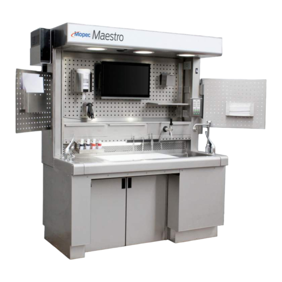
1 PREFACE 1.1 Description of the User The Mopec Maestro is a Pathology Workstation and is available in several different sizes, elevating and non-elevating, with over 30 modification options, and a growing inventory of workstation accessories, the Mopec Maestro is built to be customizable to your laboratory needs and individual preferences. -
Page 8: Explanation Of Safety Warnings
1.5.1 Internet The latest version of the documentation is available at the following address: http://www.mopec.com 1.5.2 Ordering Documentation Documentation, user instructions, and technical information can be ordered by calling Mopec at 800-362-8491. Installation Service User Manual Maestro series MB1000-MAN Rev.4... -
Page 9: Documentation Feedback
1.5.3 Documentation Feedback If you are reading Mopec product documentation on the internet, any comments can be submitted on the support website. Comments can also be sent to customerservice@mopec.com We appreciate your comments. Installation Service User Manual Maestro series MB1000-MAN Rev.4... -
Page 10: Description Of The Product
2.1 Purpose of the Product The Mopec Maestro™ is the most advanced pathology workstation on the market today and is designed with the special needs of the user in mind. Careful consideration is given to the functional requirements and workflow patterns, as well as the need for maximum space utilization and sanitation. -
Page 11: Product Elements
EN 61010-1:2010 Safety requirements for electrical equipment for measurement control and laboratory use. ¥ 2.6 Product elements The Maestro is constructed as one assembled workstation with 3 main elements in its construction: A. Base The base constitutes the framework, cabinetry, and elevation system and control. It also contains rough-in utility connections for electrical, plumbing &... -
Page 12: Warranty Statement
(if installation is provided by Mopec), the defective or nonconforming Product or Part thereof will be repaired or (at Mopec's option) replaced free of charge, FCA Mopec's dock. All warranty claims must be in writing and received by Mopec within the warranty period. The warranty is not transferable (other than to customers of Mopec’s authorized Distributors), and will not apply unless the Equipment has been properly installed, maintained, and operated in accordance with all instructions;... -
Page 13: Installation
¥ Check that the top of the crate has not sustained damage or has evidence of being placed upside down. ¥ Take photographs of any damage and contact Mopec or your private freight carrier if applicable. ¥ 3.1.2 Uncrating Contents: Remove the top boards from the crate. -
Page 14: Placing Unit Into Position
3.1.5 Placing unit into position Before you unload the equipment check that the utilities have been prepared in accordance with the Mopec ¥ rough-in drawing for your model workstation. Check the floor condition is clean dry and as level as possible. Masonite boards can be used to protect ¥... -
Page 15: Plumbing Connection
3.1.7 Plumbing Connection; Do not use a powered screw gun to remove or install the screws. A screw gun can damage the PEM nut in the sheet metal. Plumbing connections are to be made by a licensed professional plumber. ¥ The inner knee space skirting will have to be removed to access the connections for electrical and plumbing. -
Page 16: Entilation Connection (In-House Ventilation)
HOT and COLD water lines should be connected directly to the factory-supplied water strainers. Especially ¥ in new construction, these strainers are your only protection from site debris damaging seals and valves in your new workstation. Water strainers supplied have a ½” NPT female thread. Plan final connections to HOT and COLD water lines ¥... -
Page 17: Recirculating Ventilation (If Equipped)
3.1.9 Recirculating Ventilation (if equipped) No external ductwork is connected if the unit is equipped with recirculating ventilation unit. ¥ Recirculation filters are loaded into the top of the unit. Check that all packaging and wrap are removed from ¥ filters before use. -
Page 18: Disposal And Recycling
3.4 Disposal and Recycling Disposal of the unit is ultimately up to local codes and guidelines. The following section breaks down the materials of construction for recycling purposes. 3.4.1 Stainless Steel The Hood is made entirely of 304 stainless steel. Remove all electronics and recycle them appropriately. ¥... -
Page 19: Quick Start Guide
4 Quick Start Guide 4.1 Startup The following section explains how to start the Maestro and some of its standard functions. CAUTION The unit must be installed per factory recommendations in section 3.1 of the user manual. 4.1.1 Powering On The unit is powered on by the main power switch located on the sink side column in the Hood section. -
Page 20: Elevation
a. Actions Screen b. Lights screen 4.1.3 Elevation The elevation of the unit is adjustable from the Elevation (</>) button located on the front corner of the sink ¥ The unit has 12” (30.48cm) of elevation, select the best position for sitting or standing. Stand clear and check for obstructions surrounding (and under) the Maestro when raising and lowering the unit. -
Page 21: Powering Down
4.2 Powering down 4.2.1 Shut down Use the main power switch to shut down the unit. This will power down the internal circuitry including the ¥ power outlets on the hood backsplash. Most units are connected to central facility-powered HVAC ventilation and are controlled separately. ¥... -
Page 22: Factory Options & Accessories
Factory Options & Accessories 5.1 Standard Features 5.1.1 The Maestro is equipped with the following standard features. Dimensions: 60" L x 32" W x 75" H & 87” elevated (1.5m L x 0.8m W x 1.9m H elevated 2.2) ¥ Stainless steel construction ¥... -
Page 23: Customization (Cust)
MB1039-054 MAESTRO, RECIRCULATING BOX, 54IN (1.3m) UNITS ¥ MB1039-066 MAESTRO, RECIRCULATING BOX, 66IN (1.6m) UNITS ¥ MB1039-072 MAESTRO, RECIRCULATING BOX, 72IN (1.8m) UNITS ¥ MB1039-084 MAESTRO, RECIRCULATING BOX, 84IN (2.1m) UNITS ¥ MB1039-096 MAESTRO, RECIRCULATING BOX, 96IN (2.4m)UNITS ¥ MB1040 MAESTRO, FORMALIN DISPENSE ¥... -
Page 24: New Options
5.2.3 New Options As New factory-built options become available they will be posted on www.mopec.com ¥ 5.3 Accessories Accessories are features and tools that can be added to the Maestro at any time by the user or supporting staff. 5.3.1 Standard Accessories shipped with your Maestro. -
Page 25: Customization (Cust)
AX110 MAESTRO, RECIRCULATING TO IN-HOUSE KIT ¥ AX111 MAESTRO LITE, EXHAUST DAMPING KIT, 8IN DUCT ¥ AX112 MAESTRO, VIRTUS CAMERA HOOD ¥ AX113 MOPEC CORNER DOLLY, SET OF 4 ¥ AX114 MAESTRO, MILESTONE CAMERA ¥ AX115 MAESTRO, HITCH MOUNT, KEYBOARD ¥... -
Page 26: New Accessories
5.3.4 New Accessories New Maestro Accessories are developed every day! To make a suggestion for a new accessory or to check ¥ on our latest go to www.mopec.com for more information. Installation Service User Manual Maestro series MB1000-MAN Rev.4... -
Page 27: Operation/Use
Understanding the Maestro Operational Interface Mopec designed the Maestro to be highly customizable in its construction to meet all types of process flows and procedural preferences in the pathology lab. The touchscreen display allows for variable user interface controls to support the many configurations available on the Maestro. -
Page 28: Lights Button
The Maestro’s Actions screen is the main page when the unit is powered on. ¥ The Maestro’s Actions page is the home screen where the user can quickly navigate to any feature installed on the grossing station. The Actions page is set up in a manner that categorizes the main features into easily accessible buttons. -
Page 29: Entilation Button
Front Air System (FAS) On and Off toggles. If the units weren’t configured with one or all these features, it will display “Not Installed”. The patented FAS system is a key safety feature on Mopec laboratory equipment. The principle of operation is simple and safe. - Page 30 A flow sensor is a standard feature on all Maestros. The flow sensor is integrated into the Maestro hood to provide a method to alarm if airflow in the facility has been impeded or adjusted below a set threshold. This setting is only intended to provide an alert.
- Page 31 The Recirculation option is intended for facilities that do not have available HVAC exhaust flow available for temporary use or in limited-use environments. The backdraft air is pulled through the hood by variable-speed blowers and cycled through filters in an effort to remove particulates and fumes before exhausting back into the room at the top of the unit.
-
Page 32: Date And Time Adjustment
6.1.5 Date and Time Adjustment To change the Date and Time you must be logged in as a manager (reference 6.1.4) and. Once logged in press and hold either the date or time on the display. A popup will come that will allow you to make the indicated change. - Page 33 the formalin level observation screen. This screen will also show when the dispense pump button is pressed. This screen can aid users by visually seeing the amount of formalin in the dispensing system. The Formalin Dispense system on a Maestro utilizes a siphon hose and a transfer pump to fill up a reservoir tank located in the hood of the unit. This enables a very controllable gravity-fed dispense from a simple lever pull on the spigot.
-
Page 34: Alarm Settings Button
To start pumping simply hold down the green Dispense Pump button located just inside the knee panel. The ¥ system is equipped with level sensors and will turn off the pump when full. The user can visually see if the tank is Low, Partially Full, or Full by viewing the tank Level Screen. -
Page 35: Alarms Button
6.1.9 Alarms Button Once the operator selects the Alarms button on the home page you will be presented with a screen showing all the possible alarm conditions. This screen helps notify the user of what function has an active alarm. Near each alarm feature title, there is a gray notification light when the function doesn’t have an active alarm. -
Page 36: User Manual Button
6.1.10 User Manual Button The User Manual Button takes the users to a screen with a 3D barcode with the Mopec logo. If users scan the barcode with a smartphone, it will provide a link to a web address having the latest Maestro product manual. This can be a great feature to look up how a specific feature functions. -
Page 37: Calculator Button
The Factory login is only to be used at the Mopec manufacturing facility to configure units during the manufacturing process or by Mopec service technicians in the field. Below are the login credentials for the Operator and the Manager. Installation Service User Manual Maestro series MB1000-MAN Rev.4... -
Page 38: How To Use Maestro Standard Features & Options
Credentials and Passwords. Operator, Password = 000000 Manager, Password = 810810 6.2 How to Use Maestro Standard Features & Options 6.2.1 Lighting (standard) The Maestro has recessed LED lights integrated into the hood, and a few supplemental light options are available. The overhead LED dimmer is adjustable by touching the Lights button on the action screen. -
Page 39: Faucet Controls (Standard)
CAUTION Risk of Pinching or Crushing Hazard. Ensure that hands, fingers, and other body parts are clear of moving parts and mechanisms during opera}on and adjustment of the eleva}ng worksta}on. Failure to do so may result in serious injury or amputa}on. The Maestro skir}ng is designed to limit the number of pinch points. -
Page 40: Infrared Faucet Control "Hands-Free" Option
Foot Pedal Hot/Cold Mixing Valve The foot pedal is mounted to a floor plate that can be positioned within reach by the user. ¥ A single tap of the pedal turns the hot/cold mixed water on. ¥ Tap the pedal a second time to turn it off. ¥... -
Page 41: End Rinse Option
The Syphon Hose is intended to be connected to your formalin supply container (cut factory zip tie to uncoil ¥ hose). Mopec cubitainers utilize a quick disconnect. Insert the connector and pull to make sure it is latched. If you are pumping from a formalin barrel remove the supplied quick disconnect fitting and directly insert the end of the siphon hose into the barrel. -
Page 42: Formalin Collection Option
An empty system will typically transfer 5 gallons when filling. An alarm will alert users when the tank becomes low. ¥ Mopec recommends refilling the dispensing tank after usage to reduce the crystallization buildup on the float ¥ level sensor. -
Page 43: Integrated Camera System Options
The drain hose is supplied long enough to allow the collection dolly to be pulled out from under the knee space ¥ before disconnecting. This will create a small fluid trap if left at the factory cut length on the collection line. o If your preference is to eliminate the fluid trap simply trim the line back short enough that the fluid drains completely into the carboy. -
Page 44: Bms (Building Management System) Connection
6.2.11 BMS (Building Management System) Connection Mopec BMS (Building Management System) connection, option MB1022, is a simple output signal intended to be connected to a hospital remote management system. The function is a dry contact relay output that is triggered by an alert condition on the Maestro. - Page 45 o Turn off the facility water supply to the unit if further plumbing issues are detected. Air Flow Alert ¥ o Check for facility flow, and alert laboratory management. Installation Service User Manual Maestro series MB1000-MAN Rev.4...
-
Page 46: Maintenance
Depending on your model the recirculating unit may have 3-6 filters. ¥ Use latex or nitrile gloves when removing the filters. All replacement filters will use a Mopec BF035 Potassium Permanganate Filter in each slot. Install the new filters with the white side down and black mesh up top. -
Page 47: Health Hazard Information & Disposing Of Filters
To determine if the potassium permanganate has been exhausted remove a pellet and cut it in half. ¥ With the pellet on a white paper towel add a few drops of water to the pellet. The water running off the ¥... -
Page 48: Resetting The Main Gfci
Continue to hold for another 3 seconds and then release both buttons. ¥ Adjust the unit up and down and confirm the unit has remained level. Repeat the reset procedure multiple ¥ times if you suspect it has not fully leveled out. Verifying the unit is level at all heights confirms the unit is elevating properly. -
Page 49: Resetting The Auxiliary Gfci
If the GFCI fails, there may still be a ground fault in the system or the GFCI unit may need to be replaced. See ¥ the section on Troubleshooting (8.0) or call Mopec Service (7.3) 7.1.6 Resetting the Auxiliary GFCI The Maestro is equipped with an auxiliary 15amp GFCI power outlet for uninterrupted supply on a computer system or other auxiliary devices plugged into the side panel. -
Page 50: Stainless Care And Maintenance
o If your process must use chlorine bleach it must not exceed 10% and must be rinsed immediately after disinfection to avoid damage to the metal. 7.2.2 Stainless Care and Maintenance To maintain your stainless steel product, follow these steps: Rinse the surfaces with water frequently. -
Page 51: Fingerprints And Solvent Cleaning
It is best to follow with a warm water rinse. 7.3 Mopec Service PLEASE have the following information available BEFORE you call from your station ID tag or original order or quote. -
Page 52: Troubleshooting And Repair
8 TROUBLESHOOTING AND REPAIR 8.1 How to Identify and Solve Problems WARNING: The troubleshooting section is for reference only. Repairs are be made by licenced electrician or plumbing professional and shall follow proper facility safety protocols and a Lock out tag out Procedure. Error / Issue / Failure Cause Solution... - Page 53 Water Fixture Failures Facility water turned “OFF” Turn “ON” facility water supply Mixing valve (pressure/temp Turn mixing valve “ON” control turned “OFF” Check Y Strainers for debris. Water system plugged Check for kinked supply lines. Check backflow prevention devices (REF 8.2.5) My station’s faucets do not 1.
- Page 54 Check in lower skirting for interference Mixing valve “OFF” Turn mixing valve “ON” Gate valve for end rinse Turn gate valve “ON” “OFF” My hand rinse or end rinse are Check Y Strainers for debris not working Check for kinked supply lines Water system plugged Check backflow prevention devices (REF 8.2.5) Clean end rinse orifice with small pick to dislodge...
- Page 55 Adjust brightness to user preference in Light menu Brightness set too dim. on the touch screen Lights are too dim or bright Check connections in hood at driver. LED driver issue Check driver output. Replace driver GARBAGE DISPOSAL turn off facility breaker and remove jam (REF Disposal is jammed 8.2.3) Facility breaker is tripped...
-
Page 56: How To Repair Product Components
Formalin Dispensing Leak alarm is There is a formalin leak or Repair leak & clean sensor of fluid or replace faulty present (sensor #1, inside station, sensor is faulty sensor beneath formalin storage tank) FORMALIN COLLECTION SYSTEM Formalin collection Empty formalin Jug/Carboy Jug/Carboy is full Plug float switch into station. -
Page 57: Lighting/Power Supply Panel Service
It is important to leave 10 inches of clearance to access this panel as it houses the PLC, HMI, Electrical DIN rail, and relays that may need service. 8.2.2 Lighting/Power Supply Panel Service The top of the hood houses the DC power supply and LED lighting components. To service components in the hood, use a Phillips screwdriver to remove the top cover. -
Page 58: Garbage Disposal Jams
8.2.3 Garbage Disposal Jams The most common disposal failure is a Jam. Turn off the power to the station and check the disposal with a piece of wood, like a broom handle. Attempt to rotate the rotor both clockwise and counterclockwise to confirm the motor is not locked up. - Page 59 Disconnect the power cord, loosen the hose clamp, and disconnect the flexible drain line. Lastly, remove the lock ring at the disposal. Reference Moen GX50C specification for more information. MB1021 Optioned Models use a 1 HP disposal Mopec part PP0944 – (Moen GX100C) ¥...
-
Page 60: Faucet, Hand Spray & End Rinse Service Panel
Check the airline connection to the switch has not become dislodged or completely disconnected due to ¥ shipping and handling or service in the area. The airline is located on the back of the unit behind the sink. The foot pedal is also operated via an airline take note of which one you are inspecting. 8.2.5 Faucet, Hand Spray &... -
Page 61: Backflow Prevention And Service
8.2.6 Backflow prevention and Service The Maestro utilizes two types of products for backflow prevention. Atmospheric Vacuum Breaker equipped faucets – Chicago Faucets #GN8BVBJKABCP ¥ 8" (20cm) rigid/swing gooseneck spout with atmospheric vacuum breaker | Chicago Faucets In-line Dual Check valve backflow preventer. Used on hand sprays, end rinses & water injected disposal units. ¥... -
Page 62: Documentation
9 Documentation 9.1 Sample Rough in Drawing Installation Service User Manual Maestro series MB1000-MAN Rev.4... -
Page 63: Electrical Diagrams
9.2 Electrical diagrams Installation Service User Manual Maestro series MB1000-MAN Rev.4... - Page 64 Installation Service User Manual Maestro series MB1000-MAN Rev.4...
-
Page 65: Plumbing Diagrams
9.3 Plumbing diagrams Installation Service User Manual Maestro series MB1000-MAN Rev.4... - Page 66 Installation Service User Manual Maestro series MB1000-MAN Rev.4...
-
Page 67: Hvac / Ventilation Diagram
9.4 HVAC / Ventilation diagram The following is a graphic representation of airflow on an in-house ventilated Maestro. Installation Service User Manual Maestro series MB1000-MAN Rev.4... -
Page 68: Appendices
Mopec # OEM # Use(s) Collection Carboy PM0141 US plastics #73003 Formalin collection Collection Cap assembly 5850 n/a – custom to Mopec Formalin collection Collection tubing (¾” Vinyl) PP0045 McMaster 5233K71 Formalin collection Disposal ½ HP PP1029 Moen GX50C Garbage disposal... -
Page 69: Consumables
Automation Direct GCX3202- Pump Button, Green PE0770 Formalin dispensing Float Sensor, 6.5” lg. (16.51cm) PE0285 n/a – custom to Mopec Formalin Collection Sensor Float Sensor, 18” lg. (45.72cm) PE0768 n/a – custom to Mopec Formalin dispensing Leak Sensor PE0805 n/a – custom to Mopec Formalin dispensing LED Light fixture, 7”... -
Page 70: Glossary
11 GLOSSARY Term Meaning Maestro Trademarked name of Mopec’s flagship grossing workstation Acronym for the Patented technology, Front Air System, where an extra burst of air is blown across the front of the worksurface to help protect the user from dangerous...
Need help?
Do you have a question about the Maestro MG1000 Series and is the answer not in the manual?
Questions and answers