Table of Contents
Advertisement
Quick Links
Advertisement
Table of Contents

Related Manuals for SIEB & MEYER SD4B


Summary of Contents for SIEB & MEYER SD4B
- Page 1 SIEB & MEYER Drive Amplifier SD4B Hardware Description D-00000374.1 2023-10-04...
- Page 2 SIEB & MEYER Asia Co. Ltd. 5 Fl, No. 578, Sec. 1 Min-Sheng N. Road Kwei-Shan Hsiang Guishan Dist., Taoyuan City 33393 Taiwan Phone: +886 3 311 5560 Fax: +886 3 322 1224 info@sieb-meyer.tw Drive Amplifier SD4B - Hardware Description...
-
Page 3: Table Of Contents
Cables for the Rotor Position Detection............... P2P Button........................X6 – encoder....................... 7.4.1 Encoder Signals......................7.4.2 Hall Sensor RS422....................... 7.4.3 Pulse Encoder 5 V......................36 7.4.4 Incremental Encoder with TTL Signals.................37 X10 – Communication RS232/RS485/CAN............... 7.5.1 RS232 Diagnosis......................38 7.5.2 RS485 Bus........................Drive Amplifier SD4B - Hardware Description... - Page 4 Wiring Example......................8.1.3 Requirements and Standards..................53 8.1.4 Restart Lock Procedure....................54 LED Status Displays............SD4x Drive Messages............10.1 Error Messages......................58 10.2 Messages........................Appendix................64 Exception......................64 Manufacturers......................65 SIEB & MEYER Accessories..................65 B.1.1 Connector Kit..........................Phoenix Contact......................Index..................68 Drive Amplifier SD4B - Hardware Description...
-
Page 5: About This Manual
Indicates a hazardous situation which, if not avoided, may result in property damage. → Follow the instructions in this manual to avoid danger. Technical Symbols Symbol Description LED indicator: LED on LED indicator: LED off LED indicator: LED flashes Drive Amplifier SD4B - Hardware Description... -
Page 6: Abbreviations
SELV safety extra-low voltage SERVO servo control safe failure fraction safety function: Safe Torque Off sensorless vector control UVLO undervoltage-lockout voltage at the common collector VECTOR vector control V/f characteristic curve Drive Amplifier SD4B - Hardware Description... -
Page 7: General Information
General Information General Information This manual describes the drive amplifiers of the series SD4B. Drive amplifiers of the generation SD4x are BDM (basic drive modules) that can be used either as frequency converter or as servo amplifier. The drive amplifiers of the series SD4B allow operation of high-dynamic servo motors as well as asynchronous high-frequency spindles in the low-voltage range. -
Page 8: Safety Instructions
CE conformity of the complete machine or installation. Note If the mechanics or the electronics of the device are modified, the conformity with the EC/EEC directives and thus the label will expire. Drive Amplifier SD4B - Hardware Description... -
Page 9: Working On The Device
2 or equivalent environmental conditions. That means: En- sure to avoid conductive impurities and humidity during the operation. SIEB & MEYER products are not suitable for use in areas exposed to explosion hazards (ATEX zones) without approriate housing. Drive Amplifier SD4B - Hardware Description... -
Page 10: Reasonably Foreseeable Misuse
During design and construction of the machine as well as in the operation manual the machine manufacturer is obliged to give consideration to the intended (appropriate) use of the machine and risks arising from reasonably foreseeable misuse of the machine. Drive Amplifier SD4B - Hardware Description... -
Page 11: Electrical Connection
(only for ma- chine manufacturers). The manufacturer of the system or machine has to meet the re- quirements of the legislation regarding the EMC. Drive Amplifier SD4B - Hardware Description... -
Page 12: Operation
During the operation of an installation with open doors or removed covers, persons may seriously be injured by moving machine parts. → Keep the doors closed during the operation and do not remove cov- ers. Drive Amplifier SD4B - Hardware Description... -
Page 13: Maintenance
SJ/T 11364-2014 (China RoHS 2 on the restriction of the use of hazardous substances in electrical and electronic equipment) SIEB & MEYER products labeled with the symbol above do not exceed the limits of the directive SJ/T 11364-2014 for hazardous substances. Drive Amplifier SD4B - Hardware Description... -
Page 14: Legal Warranty
NOTICE Due diligence of the machine manufacturer → A first programming carried out by SIEB & MEYER does not release the machine manufacturer from his duty to check the programmed values for correctness. Drive Amplifier SD4B - Hardware Description... -
Page 15: Unit Assembly Complying Emc
▶ safety-relevant aspects ▶ extracts from the EMC product standard ▶ possibilities for the connection to different supply system types Availability: ▶ PDF file under www.sieb-meyer.de/downloads.html Drive Amplifier SD4B - Hardware Description... -
Page 16: Drive Amplifier Sd4B
Drive Amplifier SD4B Drive Amplifier SD4B Connection Examples Fig. 1: SD4B connection examples Drive Amplifier SD4B - Hardware Description... -
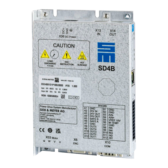
Page 17: Type Plate
Drive Amplifier SD4B Type Plate Fig. 2: Example of type plate SD4B Meaning Explanation Type designation indicates the exact device type (see page IP code Indicates the level of protection of the device against touching or intrusion of solid objects (1st digit) and water ingress (2nd digit) Device version Indicates the version of the hardware;... -
Page 18: Sd4B Type Designation
In addition, the device version indicates the update capability of the internal device soft- ware, e.g. BIOS, FPGA or Firmware. General Technical Data The following data apply to all devices of the series SD4B. Drive Amplifier SD4B - Hardware Description... -
Page 19: Storage And Transport
5 °C to 60 °C (100 % rated current up to max. 40 °C; at higher temperatures the rated cur- rent must be reduced by 1.5 % per 1 C°.) Humidity range 5 % RH to 85 % RH (non-condensing) Drive Amplifier SD4B - Hardware Description... -
Page 20: Current Derating Due To Site Altitude And Temperature
Current Derating Due to Low Speed During phases of a static rotating field or low rotating field frequencies (f ≤ 5 Hz) the power semiconductors of the output stage are subject to higher loads. Drive Amplifier SD4B - Hardware Description... -
Page 21: S6 Duty Type
ISO 8482:1993 compliant analog input Working range ±10 V ▶ differential Max. input voltage ±12 V Resolution 14 Bit Linearity < 0.1 % Offset error < 0.1 % Input impedance 10 kΩ Sampling rate 4 kHz Drive Amplifier SD4B - Hardware Description... -
Page 22: Motor Control
Response time 4 ms OSSD test signals ≥ 2 ms OSSD1 1 ms Tab. 4: Technical data of the interfaces 5.4.7 Motor Control Sampling rate Unit Value Sampling rate commutation 2 × switching frequency Drive Amplifier SD4B - Hardware Description... -
Page 23: Specification Of Real Time Clock
Note A battery change may only be carried out by SIEB & MEYER or a repair shop approved by SIEB & MEYER. Unauthorized opening of the device results in the loss of warranty! Drive Amplifier SD4B - Hardware Description... -
Page 24: 0Sd4Bb1D1Pxxxx
0SD4BB1D1Pxxxx Features: ▶ DC power supply: adjustable from 24 to 80 V ▶ output power up to 980 W ▶ safety circuit (STO) Dimensions and Mounting Fig. 5: Dimensions of SD4B in mm (inch) Drive Amplifier SD4B - Hardware Description... - Page 25 The mounting surface must be able to dissipate a heat output of 25 W at a housing temperature of 60 °C for each device. ▶ With vertical mounting several device can be mounted next to each other without any space in-between. Drive Amplifier SD4B - Hardware Description...
-
Page 26: Technical Data
Rated power, internal ballast resistor 50.0 Pulse energy, internal ballast resistor Device IP code IP 20 Protection class acc. to DIN EN 61800-5-1 Weight 0.525 Primary cooling medium Admissible voltage ripple: max. 10 % Drive Amplifier SD4B - Hardware Description... -
Page 27: Overload Times
Applies to device variant 0SD4BB1D1PxxxL (only (with limited output frequency), not for device variant 0SD4BB1D1PxxxU (with unlimited output frequency). Tab. 7: Electrical data 0SD4BB1D1Pxxxx 6.2.2 Overload Times Load cutoff: Overload cutoff: Fig. 7: Load cutoff 0SD4BB1D1Pxxxx Fig. 8: Overload cutoff 0SD4BB1D1Pxxxx Drive Amplifier SD4B - Hardware Description... -
Page 28: Connectors, Displays And Buttons
X36 DC Power DC power input page 46 X53 Motor Motor output page 47 Note You can order the suitable connector kit for the device variant 0SD4BB1D1Pxxxx at SIEB & MEYER under article number 32299587. Drive Amplifier SD4B - Hardware Description... -
Page 29: Connectors
The contact spring presses the cable against the conducting copper bar. The special spring profile allows direct and tool-free wiring of solid and flexible cables previously as- sembled with ferrule or compressed conductor ends (0.25 mm² or greater). Drive Amplifier SD4B - Hardware Description... -
Page 30: Cable Requirements
The line cross-sections should be selected carefully so that the maximum admissible current is not exceeded at the maximum ambient temperature (see technical data). DIN EN 60204-1 defines the admissible values for the individual line cross-sections which must absolutely be taken into account. Drive Amplifier SD4B - Hardware Description... - Page 31 ISO and AWG/MCM values are shown in the following table. Standardized cross-sections of round conductors: ISO cross-section [mm²] AWG/MCM Value Equivalent cross-section [mm²] 0,205 – 0,324 0,519 0,75 0,82 – – 13,3 Drive Amplifier SD4B - Hardware Description...
-
Page 32: Motor Cable
Use shielded cables for the motor in order to keep interference as low as possible. The cable shield must be connected large-area with 360° shield termination. In addition, the motor cable should be as short as possible to reduce electromagnetic radiation and capacitive currents. Drive Amplifier SD4B - Hardware Description... -
Page 33: Communication Cables
Use shielded lines and shielded D-sub shells for wiring the different measuring systems. Connect the cable shield to both connector shells: At the drive connect the shield to the D-sub shell and at the motor to the shell of the measuring system connector. Drive Amplifier SD4B - Hardware Description... -
Page 34: P2P Button
M1_B+ Track B+ M1_B− Track B− VCC5.3 5.3 V supply voltage M1_AUX+ Pulse IN (5 V) The cable shield is connected to the connector shell. Stud bolt flange: max. tightening torque = 0.7 Nm Drive Amplifier SD4B - Hardware Description... -
Page 35: Encoder Signals
Connectors 7.4.1 Encoder Signals Pulse Pulse Direction Direction Down Down Quadrature Fig. 12: Encoder signals (X6) Drive Amplifier SD4B - Hardware Description... -
Page 36: Hall Sensor Rs422
Fig. 13: Hall sensor RS422 (X6) 7.4.3 Pulse Encoder 5 V Drive Pulse encoder 3.3 V 2.2 k M1/2 AUX+ 74 HC 3.3 V 22 nF VCC5.3 Fig. 14: Pulse encoder 5 V (X6) Drive Amplifier SD4B - Hardware Description... -
Page 37: Incremental Encoder With Ttl Signals
5.3 V supply voltage (power supply for optional operating terminal) RS232_Rx Receive data RS232_Tx Transmit data CAN_L CAN Low Ground RS485_D+ Data+ RS485_D− Data− CAN_H CAN High Ground Stud bolt flange: max. tightening torque = 0.7 Nm Drive Amplifier SD4B - Hardware Description... -
Page 38: Rs232 Diagnosis
These resistors with a value of approximately 560 Ω are usually implemented in the master. The drives do not provide the resistors for this purpose. Drive Amplifier SD4B - Hardware Description... -
Page 39: Can Interface
The limiting value is between 32 and 100 bus nodes depending on the used cable and transmission rate. For further information on the maximum number of bus nodes refer to the document “CAN Physical Layer” by the user organization CiA. Drive Amplifier SD4B - Hardware Description... -
Page 40: X11 - Ethernet 10/100 Mbit
SD4x drives are parameterized, put into op- eration and maintained. Machine hall Drive 1 supervisor drivemaster4 RJ45 patch cable IT infrastructure 100 MBit (corporate LAN) Maintenance Drive 2 SWITCH drivemaster4 Drive n Fernwartung Service drivemaster4 Fig. 20: Ethernet communication (X11) Drive Amplifier SD4B - Hardware Description... -
Page 41: X13/X14 - Fieldbus In/Out
Ethernet, but does not send/re- Green LED 0 ceive Ethernet frames. Activity: The device has established a con- Flickers green nection with Ethernet and sends/receives (load-dependent) Ethernet frames. LED 1 This LED is not used. Drive Amplifier SD4B - Hardware Description... -
Page 42: X15 - Inputs/Outputs / Safety Circuit (Sto)
A5 and pin A6 must be bridged to pin A4. Specification of terminal connections ▶ Conductor cross-section solid/stranded: 0.2 to 1.5 mm² ▶ Connection method: spring-cage connection (handling: see page Related topics Safety Circuit / Restart Lock (STO), page 49 Drive Amplifier SD4B - Hardware Description... -
Page 43: Digital Inputs
Digital Outputs The output driver can operate as low-side driver or as high-side driver. You can set the desired driver type in the software drivemaster4. Fig. 22: Digital outputs (X15) parameterized as low-side driver Drive Amplifier SD4B - Hardware Description... -
Page 44: Analog Input
3.3 k 4,7 nF 10 nF VCC10 B1, B2, B7 Fig. 24: Analog Input (X15) Voltage interface with input voltage range: ±10 V Can also be connected to potentiometer (500 Ω – 5 kΩ) Drive Amplifier SD4B - Hardware Description... -
Page 45: Connecting The Motor Protection
8.1 “Safety Circuit / Restart Lock (STO)”, page 7.8.5.1 Wiring with OSSD OSSD = Output Signal Switching Device Drive OSSD1 SAFE A OSSD2 SAFE B Fig. 26: Safety circuit (STO) - wiring with OSSD Drive Amplifier SD4B - Hardware Description... -
Page 46: Wiring Without Ossd
Connection method: push-in spring connection (handling: see page NOTICE Wiring error → To prevent wiring errors and subsequent damage to the device you must always wire all pins (incl. pin 2 / DC−) with adequate conductor cross-section. Drive Amplifier SD4B - Hardware Description... -
Page 47: Connecting The Voltage Supply
Motor phase W Protective conductor Specification of terminal connections ▶ Conductor cross-section solid: 1 to 1.5 mm² ▶ Conductor cross-section stranded: 1 to 2.5 mm² ▶ Connection method: push-in spring connection (handling: see page Drive Amplifier SD4B - Hardware Description... -
Page 48: Connecting The Motor Phases
→ Consider the following with regard to shielding: Always use shielded motor cables. Drive Amplifier SD4B - Hardware Description... -
Page 49: Functional Safety
The advantage of this circuit is that a single drive can be locked safely in an installation with several drives, while the other drives remain in operation. Besides, a drive can be locked without having to recharge the DC link before a restart. Drive Amplifier SD4B - Hardware Description... -
Page 50: Functional Description Of The Restart Lock
4 ms. The restart lock must only be controlled when ▶ the drive is at a secure standstill (stop category 2), ▶ the higher-ranking control has deactivated the drive module, ▶ (reference speed value 0) Drive Amplifier SD4B - Hardware Description... -
Page 51: Wiring Example
(according to stop func- tion category 0+1) according to the safety requirements of SIL 3 (DIN EN ISO 13849-1). With this circuit you can connect several emergency stop devices in series, which are permanently monitored. Drive Amplifier SD4B - Hardware Description... - Page 52 IEC 60249 covered by a nonaging protective coat of lacquer ac- cording to IEC 60664-3:2003-09 have been used. The conformity of standard have been tested and approved by the TÜV-Nord CERT. Drive Amplifier SD4B - Hardware Description...
-
Page 53: Requirements And Standards
When connected appropriately, the safety concept K2 does not supply any share of dan- gerous, undetected errors in the safety chain for the function STO. Thus the stop function 0+1 according to DIN EN 60204-1 is realized. Drive Amplifier SD4B - Hardware Description... -
Page 54: Restart Lock Procedure
The drive amplifier switches to the status “fault”. The drive am- plifier can apply torque to a connected motor as soon as the fault is acknowledged, the safety function STO is deactivated and the power output stage is switched on. Drive Amplifier SD4B - Hardware Description... - Page 55 Functional Safety Drive Amplifier SD4B - Hardware Description...
-
Page 56: Led Status Displays
LED COM 0 (LED 5) indicates the system status and COM 1 (LED 6) possible error states. In the following you find the LED status descriptions depending on the fieldbus protocol. Drive Amplifier SD4B - Hardware Description... - Page 57 The slave module is in the Ready to Operate status. 3 × Green fl. The slave module is in the Operational status. Green LED 6 No error The slave module has detected an error. Drive Amplifier SD4B - Hardware Description...
-
Page 58: Sd4X Drive Messages
Braking Safety error I 0xFF20 Safety error II 0xFF30 STO with active output stage 0xFF40 Immediate switch-off Reserved Ambient temperature too high 0x4110 Braking 20-1 Ambient temperature to high - CPU 0x4111 Braking Reserved Drive Amplifier SD4B - Hardware Description... - Page 59 Feedback 1 - Error 12 0x732C Coast to standstill or braking Yes 34-13 Feedback 1 - Error 13 0x732D Coast to standstill or braking Yes 34-14 Feedback 1 - Error 14 0x732E Coast to standstill or braking Yes Drive Amplifier SD4B - Hardware Description...
- Page 60 Output stage - Overtemperature phase U 0x4211 Immediate switch-off 55-2 Output stage - Overtemperature phase V 0x4212 Immediate switch-off 55-3 Output stage - Overtemperature phase W 0x4213 Immediate switch-off Output stage - Short to ground 0x2330 Immediate switch-off Drive Amplifier SD4B - Hardware Description...
- Page 61 CPU - Memory error - Unstacking error by ARM MPU 0x618E Coast to standstill 64-15 CPU - Memory error - Instr fetch from protected location 0x618F Coast to standstill Tab. 9: Error messages of SD4x series Drive Amplifier SD4B - Hardware Description...
-
Page 62: Messages
MSG_SB33_WARN_MOTOR_TEMP Motor - Temperature (For temperature sensors KTY and PT1000 only) MSG_SB34_MOTOR_COASTED_TO_STANDSTILL Motor has coasted to a standstill MSG_SB35_MOTOR_BRAKE_ACTIVE Motor holding brake is active MSG_SB36_WARN_AMBIENT_TEMP Ambient temperature too high MSG_SB37_WARN_MOTOR_TEMP Short-circuiting the motor phases Drive Amplifier SD4B - Hardware Description... - Page 63 Torque reduction via digital input is active MSG_SB45_WARN_POWERSTAGE_I2T_OVERLOA Power output stage - Warning I²t load MSG_SB46_DIN_HALT Reserved MSG_SB47_DIN_HW_ENABLE_MISSING “Switch on” via fieldbus is available but hardware enable is not Tab. 10: Messages of SD4x series Drive Amplifier SD4B - Hardware Description...
-
Page 64: Appendix
15 × Unstacking error caused by ARM MPU violation. Red fl. The processor attempted a load or store at a pro- 16 × Red fl. tected (by ARM MPU) location. Tab. 11: CPU exception errors Drive Amplifier SD4B - Hardware Description... -
Page 65: B Manufacturers
Manufacturers B Manufacturers B.1 SIEB & MEYER Accessories In the following you find all accessories for SD4B that you can order at SIEB & MEYER. Note Consider the information on accessories suitable for your device in the technical man- ual. - Page 66 Fig. 36: Content of connector kit 32299587...
-
Page 67: B.2 Phoenix Contact
6 mm² max. cross section 25 mm² Type of housing Basic housing MiniCombicon SPTA MiniCombicon MiniCombicon MSTB Combicon Combicon PowerCombicon PowerCombicon HDFK lead-through terminal Note Labeled connectors can be ordered at SIEB & MEYER. Drive Amplifier SD4B - Hardware Description... -
Page 68: Index
Hall sensor RS422 X10 – RS232/RS485/CAN X11 – Ethernet X13 – fieldbus IN Incremental encoder TTL signals X14 – fieldbus OUT Interfaces: technical data X15 – IN/OUT/STO X36 – DC input X53 – motor LED description Drive Amplifier SD4B - Hardware Description... - Page 69 Index X6 – ENC Drive Amplifier SD4B - Hardware Description...
Need help?
Do you have a question about the SD4B and is the answer not in the manual?
Questions and answers