Advertisement
Quick Links
FIKE CORPORATION
704 SW 10th Street
Blue Springs, MO 64015
www.fike.com
1 Description
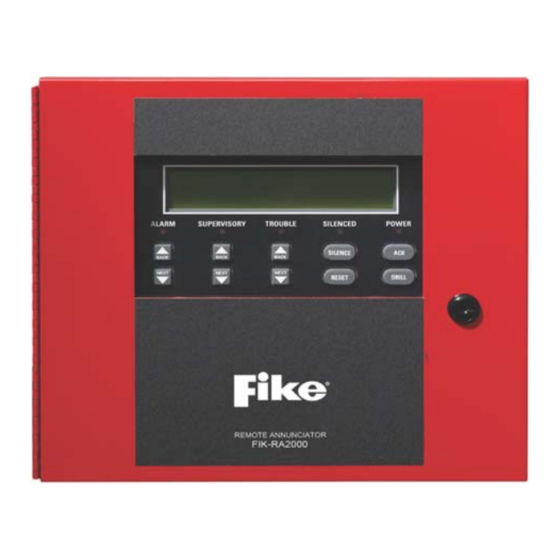
The FIK-RA2000 is an optional 4x40 remote annunciator that can be
surface or flush-mounted.
BACK
NEXT
Figure 1 FIK-RA2000 Remote Annunciator
1.1 Compatibility
The FIK-RA2000 is compatible with the Fike Series FACPs. For more
information, refer to the FACP Manual.
1.2 Specifications
Operating Voltage:
Current
Standby Current: 27mA
Alarm Current:
Operating Temperature:
Dimensions Flush Mount:
Surface Mount:
Table 1 Specifications
2 Installation
1.
Ensure power is turned off at the panel.
2.
Mount the FIK-RA2000 in the desired location. See Section 2.1.
3.
Connect the FIK-RA2000 to the panel. See Figure 5.
4.
Use the DIP switches on the back of the FIK-RA2000 to assign an
ID number. Refer to the FACP manual.
5.
The FIK-RA2000 module must be added to the system through
FACP programming. JumpStart can be used to automatically add
the module or it may be added manually. Refer to the FACP Manual
for more information.
BACK
BACK
NEXT
NEXT
24VDC
53mA
32° to 120° F (0° to 49° C)
Overall:
12.25" W x 11.5" H x 0.875" D
(31.1 cm W x 29.2 cm H x 2.2 cm D)
Backbox: 9.25" W x 8.375"H
(23.5cm W x 21.27cm H)
Including trim ring:
12.25" W x 11.5" H x 3.0" D
(31.1 cm W x 29.2 cm H x 7.6 cm D)
FIK-RA2000 Annunciator
Product Installation Document
PN LS10261-001FK-E:B 5/25/2022 ECN: 00003636
2.1 Mounting
2.1.1 Flush Mounting
Follow these steps to flush mount the FIK-RA2000.
1.
The backbox dimensions are 9.25" W x 8.375" H. The minimum
depth required is 2". Mount the backbox using the mounting holes
shown below.
Figure 2 FIK-RA2000 Backbox Mounting
2.
Remove knockouts as needed for wires. There are 10 knockouts
available, two on each side and two in the back of the cabinet.
3.
Wire the annunciator board to the main control panel as shown in
Figure 5.
4.
Attach the annunciator and door assembly to back box as shown
below using the supplied screws.
Figure 3 Attaching Annunciator/Door Assembly
mounting holes
mounting holes
Advertisement

Subscribe to Our Youtube Channel
Related Manuals for Fike FIK-RA2000


Summary of Contents for Fike FIK-RA2000
- Page 1 Mount the FIK-RA2000 in the desired location. See Section 2.1. Connect the FIK-RA2000 to the panel. See Figure 5. Use the DIP switches on the back of the FIK-RA2000 to assign an ID number. Refer to the FACP manual. The FIK-RA2000 module must be added to the system through FACP programming.
- Page 2 3 Wiring Connections 2.1.2 Surface Mounting The RA-100TR Red Trim Ring kit is available for use when surface Wire the FIK-RA2000 to the FACP as shown in below. mounting the FIK-RA2000. Remove the desired knockout. remote annunciator Mark and pre-drill hole in the wall for the center top keyhole (back view) mounting bolt.
Need help?
Do you have a question about the FIK-RA2000 and is the answer not in the manual?
Questions and answers