
Related Manuals for airmet AirMetER-AX


Summary of Contents for airmet AirMetER-AX
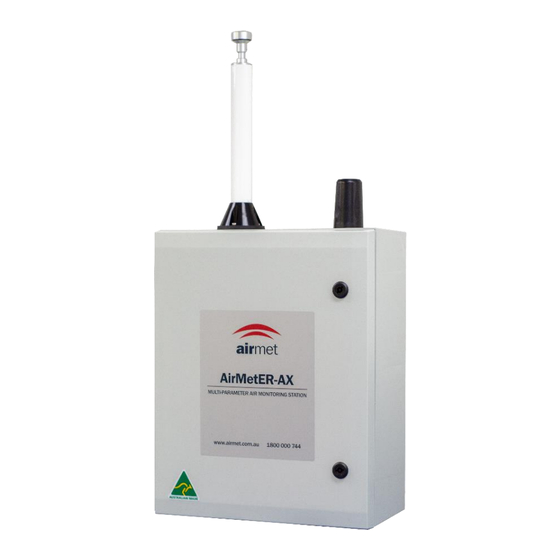
- Page 1 AIR-MET SCIENTIFIC AirMetER-AX MULTI-PARAMETER ENVIRONMENTAL MONITORING STATION Service Guide Before operating the unit, please read this service guide thoroughly and retain for future reference Revision 1 | November 2023...
-
Page 2: Table Of Contents
6. Frequency Tables ..............................13 Calibration Frequency ............................13 Filter Replacement ..............................13 Module Replacement ............................13 7. Instrument Layout..............................14 AirMetER-AX II Layout ............................14 AirMetER AX-IV Layout ............................15 8. Troubleshooting Guide ............................16 9. Spare Parts ................................18 Contact Information..............................19... -
Page 3: Copyright Notice
COPYRIGHT NOTICE These help materials or any part thereof may not, without the written consent of Air-Met Scientific, be copied, reprinted, or reproduced in any material form including but not limited to photocopying, transcribing, transmitting, or storing it in any medium or translating it into any language, in any form or by any means, be it digitally, electronic, mechanical, xerographic, optical, magnetic, or otherwise. -
Page 4: Warranty & Service
Air-Met Scientific maintains instrument service facilities nationwide. Should your instrument require service, you may contact us on 1800 000 744 or at service@airmet.com.au. Alternatively, instrument service may be booked by completing our online service request form at the following URL: https://www.airmet.com.au/services/book-a-service... -
Page 5: Filter Exchange
1. FILTER EXCHANGE The AirMetER-AX can contain up to four filters: 9933-05-CQ - Dust filter 1756-K-EACH - Gas filter KAM-SF9 - NOx filter 121-5866 - Pneumatic silencer It is recommended that these filters be exchanged no less than annually. The filters should be monitored and inspected at regular intervals in new applications to gain an insight into how long the filters last before discolouration. -
Page 6: Tsp Head & Heated Inlet Cleaning
2. TSP HEAD & HEATED INLET CLEANING A TSP head should be installed on all heated inlets at factory and while installed in the field, these need to be periodically cleaned. The time interval between cleaning varies depending on the application and location of the device. -
Page 7: Flow Rate Calibration
3. FLOW RATE CALIBRATION DX II FLOW RATE CALIBRATION Attach a 0.4-5L/m rotameter (320-4A5) to the inlet of the AirMetER-AX, the flowmeter should indicate 2L/m ± 5%. Should this be out of tolerance, ensure there are no leaks and that there is pressure when blocking the heated inlet. Manual adjustment of the pump flow rate may be completed to achieve the flow rate as depicted below. -
Page 8: Installation
40-105mm in diameter. An adjustable spanner or flat- blade screwdriver may be utilised to either tighten or release the pipe clamp to suit the intended structure diameter. Care should be taken during installation to ensure the AirMetER-AX is level and firmly secured. Figure 4.1 – Mounting Brackets... -
Page 9: Location & Mounting Of Monitor
LOCATION & MOUNTING OF MONITOR Air-Met Scientific recommends the monitor is pole or tripod mounted in an open area, free from buildings and other obstructions that may have an influence on measurements. Figure 4.3 – External and Mounting-Point Dimensions (mm) -
Page 10: Module & Part Removal/Replacement
Do not use a power drill on the particulate sensor module screws as this may cause damage to the instrument. Ensure that the AirMetER-AX is switched off and disconnected from any power source while removing and replacing the particulate sensor module. -
Page 11: Dxiv Particulate Sensor Module Removal & Replacement
Do not use a power drill on the particulate sensor module screws as this may cause damage to the instrument. Ensure that the AirMetER-AX is switched off and disconnected from any power source while removing and replacing the particulate sensor module. -
Page 12: Heated Inlet Removal & Replacement
Figure 5.11 – Heated Inlet 1. Inside the AirMetER-AX unplug the heated inlet cable from the plug secured to the side of the enclosure. 2. Using a 2mm allen key loosen the grub screw to ensure the heated inlet can slide out of the tube adapter (the tube adapter is shown on the next slide). -
Page 13: Frequency Tables
6. FREQUENCY TABLES CALIBRATION FREQUENCY SENSOR TYPE CALIBRATION FREQUENCY Laser Particulate Sensor Yearly Sound/Noise Monitor Yearly Gas Sensor 6 months FILTER REPLACEMENT FILTER DESCRIPTION PART NUMBER REPLACEMENT FREQUENCY Dust Filter 9933-05-CQ Yearly* Gas Filter 17576-K-EACH Yearly* Pneumatic Silencer 121-5866 Yearly* NOx Filter for Air-MetER AX-3 KAM-SF9 Yearly*... -
Page 14: Instrument Layout
7. INSTRUMENT LAYOUT AIRMETER-AX II LAYOUT Parts may vary according to configuration 14 14... -
Page 15: Airmeter Ax-Iv Layout
AIRMETER AX-IV LAYOUT Parts may vary according to configuration 15 15... -
Page 16: Troubleshooting Guide
8. TROUBLESHOOTING GUIDE ISSUE SOLUTIONS 1. Are the pump modules plugged in at the top as No air flow at the exhaust displayed in Figure 3.2? 2. Are the filters blocked and need replacement? 3. Trace the tubing from the outlet of the top particulate pump module down to the external exhaust. - Page 17 1. Are the pump modules plugged in at the top as Readings are low displayed in Figure 3.2? 2. Check to make sure there is flow at the external exhaust. 3. Check that the flow rates at the gas and heated inlets are as detailed from II.
-
Page 18: Spare Parts
9. SPARE PARTS PART NUMBER DESCRIPTION TF-TRI-AL Tripod Mounting AMS/200S/170B/15M/9C Remote Power System 10085 TSP Head 10090 Heated Inlet LPF-60-12-AUP Power Supply (240V) Air-MetER AX-IV Particulate Sensor Module (PM , PM , PM , PM and TSP) 4.25 Air-MetER AX-11 Particulate Sensor Module (PM and PM Air-MetER AX-1... -
Page 19: Contact Information
P.O. Box 133 Nunawading VIC 3131 Australia Phone: 1800 000 744 +61 3 8878 3300 Fax: 1800 000 774 +61 3 8878 3344 Web: www.airmet.com.au Email: sales@airmet.com.au Air-Met Scientific Pty Ltd, Australia © 2023 Air-Met Scientific All rights reserved. 19 19...
Need help?
Do you have a question about the AirMetER-AX and is the answer not in the manual?
Questions and answers