
Related Manuals for RS PRO 3101


Summary of Contents for RS PRO 3101
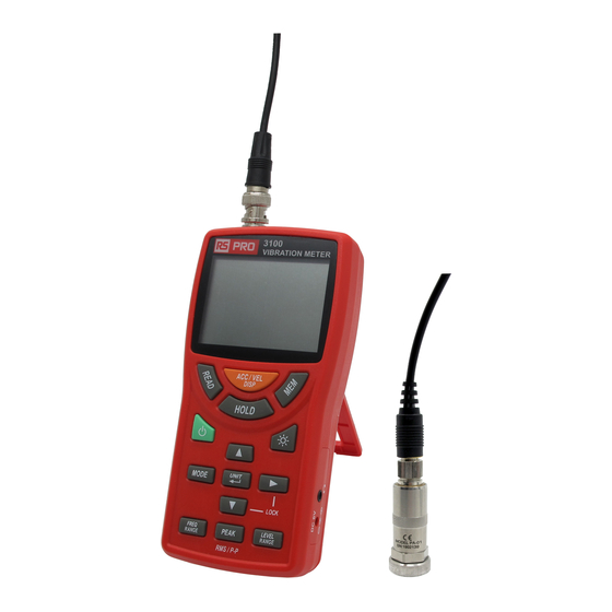
- Page 1 User Manual RS PRO 3101 stock number: 254-3501 VIBRATION METER Datalogger UNIT rspro.com...
-
Page 2: Table Of Contents
CONTENTS Title Page 1. SAFETY INFORMATION ............. 1 2. INTRODUCTION FEATURES..........2 3. SPECIFICATIONS..............3 4. PARTS & CONTROLS............8 4-1 Description of Parts & Control Keys........ 8 4-2 Description of Display ........... 14 5. PREPARATIONS ............... 17 5-1 Power Supply..............17 5-2 Cable and Accelerometer Connection ...... -
Page 3: Safety Information
1. SAFETY INFORMATION To prevent bodily injury or damage to the meter, the following cautions must be observed. CAUTION Do not place the meter on an unstable place (shaky table or sloping place). If the meter falls down, it is very dangerous. Do not use and storage the place which moisture or dust, and where air with high salt or sulphur content, or other gase or chemicals. -
Page 4: Introduction Features
2. INTRODUCTION FEATURES The meter is designed mainly for routine maintenance and monitoring of rotational and other industrial machinery. Acceleration, velocity, and displacement can be easily measured using a suitable frequency range, allowing comprehensive and precise evaluation of machine vibrations. Applications: Industrial hygiene investigations Industrial machinery check-ups... -
Page 5: Specifications
3. SPECIFICATIONS Accelerometer Model PA-01 specification 1. Sensor: Voltage output type (built-in preamplifier) 2. Type: CCLD (Constant Current Line Drive) 3. Sensitivity: Listed on supplied calibration chart of PA-01 4. Transverse sensitivity: 5% or less 5. Frequency characteristics: 5Hz to 10kHz (±10%), 10kHz to 15kHz (±3dB) 6. - Page 6 Upper measurement limit for velocity and displacement measurements is restricted by maximum input acceleration. Frequency range Acceleration (ACC): 3Hz ~ 1kHz, 3Hz ~ 5kHz, 1Hz ~ 100Hz, 3Hz ~ 20kHz Velocity (VEL): 10Hz ~ 1kHz, 3Hz ~ 1kHz Displacement (DISP): 10Hz ~ 500Hz, 3Hz ~ 500Hz The above figures refer to the point where response is down by 10% from flat response, due to the action of a high-pass filter or low-pass filter.
- Page 7 For accelerometers sensitivity is 10 ~ 99 mV/(m/s²) Acceleration (ACC): 0.1, 1, 10, 100 m/s² Velocity (VEL): 1, 10, 100 mm/s Displacement (DISP): 0.01, 0.1, 1, 10 mm Indication characteristics Acceleration (ACC): EQ PEAK, RMS Velocity (VEL): RMS, EQ PEAK Displacement (DISP): EQ PEAK, EQ p-p, RMS EQ PEAK = RMS x , EQ p-p = EQ PEAK x 2...
- Page 8 Headphone output: Vibration sound monitor Operating temperature and humidity: -10 ℃ ~ +50 ℃ , max. 90%RH Storage temperature and humidity: -20 ℃ ~ +60 ℃ , max. 90%RH Power requirements: Four IEC R6 size AA batteries (zinc-carbon batteries, alkaline batteries, or nickel-metal hydride batteries) or AC adapter (VA-03 for 100 to 240V AC, optional)
- Page 9 Supplied accessories: Piezoelectric accelerometer PA-01x1 Accessories for PA-01 Curled cable VA-02 x 1 Magnet attachment VA-01 x 1 IEC R6 batteries zinc-carbon x 4 Instruction manual x 1 PA-01 calibration chart x 1 CD software x 1 Micro-USB cable x 1 Optional accessories: AC adapter VA-03 M5x0.8 screw VA-04 Hex flat attachment VA-05...
-
Page 10: Parts & Controls
4. PARTS & CONTROLS 4-1 Description of Parts & Control Keys VIBRATION METER REC MAX Datalogger UNIT 1. BNC input connector: The piezoelectric accelerometer is to be connected here, using the supplied curled cable. The power supply to drive the accelerometer (24V, 2mA) is always output from the BNC input connector. - Page 11 3. ACC/VEL DISP key: Press this key to select measurement of acceleration (ACC m/s²), velocity (VEL mm/s) or displacement (DISP mm) mode. 4. READ key: Press this key to enter or exit the manual data memory READ mode. 5. MEM key: Press this key one time to store the one data to memory.
- Page 12 11. UNIT/↵ key: UNIT: In the measurement mode, press “UNIT” key to change the measurement units. ↵ : In the setting mode, press ↵ key to enter or exit a setting mode or store the displayed setting. 12. ► key: In the setting mode, press ►...
- Page 13 15. PEAK RMS/P-P key: Press this key to select the display mode for each measurement mode. Once the setting is made, it will be used every time the measurement mode is selected. The following settings are available. Acceleration (ACC): EQ PEAK, RMS Velocity (VEL): RMS, EQ PEAK Displacement (DISP): EQ PEAK, EQ P-P, RMS The display characteristics settings have the following meaning.
- Page 14 When using an accelerometer with a sensitivity of 0.1 to 0.99 mV/(m/s²). ACC: 10, 100, 1000, 10000 m/s² VEL: 100, 1000, 10000 mm/s DISP: 1, 10, 100, 1000 mm When using an accelerometer with a sensitivity of 10 to 99 mV/(m/s²). ACC: 0.1, 1, 10, 100 m/s²...
- Page 15 19. Battery compartment: Four batteries (IEC R6, size AA) are inserted here. 20. USB socket: micro USB interface Piezoelectric accelerometer Curled cable (VA-02) BNC connector Piezoelectric accelerometer PA-01 BNC connector: Insert this connector into the input connector on the meter. Piezoelectric accelerometer PA-01: Detects vibrations and converts then into an electric signal.
-
Page 16: Description Of Display
4-2 Description of Display REC MAX 1. Date/time: Shows the current, memory or recorded year, month/day, hour/minute, or second. : Year÷Month : Day-Hour : Minute : Second 2. HOLD : Data hold indicator 3. Full-scale value: Shows the full-scale value of the current range. - Page 17 : Battery status indicator Four segment indicator shows the remaining batteries capacity. When the indication starts to flash, correct measurement is no longer possible. Replace the batteries immediately. 7. Data memory: M : Manual stored measured value to memory indication, M disappear one time store one data into the memory.
- Page 18 11. Display mode: RMS: True effective value EQ PEAK: Equivalent peak value (RMSx EQ P-P: Equivalent peak-to-peak value (EQ PEAK x 2) (only Displacement) 12. Measurement value: Numeric indication of measurement value in intervals of approx. 1 second. 13. Measurement mode unit indicator: m/s²...
-
Page 19: Preparations
5. PREPARATIONS The required matter is indicated before beginning measurement. Always set the power to OFF before inserting batteries and making any connections. 5-1 Power Supply The meter can be powered by four IEC R6 (size AA) batteries or by the optional AC adapter VA-03 (for 100 to 240V AC). Battery installation: When the meter is in operation, press key to turn off the... - Page 20 Selecting the battery type: Set the battery type used for the meter. The remaining battery capacity corresponding to the selected battery type is displayed. Available settings are Zinc-carbon, Alkaline and Ni-MH (nickel-metal hydride) battery. 1. Press key to turn on the meter. 2.
-
Page 21: Cable And Accelerometer Connection
5-2 Cable and Accelerometer Connection Important Make sure that the power of the meter is turn to off before connecting or disconnecting the cable and accelerometer. Make the connection with the supplied curled cable VA-02, as shown in the illustration as follows. Curled cable (VA-02) BNC connector... -
Page 22: Accelerometer Mounting
5-3 Accelerometer Mounting There four basic methods attaching accelerometer measurement object. accelerometer mounting method greatly affects the contact resonance frequency. Please perform suitable method in consideration of the advantages and disadvantages of the four methods are outlined below. Contact resonance frequency: When the contact area between the accelerometer and the measurement object is partially deformed, a kind of spring system is created which vibrates at a frequency that is... - Page 23 Screw mounting (VA-04): Piezoelectric accelerometer (PA-01) Screw hole M5, P=0.8 M5 screw Effective depth 4 (VA-04) option 0.4a~1.6a Measurement object rspro.com...
- Page 24 This mounting method is the best vibration characteristics. The mounting surface must have a surface smoothness of 0.4a ~ 1.6a. Use a fastening torque of 1 ~ 1.5 N-m for the accelerometer and the M5 screw that joins the accelerometer to measurement object.
- Page 25 Flat magnet mounting (VA-01): Although a magnet can be used when the measurement subject is made of the metal which sticks to a magnet, due to this mounting method the contact resonance frequency will be quite low, this method is mainly suited for vibration measurements in the medium to low frequency range.
- Page 26 (PA-01) Piezoelectric accelerometer Magnet attachment (VA-01) Measurement object (ferromagnetic) Rod attachment mounting (VA-06): Pressing the accelerometer against the measurement object with a rod is the simplest method, but it is only suitable for Piezoelectric accelerometer measurement below 500Hz, due to the contact resonance frequency will be very M5 screw low.
-
Page 27: Setup
6. SETUP 6-1 Setting the Real-Time 1. Press key to turn on the meter. 2. Press “MODE” key for 3 seconds to enter the setting mode, the “ ” mark is displayed. 3. Press ▼ key one time to select this mode, the “ ”... -
Page 28: Setting The Accelerometer Sensitivity
” mark is displayed. 4. Press ↵ key to enter this mode, the “ ” mark is flashing displayed. 5. Press ▲ key to select “ ” or “ ”. 6. If select “ ” then press ↵ key to disable auto power off function and exit. - Page 29 7. Press ↵ key to store the setting and exit this mode. 8. Press “MODE” key again to exit setting mode. Piezoelectric Accelerometer Calibration Data PA- 01 Model 1612278 Serial No. 4.82 Voltage Sensitivity mV/(m/s (159.2 Hz) Inspectedby ℃ Temperature 2016.12 Date RS PRO rspro.com...
-
Page 30: Vibration Measurement
7. VIBRATION MEASUREMENT 7-1 Vibration Measurement 1. Press key to turn on the meter. 2. Press “ACC/VEL/DISP” key to select the measurement mode. Press “FREQ RANGE” key to select the frequency range which suits the measurement purpose. Press “LEVEL RANGE” key to select the measurement range. -
Page 31: Manual Data Memory And Read
3. Press “PEAK/RMS/P-P” key to select the display mode as follows. ACC: EQ PEAK or RMS VEL: RMS or EQ PEAK DISP: EQ PEAK, RMS, or EQ P-P 4. When the input signal overloads the circuitry of the meter, the indication “ OVER ” appears. Using the “LEVEL RANGE”... -
Page 32: Maximum & Minimum Recording Measurement
3. To clear the manual memorized data Press key to turn on the meter. Press “MODE” key for 3 seconds to enter the setting mode, the “ ” mark is displayed. Press ▼ key 6 times to select this mode, the “ ”... -
Page 33: Calibration
7-4 Calibration Using Handheld Shake Calibrator (159.2Hz, 10m/s² rms or 1g rms) to verify the Accelerometer sensitivity. 1. Press key to turn on the meter. 2. Fix the accelerometer to the calibrator, then turn on the calibrator. 3. Press “MODE” key for 3 seconds to enter the setting mode, the “... -
Page 34: Auto Datalogging
7-5 Auto Datalogging Only micro SD CARD 4GB ~ 32GB can be used. Maximum 99 blocks can be used. 1. Clear the auto memorized data Press key to turn on the meter. Press “MODE” key for 3 seconds to enter the setting mode, the “... -
Page 35: Auto-Cycle Timer Datalogging
5 Press ▲ or ▼ key to select desired interval time “ ” is 1s, 2s, 5s, 10s, 20s, 30s, 1m, 2m, 5m, 10m, 20m, 30m or 60m. 6 Press ↵ key to store the selecting and exit. 7 Press “MODE” key again to exit setting mode. 3. -
Page 36: Cycle Timer Datalogging
6. Using key, position the cursor on the time element to adjust. 7. Using ▲ and ▼ keys to setting the selected time element value. 8. Press ↵ key to enter the Record-Time setting mode, the “ ” mark and the flicking number of hour are displayed. 9. - Page 37 4. Press ▼ key 4 times to select this mode, the “ ” mark is displayed. 5. Press ↵ key to enter the Start-Time setting mode, the “ ” mark and the flicking number of year are displayed. 6. Using key, position the cursor on the date or time element to adjust.
-
Page 38: Rtc Button Cell Battery Replacement
8. RTC BUTTON CELL BATTERY REPLACEMENT Open meter bottom cover, find the button cell battery. You can change button cell battery. CR1220 Button cell battery 9. MAINTENANCE Cleaning: Periodically wipe the case with a damp cloth and mild detergent. Do not use abrasives or solvents. Clean and dry as required. - Page 39 Limited Warranty This meter is warranted to the original purchaser against defects in material and workmanship for 3 years from the date of purchase. During this warranty period, RS Components will, at its option, replace or repair the defective unit, subject to verification of the defect or malfunction. This warranty does not cover fuses, disposable batteries, or damage from abuse, neglect, accident, unauthorized repair, alteration, contamination, or abnormal conditions of operation or handling.
- Page 40 Africa Japan RS Components SA RS Components Ltd. P.O. Box 12182, West Tower (12th Floor), Vorna Valley, 1686 Yokohama Business Park, 20 Indianapolis Street, 134 Godocho, Hodogaya, Kyalami Business Park, Yokohama, Kanagawa 240-0005 Kyalami, Midrand Japan South Africa www.rs-components.com www.rs-components.com Asia U.S.A RS Components Pte Ltd.
Need help?
Do you have a question about the 3101 and is the answer not in the manual?
Questions and answers