Table of Contents
Advertisement
Available languages
Available languages
Quick Links
Advertisement
Chapters
Table of Contents

Subscribe to Our Youtube Channel
Related Manuals for GF PSO 701


Summary of Contents for GF PSO 701
- Page 1 GF Piping Systems Instruction manual PSO 701 Butt Fusion Machine...
- Page 2 All rights reserved, in particular the rights of duplication and distribution as w ell as translation. Duplication and reproduction in any form (print, photocopy, m icrofilm or electronic) require the w ritten permission of Georg Fischer Om icron S.r.l..
-
Page 3: Table Of Contents
Operating instructions PSO 701 Table of contents Table of contents Page About this manual Warning notice Other symbols and notices Abbreviations Safety instructions Proper use General safety measures Working with safety in mind Disposal General Introduction Range of application Copyright... -
Page 4: About This Manual
Operating instructions PSO 701 1 About this manual About this manual The warning notices, symbols and their meanings as used in this manual are explained below to help you quickly understand the format of this instruction manual and how to use the machine safely. -
Page 5: Other Symbols And Notices
1 About this manual Operating instructions PSO 701 Other symbols and notices Symbol Meaning This notice contains especially important information. Important Attention Mandatory: you must observe this regulation. Call for action in a particular sequence. You must do something here. -
Page 6: Safety Instructions
2 Safety instructions Safety instructions The PSO 701 Butt Fusion Machine (hereinafter referred to as PSO 701) is designed according to the latest standards of technology. Using it for purposes other than those described in this manual may cause injury to the operator or to others. -
Page 7: Disposal
2 Safety instructions Operating instructions PSO 701 Danger of cutting hands! The planer blades are sharp! Danger of cutting hands on the planer disk. Warning Do not touch the rotating planer disk. Danger of burning! The heater is hot (220 °C)! Danger of burning hands on the hot heater. -
Page 8: General
General Introduction This instruction manual was written for those persons responsible for the operation and care of the PSO 701. It is expected and assumed that such persons have read, understood and will abide by the manual in its entirety. -
Page 9: Product Design, Equipment
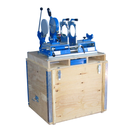
4 Product design, equipment Operating instructions PSO 701 Product design, equipment Design 1 Pressure lever 2 Heater 3 Planer 4 Wooden case 5 Slide stop 6 Pipe support 7 Basic machine 8 Clamping plates left/right... -
Page 10: Standard Equipment
Operating instructions PSO 701 4 Product design, equipment Standard equipment • Basic machine Compact and sturdy design – Hardened, chrome plated guide shaft – W ooden case – for transportation and protection of machine as – well as for erconomically correct working position Exact pressure adjustment via direct manual load transfer –... -
Page 11: Technical Specifications
5 Technical specifications Operating instructions PSO 701 Technical specifications Drive/Power: Electromotor 420 W Electric planer Voltage: 230 V/115 V Power: 800 W Heating element Voltage: 230 V/115 V Machine complete Power: 1220 W Voltage: 230 V/115 V Characteristic data Machine description:... -
Page 12: Transport And Assembly
Normally, the machine and all the accessories are delivered in a cardboard box on a pallet. Sensitivity Special care must be taken when transporting the PSO 701 in order to prevent damage from impact or improper loading and unloading. All movable parts must be fixed in place. -
Page 13: Assembly
6 Transport and assembly Operating instructions PSO 701 Assembly 1. Unpack basic machine (7) and wooden case (4). 2. Set basic machine (7) on the wooden case (4) and fix the clamps with the 2 star knop screws (9). 3. Assemble the pressure lever (1). -
Page 14: Fusion Preparation
(humidity, ambient temperature <+ 5 °C, extreme direct exposure to sun) with such measures as pre-warming the fusion materials, tents, heating. For optimal use of the PSO 701, operating personnel should be specially trained by Georg Fischer Omicron s.r.l.. In-depth knowledge of the machine and it´s components and competence rule out handling errors... -
Page 15: Fusion
8 Fusion Operating instructions PSO 701 Fusion The basics of butt fusion For butt fusion with a heating element, the parts to be joined (pipe/pipe, pipe/fitting or fitting/fitting) are heated to fusion temperature in the fusion area and are fused under pressure without the use of additional materials. -
Page 16: The Fusion Process
Operating instructions PSO 701 8 Fusion The fusion process 8.2.1 Preparing the fusion surfaces 1. Clamp pipe/pipe, pipe/fitting or fitting/fitting in the clamping ca. 1 ca. 1 elements. The pipe-/fitting ends to be joined should be clamped 1 cm prominent of the clamping element. Check the axial alignment. - Page 17 8 Fusion Operating instructions PSO 701 Black button and ON-/OFF- switch simultaneosly pressed: Planer – motor runs continuosly 4. Switch ON planer motor. Caution Hold the planer with the right hand. Planer pressure which is too high over a long period of time will damage the planer drive or motor.
-
Page 18: Fusion Process
Operating instructions PSO 701 8 Fusion 8.2.2 Fusion process The PTFE coating of the heating element must be protected from mechanical damage and/or dirt. Heating element (2) with demaged PTFE -covering has to be replaced. Non-observance affects the quality of the joining, see Chapter 9.1, from pg 26. - Page 19 8 Fusion Operating instructions PSO 701 Heat soak (of the fusion material) For PE: 10 x wall thickness in mm For PP: Interpolate the intermediate values. Change-over (removing the heating element (2)) The change-over time should be as short as possible.
-
Page 20: Visual Check Of Welding Bead
Operating instructions PSO 701 8 Fusion Visual check of welding bead Immediately after removing the welded pipes/fittings visually check the part for correct cultivated double bead and the k-value. k > 0 Ev en double bead Example Pipe/fitting Heater temperature 220 °C... -
Page 21: Fusion Data
8 Fusion Operating instructions PSO 701 Fusion data Heating element butt fusion of PE Fusion table/DVS 2207/1 guidelines Heating element temperature 220 °C ± 10 °C Nominal wall Equalize Heat soak Change-over Join Cooling thickness Bead height on Heat soak time = 10 x... - Page 22 Operating instructions PSO 701 8 Fusion Process steps for heating element butt fusion He ating element b utt fusion of PE Time/Pressure tables...
- Page 23 8 Fusion Operating instructions PSO 701 He ating element b utt fusion of PE Time/Pressure tables...
- Page 24 Operating instructions PSO 701 8 Fusion He ating element b utt fusion of PE Time/Pressure tables...
- Page 25 8 Fusion Operating instructions PSO 701 He ating element b utt fusion of PE Time/Pressure tables...
- Page 26 Operating instructions PSO 701 8 Fusion He ating element b utt fusion of PP Fusion table guidelines Heating element temperature 210 °C ± 10 °C Nominal wall Equalize Heat soak Change-over Join Cooling Bead height on the (heat soak Time until max...
- Page 27 8 Fusion Operating instructions PSO 701 He ating element b utt fusion of PP Time/Pressure tables...
- Page 28 Operating instructions PSO 701 8 Fusion He ating element b utt fusion of PP Time/Pressure tables...
-
Page 29: Maintenance
Maintenance The PSO 701 should be checked and cleaned periodically. Normal care of the PSO 701 is limited to periodic cleaning of the outside. The guiding elements have to be free of dirt. The clamping units have to Basic machine be free of dirt. -
Page 30: 10 Customer Service
Operating instructions PSO 701 10 Customer Service 10 Customer Service There is a separate spare part list for ordering replacement parts. If repairs are necessary, please contact your local representative. Please indicate the following information: Machine type ASM 160 •... - Page 31 Operating instructions PSO 701 11 Customer Service...
- Page 32 Operating instructions PSO 701 11 Customer Service...
- Page 33 Operating instructions PSO 701 11 Customer Service...
- Page 34 Declaration of conformity Konformitätserklärung Dichiarazione di conformità Déclaration de conformité Declaracion de conformidad The following product : Welding Machine Die Bauart der Machine : Schweissmachine Il seguente prodotto : Saldatrice Le produit suivant: Machine à souder El producto siguiente : Maquina de fusión was designed, constructed and manufactured in accordance with the following EC guidelines: ...
- Page 36 GF Piping Systems Worldwide at home Our sales companies and representatives ensure local customer support in over 100 countries www.gfps.com Argentina / Southern South America Finland Mexico / Northern Latin America Singapore Georg Fischer Central Plastics Georg Fischer AB Georg Fischer S.A. de C.V.
- Page 37 GF Piping Systems Betriebsanleitung PSO 701 Stumpfschweissmaschine...
- Page 38 Alle Rechte, insbesondere das Recht der Vervielfältigung und Verbreitung sowie der Übersetzung, vorbehalten.Vervielfältigungen oder Reproduktionen in jeglicher Form (Druck, Fotokopie, Mikrofilm oder Datenerfassung) bedürfen derschriftlichen Genehmigung durch die Georg Fischer Om icron S.r.l..
- Page 39 Betriebsanleitung PSO 701 Inhaltsverzeichnis Inhaltsverzeichnis Seite Zu dieser Anleitung Warnhinweise Weitere Symbole und Auszeichnungen Abkürzungen Sicherheitshinweise Bestimmungsgemässe Verwendung Sicherheitsvorschriften Sicherheitsbewusst arbeiten Entsorgung Allgemeines Einleitung Anwendungsbereich Urheberrecht Aufbau des Produkts, Ausrüstung Aufbau Standard-Ausrüstung Technische Daten Kenndaten Transport und Montage Verpackung Empfindlichkeit Zwischenlagerung Prüfen des Lieferumfangs...
-
Page 40: Zu Dieser Anleitung
Betriebsanleitung PSO 701 1 Zu dieser Anleitung Zu dieser Anleitung Für das schnelle Erfassen dieser Anleitung und das sichere Umgehen mit der Maschine werden Ihnen hier die in der Anleitung verwendeten W arnhinweise, Hinweise und Symbole sowie deren Bedeutung vorgestellt. -
Page 41: Weitere Symbole Und Auszeichnungen
1 Zu dieser Anleitung Betriebsanleitung PSO 701 Weitere Symbole und Auszeichnungen Symbol Bedeutung Hinweise: Enthalten besonders wichtige Informationen Wichtig zum Verständnis. Hinweis Gebot: Dieses Symbol müssen Sie beachten. Handlungsaufforderung in einer Handlungsabfolge: Hier müssen Sie etwas tun. Allein stehende Handlungsaufforderung: Hier müssen Sie ... -
Page 42: Sicherheitshinweise
Jede Person, die im Betrieb des Anwenders mit der Montage, De- und Remontage, Inbetriebnahme, Bedienung Instandhaltung (Inspektion, W artung, Instandsetzung) der PSO 701 befasst ist, muss die komplette Bedienungsanleitung besonders Abschnitt 1 "Sicherheitshinweise" gelesen und verstanden haben. Dem Anwender wird empfohlen, sich dies jeweils schriftlich bestätigen zu lassen. -
Page 43: Sicherheitsbewusst Arbeiten
Alle Arbeiten sicherheitsbewusst durchführen. • Zu Ihrer persönlichen Sicherheit sowie als Voraussetzung für einen sicheren und bezüglich Handhabung optimalen Betrieb ist eine praxisgerechte Installation der PSO 701 unumgänglich. Schnittverletzungen an den Händen! Scharfe Hobelmesser! Schnittverletzungen an den Händen bei Berühren der Hobelscheiben. -
Page 44: Allgemeines
Allgemeines Einleitung Diese Betriebsanleitung ist für diejenigen Personen geschrieben, die für Anwendung und Pflege der PSO 701 verantwortlich sind. Es wird erwartet und vorausgesetzt, dass dieser Personenkreis die Betriebsanleitung liest, versteht und in allen Punkten beachtet. Nur mit Kenntnis dieser Betriebsanleitung können Fehler an der PSO 701 vermieden und ein störungsfreier Betrieb gewährleistet werden. -
Page 45: Urheberrecht
3 Allgemeines Betriebsanleitung PSO 701 Urheberrecht Urheberrecht für diese Betriebsanleitung liegt Georg Fischer Omicron S.r.l.. Diese Betriebsanleitung ist für das Montage-, Bedienungs- und Überwachungspersonal bestimmt. enthält Vorschriften Zeichnungen technischer Art, die weder vollständig noch teilweise vervielfältigt, verbreitet oder zu Zwecken des W ettbewerbs unbefugt verwendet oder anderen mitgeteilt werden dürfen. -
Page 46: Aufbau Des Produkts, Ausrüstung
Betriebsanleitung PSO 701 4 Aufbau des Produkts, Ausrüstung Aufbau des Produkts, Ausrüstung Aufbau 1 Fügedruckhebel 2 Heizelement 3 Hobeleinheit 4 Holzkiste 5 Feststellschraube 6 Rohrauflage 7 Grundmaschine 8 Spannstellen links/rechts... -
Page 47: Standard-Ausrüstung
4 Aufbau des Produkts, Ausrüstung Betriebsanleitung PSO 701 Standard-Ausrüstung • Grundmaschine Kompakte, stabile Bauweise – Gehärtete, hartverchromte Führungswellen – Stahlrohr-Untergestell für ergonomisch richtiges Arbeiten – Exakte Druckeinstellung durch direkte manuelle Kraftübertragung – • Hobeleinheit Optimierte Schneidengeometrie für gleichmässiges und ratterfreies –... -
Page 48: Technische Daten
Betriebsanleitung PSO 701 5 Technische Daten Technische Daten Antrieb/Leistung: Elektromotor 560 W , 230 V Hobeleinheit Spannung: Elektromotor 600 W , 115 V Leistung: 800 W Heizelement Spannung: 230 V/115 V Leistung: 1360 W , 230V Maschine Spannung: 1400 W , 115V... -
Page 49: Transport Und Montage
Stösse vermeiden. Die PSO 701 selbst ist mit der üblichen Sorgfalt zu behandeln. Zwischenlagerung W ird die PSO 701 nicht unmittelbar nach Anlieferung eingesetzt, muss die Maschine an einem geschützten Ort gelagert und ordnungsgemäss abgedeckt werden. Prüfen des Lieferumfangs Die Vollständigkeit (Anzahl Kisten, Paletten, Pakete) und deren... -
Page 50: Montage
Betriebsanleitung PSO 701 6 Transport und Montage Montage 1. Grundmaschine (7) und Stahlrohr-Untergestell (4) auspacken. 2. Fügedruckhebel (1) einschrauben. -
Page 51: Schweissvorbereitung
7 Schweissvorbereitung Betriebsanleitung PSO 701 Schweissvorbereitung Allgemeine Hinweise Schweissbereich ungünstigen W itterungseinflüssen (Feuchtigkeit, Umgebungstemperatur <+ 5 °C, extreme direkte Sonneneinstrahlung) durch Massnahmen Vorwärmen Schweissgutes, Einzelten, Beheizen zu schützen. Ausschlaggebend für ein optimales Arbeiten Einsatz Bedienungspersonal das bei Georg Fischer geschult wurde. Fundierte... -
Page 52: Schweissvorgang
Betriebsanleitung PSO 701 8 Schweissvorgang Schweissvorgang Grundlagen zum Stumpfschweissen Beim Heizelement-Stumpfschweissen werden die zu verbindenden Teile (Rohr/Rohr, Rohr/Fitting oder Fitting/Fitting) im Schweissbereich auf Schweisstemperatur erwärmt und unter Druck ohne Verwendung von Zusatzwerkstoffen verschweisst. Heizelement-Stumpfschweissverbindung erfolgt einem kontrollierbaren Angleichdruck. Siehe Druck-/Zeit-Tabellen, ab Kap. 8.5, S. -
Page 53: Schweissablauf
8 Schweissvorgang Betriebsanleitung PSO 701 Schweissablauf 8.2.1 Vorbereitung der Schweissflächen 1. Rohr/Rohr, Rohr/Fitting oder Fitting/Fitting in die Grundspannbacken ca. 1 ca. 1 einspannen. Zu verschweissende Rohr-/ Fittingsenden ca. 1 cm ab Spannstelle vorstehend. Auf genaue axiale Ausrichtung achten. W enn erforderlich, kann durch Drehen der Rohre/Fittinge oder durch Verändern der Spannkraft mittels der Rändelschraube/Spannhebel, eine... - Page 54 Betriebsanleitung PSO 701 8 Schweissvorgang Zur einwandfreien Kontrolle der Spaltbreite und des Wandversatzes müssen immer beide Seiten gehobelt werden! 6. Maschine auffahren, Hobelmotor ausschalten. 0,5 mm Hobeleinheit (3) ausschwenken. 7. Maschine Zufahren gegenseitigen Berührung Rohre/Fittings. Der Spalt darf max. 0,5 mm betragen.
- Page 55 8 Schweissvorgang Betriebsanleitung PSO 701 Angleichen (beidseitiger Aufbau des Schweisswulstes) 1. Heizelement (2) in Maschine einschwenken. 2. Zu verschweissende Teile mittels Fügedruckhebel zusammenfahren. Aufbau Angleichdruckes gemäss Schweisstabelle Kap. 8.5, ab S. 18. Anzeige des Angleichdruckes auf der Druckskala auf dem Schlitten.
-
Page 56: Visuelle Prüfung Der Schweissnaht
Betriebsanleitung PSO 701 8 Schweissvorgang Abkühlen (der Schweissverbindung) Hinweis Die Abkühlzeit muss eingehalten werden. Während des Abkühlens ist die Anwendung von Kühlmitteln unzulässig. Entlasten (Abbau des Fügedruckes auf 0) 1. Fügedruckhebel (1) halten. 2. Feststellschraube (5) lösen und mittels Fügedruckhebel (1) Fügedruck auf 0 abbauen. -
Page 57: Beispiel
8 Schweissvorgang Betriebsanleitung PSO 701 Beispiel Rohr/Fitting Heizelementtemperatur 220°C Rohr- 50 mm W anddicke 4,5 mm Aussendurchmesser Druckstufe SDR 11 Angleichen mit einem Druck von 10 kg bis W ulsthöhe von 1,0 mm erreicht (Spalte 1) Anwärmen während 46 s mit einen Druck von 0,01 N/mm² (Spalte 2) innerhalb max. - Page 58 Betriebsanleitung PSO 701 8 Schweissvorgang Abkühlzeit unter Fügedruck p = 0,15 ± 0,01 N/mm² Nennwanddicke in Abhängigkeit von der Umgebungstemperatur Up to 15°C 15° - 25°C 25° - 40°C (Mindestwerte) (Mindestwerte) (Mindestwerte) up to 4.5 4.5 – 7.0 4.0 – 6.0 5.0 –...
- Page 59 8 Schweissvorgang Betriebsanleitung PSO 701 He izelement-Stumpfschweissen von PE Zeit–/Drucktabelle...
- Page 60 Betriebsanleitung PSO 701 8 Schweissvorgang He izelement-Stumpfschweissen von PE Zeit–/Drucktabelle...
- Page 61 8 Schweissvorgang Betriebsanleitung PSO 701 He izelement-Stumpfschweissen von PE Zeit–/Drucktabelle...
- Page 62 Betriebsanleitung PSO 701 8 Schweissvorgang He izelement-Stumpfschweissen von PP Schw eisstabelle/Richtwerte Heizelementtemperatur 210 °C ±10 °C Nennwanddicke Angleichen Anwärmen Umstellen Fügen Abkühlen Wulsthöhe am Heiz- (Anw ärmen Zeit bis zur vollen Abkühlzeit unter element am Ende ≈ 0,01 N/mm²) Druckaufbringung Fügedruck...
- Page 63 8 Schweissvorgang Betriebsanleitung PSO 701 He izelement-Stumpfschweissen von PP Zeit–/Drucktabelle...
- Page 64 Betriebsanleitung PSO 701 8 Schweissvorgang He izelement-Stumpfschweissen von PP Zeit–/Drucktabelle...
-
Page 65: Wartung
9 Wartung Betriebsanleitung PSO 701 Wartung Die PSO 701 ist, einwandfreie Behandlung vorausgesetzt, wartungsfrei. Der normale Unterhalt der PSO 701 beschränkt sich auf regelmässige äussere Reinigung. Die Führungselemente müssen frei von Schmutz gehalten werden. Die Grundmaschine Spanneinrichtungen müssen ohne Lageänderung der W erkstücke bei den für das Schweissen notwendigen Kräften festen Sitz garantieren. -
Page 66: 10 Service/Kundendienst
Betriebsanleitung PSO 701 10 Service/Kundendienst 10 Service/Kundendienst Für das Bestellen von Ersatzteilen siehe separate Ersatzteilliste. Für die Behebung von Störungen wenden Sie sich bitte direkt an unsere für Sie zuständige Niederlassung. Geben Sie bitte folgende Daten an: Maschinen-Typ PSO 701 •... - Page 67 10 Service/Kundendienst Betriebsanleitung PSO 701...
- Page 68 Betriebsanleitung PSO 701 10 Service/Kundendienst...
- Page 69 10 Service/Kundendienst Betriebsanleitung PSO 701...
- Page 70 Declaration of conformity Konformitätserklärung Dichiarazione di conformità Déclaration de conformité Declaracion de conformidad The following product : Welding Machine Die Bauart der Machine : Schweissmachine Il seguente prodotto : Saldatrice Le produit suivant: Machine à souder El producto siguiente : Maquina de fusión was designed, constructed and manufactured in accordance with the following EC guidelines: ...
- Page 72 GF Piping Systems Weltweit für Sie da Unsere Verkaufsgesellschaften und Vertreter vor Ort bieten Ihnen Beratung in über 100 Ländern. www.gfps.com Argentina / Southern South America Finland Mexico / Northern Latin America Singapore Georg Fischer Central Plastics Georg Fischer AB Georg Fischer S.A.
- Page 73 GF Piping Systems Manuale Istruzioni PSO 701 Macchina per saldature di testa...
- Page 74 I dati tecnici pubblicati in questo m anuale hanno solam ente scopo informativo. Ci riserviam o pertanto la facoltà di cam biarli senza preavviso. Nostra condizione generale di vendita.
- Page 75 Manuale istruzioni PSO 701 Indice Indice Pagina Informazioni sull’uso del manuale Informazioni sugli avvertimenti Altri simboli e informazioni Abbreviazioni Istruzioni sulla sicurezza Corretto utilizzo Misure di sicurezza generali Lavorare con sicurezza Disposizioni Generalità Introduzione Campo di applicazione Copyright Descrizione del prodotto, componenti...
-
Page 76: Informazioni Sull'uso Del Manuale
Manuale istruzioni PSO 701 1 Informazioni sull’uso del manuale Informazioni sull’uso del manuale Per consentire una facile comprensione di quanto descritto e porre in evidenza i compiti dell’operatore viene riportata qui di seguito la simbologia, con il relativo significato, utilizzata nel presente manuale istruzioni. -
Page 77: Altri Simboli E Informazioni
1 Informazioni sull’uso del manuale Manuale istruzioni PSO 701 Altri simboli e informazioni Simbolo Significato Attenzione E’ necessario osservare scrupolosamente quanto descritto Suggerimento E’ consigliabile osservare quanto suggerito Abbreviazioni Abbreviazione Significato PSO 701 Saldatrice testa a testa d 40–160 mm High Density Polyethylene (polietilene alta densità) -
Page 78: Istruzioni Sulla Sicurezza
Corretto utilizzo La PSO 701 è destinata esclusivamente per la giunzione di tubi e raccordi in materiale termoplastico (PE, PP e PVDF). Ogni altro utilizzo è da considerarsi improprio. Inoltre l’uso diverso da quello destinato solleva il costruttore da qualsiasi responsabilità... -
Page 79: Lavorare Con Sicurezza
2 Istruzioni sulla sicurezza Manuale istruzioni PSO 701 Lavorare con sicurezza “Cercare di contribuire per rendere sicuro il posto di lavoro in cui si opera." Segnalare, alle persone responsabili, qualsiasi funzionamento diverso • da quello normale. Considerare sempre le misure di sicurezza da adottare mentre si •... -
Page 80: Generalità
Introduzione Questo manuale Istruzioni è rivolto a tutto il personale responsabile per l’installazione e l’utilizzo della PSO 701. E' importante che tali persone lo leggano e lo comprendano in tutti i suoi punti. Solo conoscendo il contenuto di questo manuale è possibile evitare errori che possono compromettere il buon funzionamento della macchina. -
Page 81: Copyright
3 Generalità Manuale istruzioni PSO 701 Copyright Il diritto di proprietà di questo manuale appartiene esclusivamente ad Georg Fischer Omicron S.r.l.. Il presente manuale è destinato al personale addetto all’utilizzo e alla manutenzione della macchina saldatrice. Il suo contenuto, consistente in norme e disegni tecnici, non può... -
Page 82: Descrizione Del Prodotto, Componenti
Manuale istruzioni PSO 701 4 Descrizione del prodotto, componenti Descrizione del prodotto, componenti Disegno 1 Leva di avanzamento carrelli e salita in pressione 2 Termoelemento 3 Pialla elettrica 4 Cassa in legno di supporto/trasporto 5 Manopola di bloccaggio carrelli 6 Supporto tubo laterale... -
Page 83: Equipaggiamento Standard
4 Descrizione del prodotto, componenti Manuale istruzioni PSO 701 Equipaggiamento standard • Macchina base Compatto e robusto corpo macchina – Aste di guida in acciaio temprato-cromato – Cassa di legno – per il trasporto e come supporto per una corretta –... -
Page 84: Specifiche Tecniche
Manuale istruzioni PSO 701 5 Specifiche tecniche Specifiche tecniche Potenza: Trapano 560 W , 230 V Pialla elettrica Potenza: Trapano 600 W , 115 V Potenza: 800 W Termoelemento Voltage: 230 V/115 V Potenza: 1360 W a 230V Macchina Potenza:... -
Page 85: Assemblaggio E Trasporto
Normalmente le macchine vengono consegnate con casse da trasporto in carton pallet. Fragilità Prestare particolare attenzione al trasporto della PSO 701 al fine di evitare danneggiamenti dovuti a colpi violenti o all’imprudente carico e scarico dell’imballo. Tutte le parti mobili devono essere fissate con cura. -
Page 86: Assemblaggio
Manuale istruzioni PSO 701 6 Assemblaggio e trasporto Assemblaggio 1. Aprire la cassa di legno (4) e posizionare la macchina sulla parte superiore (7). 2. Avvitare la leva di movimentazione carrelli(1). -
Page 87: Preparazione Della Saldatura
(pioggia, neve, vento, umidità, temperatura ambiente <+5 °C, ecc.) è necessario proteggere in maniera adeguata (ad esempio con una tenda) la zona di saldatura. E’ di fondamentale importanza, per il corretto utilizzo della PSO 701, la formazione del personale operatore. Solo la conoscenza approfondita della... -
Page 88: La Saldatura
Manuale istruzioni PSO 701 8 La saldatura La saldatura Principio di funzionamento della saldatura di testa Per Saldatura di testa si intende quella saldatura in cui le parti da saldare tra loro (tubo/tubo, tubo/raccordo o raccordo/raccordo) vengono riscaldate ad una determinata temperatura e unite successivamente senza l’utilizzo di materiale aggiunto. -
Page 89: Il Processo Di Saldatura
8 La saldatura Manuale istruzioni PSO 701 Il processo di saldatura 8.2.1 Preparazione delle superfici da saldare 1. Per la saldatura di tubi e/o raccordi con d. < 160 mm è necessario ca. 1 ca. 1 inserire nelle ganasce della macchina base le apposite riduzioni fissandole con le viti fornite in dotazione con la saldatrice. -
Page 90: Procedimento Di Saldatura
Manuale istruzioni PSO 701 8 La saldatura Cautela Durante la piallatura, mantenere una mano sull’impugnatura della pialla al fine di evitare oscillazioni pericolose dello stesso. 4. Chiudere le ganasce attraverso la leva di apertura/chiusura (1). Piallare le due superfici fino ad ottenere un truciolo uniforme in tutta la circonferenza dei tubi. - Page 91 8 La saldatura Manuale istruzioni PSO 701 PRERISCALDAMENTO (formazione del bordino) 1. Inserire il termoelemento (2) nella macchina base tra i due elementi da saldare. 2. Portare a contatto del termoelemento i due elementi da saldare muovendo i carrelli attraverso l’utilizzo della leva di movimentazione (1).
- Page 92 Manuale istruzioni PSO 701 8 La saldatura RIMOZIONE DEL TERMOELEMENTO L’estrazione del termoelemento dalla macchina base deve avvenire nel più breve tempo possibile. Il massimo amissibile è quello rilevato dalle tabelle. Quando il tempo di riscaldamento è finito 5. Svitare la manopola di fissaggio (5) e aprire le ganasce con la leva di movimentazione (1).
-
Page 93: Controllo Visivo Del Bordino Di Saldatura
8 La saldatura Manuale istruzioni PSO 701 Controllo visivo del bordino di saldatura Dopo la rimozione del tubo/fitting è possibile eseguire un controllo visivo del bordino: k > 0 Il bordino dev e essere uguale in entrambi i lati Esempio Tubo/fitting Temperatura termoelemento 220 °C... -
Page 94: Dati Di Saldatura
Manuale istruzioni PSO 701 8 La saldatura Dati di saldatura Saldatura di testa con termoelemento per PE Tabella Tempi/pressioni in conformità alle DVS 2207-1 Temperatura del termoelemento 220 °C ± 10 °C Salita in Preriscaldamento Riscaldamento Raffreddamento pressione Spessore parete... - Page 95 8 La saldatura Manuale istruzioni PSO 701 Diagramma Diagramma tempi/ pressioni tempi/pressioni per saldature di testa. Pressione di preriscaldamento = pressione di saldatura Pressione di riscaldamento Tempi Tempo di Tempo di adattamentof rimozione Salita in pressione Tempo di riscaldamento Tempo di raffreddamento...
- Page 96 Manuale istruzioni PSO 701 8 La saldatura Saldatura di testa con termoelemento per PE Tabella Tempi/pressioni...
- Page 97 8 La saldatura Manuale istruzioni PSO 701 Saldatura di testa con termoelemento per PE Tabella Tempi/pressioni...
- Page 98 Manuale istruzioni PSO 701 8 La saldatura Saldatura di testa con termoelemento per PP Tabella Tempi/pressioni Temperatura del termoelemento 210 °C ± 10 °C Spessore Preriscaldamen Riscaldament Rimozione Salita in raffreddament parete termoelement pressione Altezza bordino sul (riscaldamento a Tempo max. di...
- Page 99 8 La saldatura Manuale istruzioni PSO 701 Saldatura di testa con temoelemento per PP Tabella tempi/pressioni Diametro esterno del tubo Spessore nominale parete – – Superficie di saldatura mm² – – 1187 1500 1960 Pressione – – preriscaldamento/saldatura Altezza bordino –...
- Page 100 Manuale istruzioni PSO 701 8 La saldatura Saldatura di testa con temoelemento per PP Tabella tempi/pressioni Diametro esterno del tubo Spessore nominale parete 10.0 11.4 12,8 14,6 Superficie di saldatura mm² 1042 1457 2107 3141 4068 5112 6666 Pressione preriscaldamento/saldatura...
-
Page 101: Manutenzione
9 Manutenzione Manuale istruzioni PSO 701 Manutenzione La saldatrice PSO 701, se trattata correttamente, non ha bisogno di manutenzione. La normale manutenzione si limita ad una pulizia generale della macchina. La guida di scorrimento ganascia deve essere sempre mantenuta pulita. -
Page 102: 10 Servizio Clienti
Il montaggio e/o l'uso di tali prodotti possono causare sicuramente delle variazioni nelle caratteristiche tecniche della PSO 701 con il rischio anche di influenzare negativamente le caratteristiche di sicurezza. - Page 103 10 Servizio clienti Manuale istruzioni PSO 701...
- Page 104 Manuale istruzioni PSO 701 10 Servizio clienti...
- Page 105 10 Servizio clienti Manuale istruzioni PSO 701...
- Page 106 Declaration of conformity Konformitätserklärung Dichiarazione di conformità Déclaration de conformité Declaracion de conformidad The following product : Welding Machine Die Bauart der Machine : Schweissmachine Il seguente prodotto : Saldatrice Le produit suivant: Machine à souder El producto siguiente : Maquina de fusión was designed, constructed and manufactured in accordance with the following EC guidelines: ...
- Page 108 GF Piping Systems Worldwide at home Our sales companies and representatives ensure local customer support in over 100 countries www.gfps.com Argentina / Southern South America Finland Mexico / Northern Latin America Singapore Georg Fischer Central Plastics Georg Fischer AB Georg Fischer S.A. de C.V.
Need help?
Do you have a question about the PSO 701 and is the answer not in the manual?
Questions and answers