Table of Contents
Advertisement
Quick Links
BUF22821EVM-USB Evaluation Board and Software
This user's guide describes the characteristics, operation, and use of the BUF22821EVM-USB evaluation
board. It discusses how to set up and configure the software and hardware and reviews various aspects of
the program operation. Throughout this document, the terms evaluation board, evaluation module, and
EVM are synonymous with the BUF22821EVM-USB. This user's guide also includes information regarding
operating procedures and input/output connections, an electrical schematic, printed circuit board (PCB)
layout drawings, and a parts list for the EVM.
.....................................................................................................................
1
2
3
4
5
6
1
2
BUF22821EVM-USB Hardware Setup
3
4
5
6
7
8
9
10
11
12
13
14
15
16
17
18
19
20
21
22
PowerPAD is a trademark of Texas Instruments.
Microsoft, Windows are registered trademarks of Microsoft Corporation.
2
I
C is a trademark of NXP Semiconductors.
WinZIP is a registered trademark of WinZip International LLC.
All other trademarks are the property of their respective owners.
SBOU117A - September 2011 - Revised May 2016
Submit Documentation Feedback
All manuals and user guides at all-guidesbox.com
....................................................................................
............................................................................................
...........................................................................................
...................................................................................
....................................................................................
List of Figures
....................................................................................
..............................................................................
.......................................................................................
..............................................................................................................
................................................................................
.................................................................................................
.................................................................................................
..............................................................................................
...........................................................................................................
........................................................................................................
Copyright © 2011-2016, Texas Instruments Incorporated
SBOU117A - September 2011 - Revised May 2016
Contents
......................................................................
..........................................................
...............................................................
.................................................................
.................................................................
...................................................................
.........................................................................
..................................................................
..................................................................
...........................................................................
........................................................................
.......................................................................
BUF22821EVM-USB Evaluation Board and Software Tutorial
User's Guide
Tutorial
2
4
6
12
15
26
3
4
5
6
7
8
9
9
10
13
15
16
16
16
17
18
18
19
19
20
21
22
1
Advertisement
Table of Contents

Related Manuals for Texas Instruments BUF22821EVM-USB


Summary of Contents for Texas Instruments BUF22821EVM-USB
-
Page 1: Table Of Contents
BUF22821EVM-USB Evaluation Board and Software Tutorial This user's guide describes the characteristics, operation, and use of the BUF22821EVM-USB evaluation board. It discusses how to set up and configure the software and hardware and reviews various aspects of the program operation. Throughout this document, the terms evaluation board, evaluation module, and EVM are synonymous with the BUF22821EVM-USB. -
Page 2: Overview
10-bit source TFT-LCD reference drivers. The BUF22821EVM-USB is a platform for evaluating the performance of the BUF22821 under various signal, reference, and supply conditions. This document gives a general overview of the BUF22821EVM- USB, and provides a general description of the features and functions to be considered while using this evaluation module. -
Page 3: Hardware Included With Buf22821Evm-Usb Kit
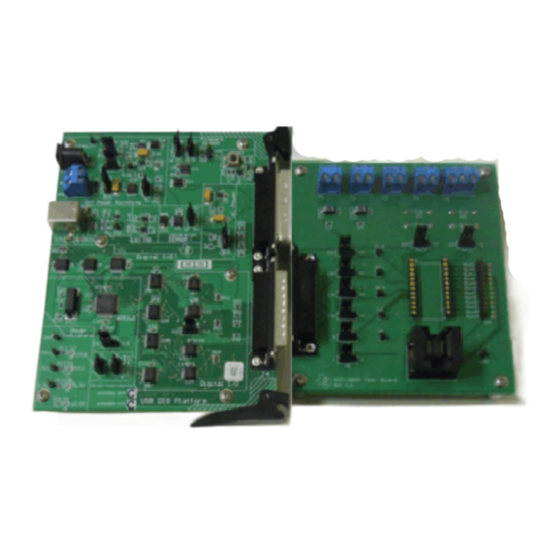
All manuals and user guides at all-guidesbox.com Overview www.ti.com BUF22821EVM-USB Kit Contents Table 1 lists the contents of the BUF22821EVM-USB kit. Figure 1 shows all of the included hardware. Contact the Texas Instruments Product Information Center nearest you if any component is missing. It is... -
Page 4: Buf22821Evm-Usb Hardware Setup
The following documents provide information regarding Texas Instruments' integrated circuits used in the assembly of the BUF22821EVM-USB. This user's guide is available from the TI web site under literature number SBOU116. Any letter appended to the literature number corresponds to the document revision that is current at the time of the writing of this document. -
Page 5: Buf22821Evm-Usb Board Block Diagram
Figure 3. BUF22821EVM-USB Board Block Diagram Signal Definitions of J1 (25-Pin Male DSUB) Table 3 shows the various signals connected to J1 on the BUF22821 test board. Table 3. J1 Signal Definition for BUF22821EVM-USB Pin No on U1 Signal BUF22821 Pin... -
Page 6: Buf22821Evm-Usb Hardware
Theory of Operation for USB_DIG_Platform Figure 4 shows the block diagram for the USB_DIG_Platform. This platform is a general-purpose data acquisition system that is used on several different Texas Instruments evaluation modules. The details of its operation are included in a separate document, SBOU058 (available for download at www.ti.com). -
Page 7: Typical Hardware Connections For The Buf22821Evm-Usb
Typical Hardware Connections Setting up the BUF22821EVM-USB hardware involves connecting the BUF22821 test board and the USB_DIG_Platform together via a 25-pin DSUB connector and then applying power. The external connections may be connected to the real-world system that the BUF22821 is to be incorporated into. -
Page 8: Connecting External Power To The Buf22821Evm-Usb
This source is not included with the kit, and its voltage may differ depending on your testing needs. The source will be used to provide dc supply voltage to the BUF22821 test board. Figure 6. Connecting External Power to the BUF22821EVM-USB BUF22821EVM-USB Evaluation Board and Software Tutorial SBOU117A –... -
Page 9: Connecting The Usb Cable To The Usb_Dig_Platform
Windows then confirms installation of the drivers with the message shown in Figure Figure 8. Confirmation of USB_DIG_Platform Driver Installation SBOU117A – September 2011 – Revised May 2016 BUF22821EVM-USB Evaluation Board and Software Tutorial Submit Documentation Feedback Copyright © 2011–2016, Texas Instruments Incorporated... -
Page 10: Default Jumper Locations For Buf22821Evm-Usb
BUF22821EVM-USB Default Jumper Settings Figure 9 shows the default jumpers configuration for the BUF22821EVM-USB. In general, the jumper settings of the USB_DIG_Platform do not need to be changed. You may want to change some of the jumpers on the BUF22821 Test Board to match your specific configuration. For instance, you may wish to set a specific I C address. - Page 11 T4 as well as resistors R3 and R4. The default position leaves the STATIN_L connection open. SBOU117A – September 2011 – Revised May 2016 BUF22821EVM-USB Evaluation Board and Software Tutorial Submit Documentation Feedback Copyright © 2011–2016, Texas Instruments Incorporated...
-
Page 12: Buf22821Evm-Usb Features
When JMP1 is set in the EXT position, an external supply connected to terminal T2 can be used to provide the digital supply voltage for the BUF22821. BUF22821EVM-USB Evaluation Board and Software Tutorial SBOU117A – September 2011 – Revised May 2016 Submit Documentation Feedback Copyright ©... -
Page 13: Bksel Switch
A0 address can be set to either a logic '1' or a logic '0' to allow for two unique I C addresses. See Section 5.0.1 on how to configure the BUF22821EVM-USB software to match the JMP5 hardware setting. SBOU117A – September 2011 – Revised May 2016 BUF22821EVM-USB Evaluation Board and Software Tutorial Submit Documentation Feedback Copyright ©... - Page 14 SUP_L BUF22821 Device Placement The BUF22821EVM-USB provides two separate locations on the board where the BUF22821 test device can be installed. Location U1 allows for a BUF22821 device that is soldered down on a DIP adaptor board to be installed on the BUF22821 Test Board.
-
Page 15: Buf22821Evm-Usb Software Setup
(OS) with United States and European regional settings. The software should also function on other Windows OS platforms. BUF22821 Software Installation The BUF22821EVM-USB software is included on the CD that is shipped with the EVM kit. It is also available through the BUF22821EVM-USB product folder on the TI web site. -
Page 16: Buf22821Evm-Usb Software License Agreements
Figure 13. BUF22821EVM-USB Software Installation Progress Software Description and Set-Up The BUF22821EVM-USB software allows the user to read and write to all registers in the BUF22821 gamma correction buffer. Furthermore, it allows programming of the OTP register on the BUF22821. The software also permits the user to select either I C address. -
Page 17: Buf22821Evm-Usb Software Interface
This section discusses how to use the BUF22821EVM-USB software. Starting the BUF22821EVM-USB Software The BUF22821EVM-USB software can be operated through the Start menu in Windows. From the Start menu, select All Programs, and then select the BUF22821EVM-USB program to start the software. -
Page 18: Communication Error With Usb_Dig_Platform
Figure 17 shows how the hardware and software must both be set to enable communication between the BUF22821EVM-USB and the software. Without jumper JMP5 and the software address button configured correctly, the software cannot communicate with the BUF22821 device. Figure 17. JMP5 Setting for Logic ‘0’... -
Page 19: Jmp5 Setting For Logic '1
6 to 0.996 V. The calculation is performed according to Equation V x Code_in_decimal DAC_CHANNEL 1024 SBOU117A – September 2011 – Revised May 2016 BUF22821EVM-USB Evaluation Board and Software Tutorial Submit Documentation Feedback Copyright © 2011–2016, Texas Instruments Incorporated... -
Page 20: Auto Write Feature Enabled
1024 Read DAC Button By pressing the Read DAC button in the BUF22821EVM-USB software, all of the BUF22821 DAC registers are read to obtain the respective current register contents. Once the read procedure is complete, all of the corresponding text boxes are updated to show the current values present in the DAC registers. -
Page 21: Save File Prompt
Reset Button Pressing the Reset button in the BUF22821EVM-USB software performs two functions. First, a General- Call Reset for the BUF22821 is performed. The status of the DAC registers after this General-Call Reset default to 1000000000, or mid-supply. The second function performed after the Reset button is pressed is that a Read DAC call is made to update the corresponding channel text boxes to the current value for each channel. -
Page 22: Saved Data Format
Figure 22. Saved Data Format Load From File Button The BUF22821EVM-USB software is also able to load data saved from previous evaluations. A saved register configuration can be loaded into the BUF22821 using the Load From File button, shown in Figure 23. - Page 23 In Figure 24, two configuration files are selected. SBOU117A – September 2011 – Revised May 2016 BUF22821EVM-USB Evaluation Board and Software Tutorial Submit Documentation Feedback Copyright © 2011–2016, Texas Instruments Incorporated...
- Page 24 25. Simply drag the slider to adjust the desired channel output. The DAC code and corresponding output value of each channel changes automatically. This action is similar to the slider present on the main BUF22821EVM-USB software window that changes based on the channel that is highlighted.
- Page 25 The values are stored in the memory bank that is selected via the BKSEL switch (see Section 4.1). Figure 26. Program OTP All Channels SBOU117A – September 2011 – Revised May 2016 BUF22821EVM-USB Evaluation Board and Software Tutorial Submit Documentation Feedback Copyright © 2011–2016, Texas Instruments Incorporated...
-
Page 26: Buf22821Evm-Usb Documentation
BUF22821EVM-USB Documentation This section contains the complete bill of materials and PCB layout for the BUF22821EVM-USB. NOTE: These board layouts are not to scale. These image are intended to show how the board is laid out; they are not intended to be used for manufacturing BUF22821EVM-USB PCBs. - Page 27 PCB Layout Figure 28 shows the PCB layout of the BUF22821EVM-USB. Figure 28. BUF22821EVM-USB PCB Top Layer (Component Layout) SBOU117A – September 2011 – Revised May 2016 BUF22821EVM-USB Evaluation Board and Software Tutorial Submit Documentation Feedback Copyright © 2011–2016, Texas Instruments Incorporated...
- Page 28 NOTE: Page numbers for previous revisions may differ from page numbers in the current version. Changes from Original (September 2011) to A Revision ....................Page ..............• Added new part to the BUF22821EVM-USB Kit Contents table....................• Changed 'Hardware Included' image...... •...
- Page 29 All manuals and user guides at all-guidesbox.com STANDARD TERMS AND CONDITIONS FOR EVALUATION MODULES Delivery: TI delivers TI evaluation boards, kits, or modules, including any accompanying demonstration software, components, or documentation (collectively, an “EVM” or “EVMs”) to the User (“User”) in accordance with the terms and conditions set forth herein. Acceptance of the EVM is expressly subject to the following terms and conditions.
- Page 30 All manuals and user guides at all-guidesbox.com FCC Interference Statement for Class B EVM devices NOTE: This equipment has been tested and found to comply with the limits for a Class B digital device, pursuant to part 15 of the FCC Rules. These limits are designed to provide reasonable protection against harmful interference in a residential installation.
- Page 31 All manuals and user guides at all-guidesbox.com 【無線電波を送信する製品の開発キットをお使いになる際の注意事項】 開発キットの中には技術基準適合証明を受けて いないものがあります。 技術適合証明を受けていないもののご使用に際しては、電波法遵守のため、以下のいずれかの 措置を取っていただく必要がありますのでご注意ください。 1. 電波法施行規則第6条第1項第1号に基づく平成18年3月28日総務省告示第173号で定められた電波暗室等の試験設備でご使用 いただく。 2. 実験局の免許を取得後ご使用いただく。 3. 技術基準適合証明を取得後ご使用いただく。 なお、本製品は、上記の「ご使用にあたっての注意」を譲渡先、移転先に通知しない限り、譲渡、移転できないものとします。 上記を遵守頂けない場合は、電波法の罰則が適用される可能性があることをご留意ください。 日本テキサス・イ ンスツルメンツ株式会社 東京都新宿区西新宿6丁目24番1号 西新宿三井ビル 3.3.3 Notice for EVMs for Power Line Communication: Please see http://www.tij.co.jp/lsds/ti_ja/general/eStore/notice_02.page 電力線搬送波通信についての開発キットをお使いになる際の注意事項については、次のところをご覧くださ い。http://www.tij.co.jp/lsds/ti_ja/general/eStore/notice_02.page SPACER EVM Use Restrictions and Warnings: 4.1 EVMS ARE NOT FOR USE IN FUNCTIONAL SAFETY AND/OR SAFETY CRITICAL EVALUATIONS, INCLUDING BUT NOT LIMITED TO EVALUATIONS OF LIFE SUPPORT APPLICATIONS.
- Page 32 Notwithstanding the foregoing, any judgment may be enforced in any United States or foreign court, and TI may seek injunctive relief in any United States or foreign court. Mailing Address: Texas Instruments, Post Office Box 655303, Dallas, Texas 75265 Copyright © 2015, Texas Instruments Incorporated...
- Page 33 IMPORTANT NOTICE Texas Instruments Incorporated and its subsidiaries (TI) reserve the right to make corrections, enhancements, improvements and other changes to its semiconductor products and services per JESD46, latest issue, and to discontinue any product or service per JESD48, latest issue.
Need help?
Do you have a question about the BUF22821EVM-USB and is the answer not in the manual?
Questions and answers